Note: Descriptions are shown in the official language in which they were submitted.
1 05 25
WO 2011/067720 1 PCT/IB2010/055520
SYSTEM FOR RECEIVING A USER
Background of the invention
The invention relates to a system for receiving a user, that
is in particular usable for being placed above, or integrated
into mattresses, armchairs or sofas for furnishings or for
motor vehicles, cushions, padded seats or backs, rucksacks,
sporting equipment, pushchairs for children, seats for
children (for example car seats or high chairs), motor-cycle
seats, or to be integrated inside a shoe. In particular, the
system in object is used to receive in a contact relationship
a part of the body of an individual, such as, for example,
the back or the sole, keeping the skin dry and removing
therefrom the sweat and the humidity.
The prior art comprises breathable fabrics which, in use, in
contact with the skin of a user, are able to maintain the
skin dry.
For example, from international patent application WO
2006/013317 a breathable fabric for clothing is known
comprising a layer of textile fibres that are permeable to
water vapour and impermeable to liquids, in which absorbing
means is positioned on at least one part of a side of the
layer of fibres.
International patent application WO 2007/034204 shows a
fabric with a side formed by hydrophobic fibres, for example,
made of polyester or polypropylene, and the opposite side
formed by a mixture of hydrophobic fibres and hydrophilic
fibres, for example in cellulose fibres such as cotton or
viscous rayon.
United States patent US 5,735,145 shows a fabric comprising a
first hydrophobic layer and a second hydrophilic layer that
are fixed together and maintained spaced apart from one
another by a series of yarns.
There are further known, for example from patent documents FR
2 700 252, CN 2912384, US 2008/0121674, WO 99/10198 and CN
2293481, mattresses, cushions or seats provided with channels
that laterally convey the sweat and the humidity sucked by an
1 05 25
WO 2011/067720 2 PCT/IB2010/055520
external layer in contact with the skin of a user.
The prior art also comprises various materials and/or
multilayered structures that are associable with clothing or
objects with which the skin of a user comes into contact.
These multilayered elements comprise a plurality of layers
made of fabric, polymers or polymer foams. The layers can be
permeable or impermeable to humidity and sweat. In particular
it is known making at least one permeable layer, at least one
impermeable layer and at least one layer (in general,
polymeric) that absorbs and collects the humidity and/or the
sweat, which are then conveyed outwards, where they are
expelled, for example by evaporation. These multilayered
elements have the object of drying, and thus making more
comfortable, the surface in direct contact with the skin of
the user owing to the elimination and removal of humidity
and/or sweat generated by the skin.
These multilayered elements are shown, for example, by the
United Kingdom patent publication GB 2 439 532, which
discloses a sheet material for absorbing water, comprising a
first layer of microbrushed polyester and a second layer of a
fabric that absorbs water (felt). The sheet may further
comprise a third permeable layer, for example of polyester
and cotton.
United States patent US 4,775,575 shows a layered fabric in
which the humidity of the body is absorbed by a lower layer
and is then transferred through an intermediate layer having
fibres that are able to absorb humidity through capillary
action, to an upper layer, having both humidity-absorbing
fibres and humidity-repellent fibres, where it evaporates.
United States patent US 4,695,496 shows a multilayered
protection coating for the skin that comprises four layers: a
first layer in contact with the skin is made of a plurality
of elongated hydrophobic fibres (for example polyester
fibres) that remove humidity and sweat from the body, a
membrane layer of perforated hydrophobic material (for
example GORE-TEX ), a layer of porous foam that stores the
drops of water that condense here, and an external covering
1 05 25
WO 2011/067720 3 PCT/IB2010/055520
layer in vinyl.
International patent application WO 2008/118070 discloses a
wetsuit comprising an external impermeable layer (for example
made of polyurethane) and an internal insulating layer. A
three-dimensional polyester fabric that is flexible and can
be traversed by the air in two directions is removably
attached to the inside of the external layer.
The publication of European patent EP 1 967 626 discloses a
sheet for absorbing sweat comprising two opposite surface
layers made of a mixture of hydrophobic and hydrophilic
fibres made of synthetic thermoplastic resin, and an internal
layer of hydrophilic fibres interposed between the two
surface layers.
International patent application WO 01/23125 discloses a
laminar structure that is impermeable to liquid but permeable
to wet vapour comprising an external layer, an opening
through which air passes, and an insulating system that
comprises a first layer, an insulating layer and a steam-
control layer.
In international patent application WO 2006/076722 a
composite, breathable and hydrorepellent sheet, comprises a
thermoplastic film, that is not porous and permeable to wet
vapour, coated on opposite sides with an absorbent layer and
a repellent layer.
Multilayered fabrics are also known for example from patent
documents WO 2007/107264, EP 1 266 584, US 4,530,873, JP
8302506 and GB 2 138 745, in particular multilayered fabrics
for garments or shoes, comprising a plurality of layers, in
materials that are different from one another, arranged for
promoting the flow of sweat and humidity from the skin to the
external layers of the fabric. In this manner, the most
internal layer of the fabric, i.e. the surface in direct
contact with the skin, is kept dry. The fabrics disclosed in
these documents comprise in particular at least one permeable
layer and/or one porous layer, that respectively enable the
liquid to flow through and absorb and collect the humidity
and/or the sweat that are then conveyed outside, where, for
1 05 25
WO 2011/067720 4 PCT/IB2010/055520
example, they are expelled by evaporation.
European patent publication EP 0 639 361 shows a composite
material for making elements for an orthopaedic support in
which a user is in contact with a fabric of hydrophobic
fibres joined to an intermediate perforated layer of foam
rubber that is in turn joined to an external section
consisting of a more internal hydrophilic layer and of a more
external hydrophobic layer. The humidity emitted by the skin
of the user passes through the fabric made of hydrophobic
fibres and the holes of the intermediate layer and is then
distributed by the first hydrophilic layer, increasing
evaporation from the second hydrophobic layer.
It is further known to make products that are intended to
come into contact with the skin of a user, by laminar
structures comprising at least one layer provided with holes
or made of porous material (for example foam or felt).
European patent application EP 0 792 594 discloses for
example a shoe with permeability to vapour in which a felt
arranged for evacuating the sweat/humidity produced by the
foot is inserted into a space obtained between the external
sole and the plantar zone.
United States patent publication US 2005/0142334 shows an
orthopaedic apparatus having a laminar structure with a
coating that encloses a material provided with large number
of channels starting from open cells, by means of which
channels the sweat can migrate from the skin outwards.
Japanese patent application JP 9135716 discloses a fabric
comprising a layer of fabric made of non-circular fibres and
impregnated with antimicrobial agents, and a layer of foam
material, for example of synthetic resin. Patent documents CN
201169219, EP 1 192 886, EP 1 454 560, GB 2 248 774, JP
2006122417, WO 94/01609 and CN 201224208 disclose a fabric
that is similar to that of JP 9135716 and is used to make
portions of seats for cars, perambulators for children,
cushions and mattresses.
From United States patent US 5,488,746 a mattress cover is
also known in which two external layers joined by a zip
1 05 25
WO 2011/067720 5 PCT/IB2010/055520
closure enclose an internal foam core to be able to wash
separately the core and the cover. Another mattress cover
provided with a zip closure is shown from Chinese patent CN
201238857.
Summary of the invention
One object of the invention is to provide a system for
receiving a user with the possibility of maintaining the skin
of the user dry by removing the sweat and humidity.
One advantage is to make a constructionally simple and cheap
system.
Another advantage is to make a system the use of which is
significantly simple and practical.
Still another advantage is to provide a system that is able
to eliminate effectively the sweat and humidity from the skin
of a user, ensuring a significant degree of comfort to the
user. This advantage can be obtained with particular efficacy
by virtue of an effect of alternating pumping air inwards the
system and pumping humidity outwards the system.
A further advantage is to make a versatile system available
that can be easily used in combination with various products
that are already known, such as, for example, mattresses,
armchairs or sofas for furnishings or for motor vehicles,
cushions, padded seats or backs, rucksacks, sporting
equipment, pushchairs for children, seats for children (for
example seats for cars or high chairs), seats for motor
cycles, shoes. The system can be advantageously applied to
these products by simple resting, or by removable connecting
means of known type (laces, Velcro, buttons, etc), or can be
integrated with the products.
Such objects and advantages and still others are all achieved
by a system according to any one of the claims set out below.
Short descriptions of the drawings
The invention can be better understood and implemented with
reference to the attached drawings that illustrate some non-
limiting embodiments.
Figure 1 is a schematic section view of a first embodiment of
the system in object.
1 05 25
WO 2011/067720 6 PCT/IB2010/055520
Figure lb is a schematic section view of a mattress into
which the system of figure 1 is integrated.
Figure 2 is a partially sectioned schematic side view of a
seat for motor vehicles into which the system in object is
integrated.
Figure 3 is a schematic perspective view of the seat in
figure 2.
Figure 4 is a schematic perspective view of the back of the
seat according to the line IV-IV in figure 2.
Figure 5 is a schematic side view of a shoe into which the
system in object is integrated.
Figure 6 is a partial, schematic and enlarged section view,
according to plane VI-VI in figure 5.
Figure 7 is a schematic perspective view of a seat for
children for motor vehicles in which the system in object is
integrated.
Figure 8 is a perspective view of a pushchair for children in
the seat of which the system in object is integrated.
Detailed description
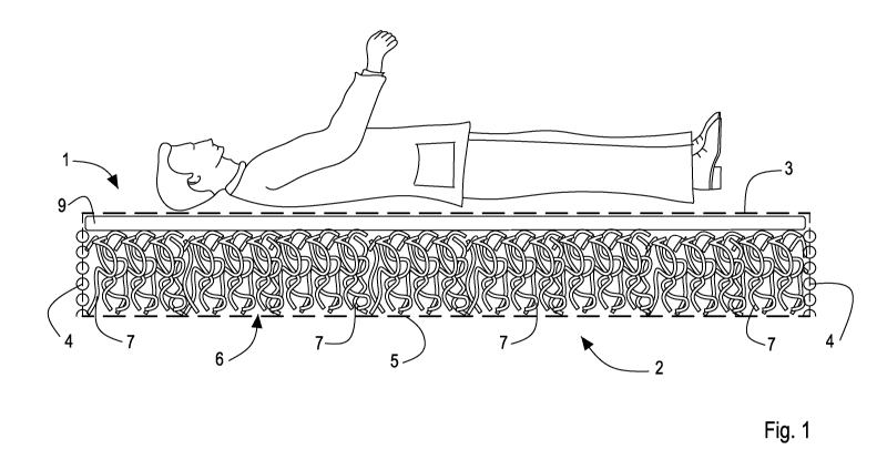
With reference to figure 1, with 1 an embodiment of the
system in object has been indicated on the whole.
In the specific case of figure 1 the system is in the shape
of a cushion or mattress cover that can be placed, for
example rested, in a free or bound manner, with known
attaching means, on the upper side of a mattress (known and
not illustrated).
Figure lb shows a mattress 50 into which the system of figure
1 is integrated, a system that will be disclosed in detail
below. It should be noted that the system is located inside
the mattress 50, in particular at the zone where a user can
lie down.
The system 1 comprises an external covering or casing 2. The
casing 2 has a first portion 3 intended for the contact with
an individual. The first portion 3 is made of a material (of
known type) comprising hydrophilic fibres and hydrophobic
fibres configured for conveying liquids or wet vapour from
outside to inside the casing. In particular, the first
1 05 25
WO 2011/067720 7 PCT/IB2010/055520
portion 3 is structured in such a manner as to convey sweat
and humidity from outside to inside the casing 2.
The first portion 3 can be made of a fabric, of known use,
for example, in the clothing sector, that is able to exert an
effect called "push-pull". This type of fabric is already
used, as said, in garments that, in contact with the skin of
a user, have the ability to absorb the sweat and/or the
humidity and to convey the sweat and/or the humidity
outwards, where they can be eliminated, for example through
evaporation. In the case in object, the "push-pull" fabric
that may form the first portion 3 of the casing 2 is
configured in such a manner as to absorb the sweat and/or the
humidity and to transfer the sweat and/or the humidity to the
inner side of the casing 2, i.e. inside the system 1.
In the present patent application, the expression "push-pull"
means any fabric or material that is able to exert the so-
called "push-pull" effect, which is well-known to those
skilled in the art, and not just a "push-pull" fabric like
those of known type.
The casing 2 has at least a second portion 5 opposite the
first portion and at least a third peripheral portion 4 that
joins the first portion 3 to the second portion 5. The second
portion 5 and/or the third portion 4 are made of a material
that is permeable to air and humidity, such as, for example,
GORE-TEX or anyway a porous material that enables wet vapour
to exit outwards and air to enter inwards. The casing 2, in
particular the portions 4, 5 thereof, can be made of a
breathable perforated fabric provided with a plurality of
holes or microholes (which are not shown).
The casing 2 encloses an internal padding 6 that is wound by
the casing 2. The padding 6 is interposed between the first
portion 3 and the second portion 5. The casing 2 can be
detached from the padding 6, so that the casing 2 can be
washed separately from the padding 6. In particular, the
casing 2 can be provided with a rapid closing and opening
device, of known type and not illustrated, that enables the
padding 6 to be inserted into and extracted from the casing
1 05 25
WO 2011/067720 8 PCT/IB2010/055520
2. The rapid closing and opening device of the casing may
comprise, for example, a normal zip-fastener or other device
to removably connect a pair of longitudinal flaps of the
casing 2 that extend, optionally, at least in part, along the
third casing portion 4. It is anyway possible to provide for
the system 1 having the casing 2 integrated to the padding 6.
The casing 2 may further comprise a permeable layer 9 of
polyurethane foam interposed between the first portion 3 and
the padding 6. This layer can be further provided with a
plurality of holes (not shown in figures 1 and lb) that are
substantially vertical so as to increase the absorption of
sweat and/or humidity from the first portion 3 to the padding
6, and thus the comfort of the user.
The internal padding 6 has a porous structure to permit
ventilation inside the casing 2. The padding has a
compressible variable-volume structure with spring-back. In
the embodiment in figure 1, which is illustrated by way of
example, the third casing portion 4 is made in such a manner
as to enable air to enter and humidity to exit through the
effect of the variation of the volume of the structure of the
padding ("in-out" pumping effect). In other words, the casing
2 (and in particular the portions 3, 4, 5 thereof) defines a
pumping chamber or cavity with a variable volume in which the
padding 6 is received.
The padding 6 may comprise, for example, an arrangement of
elements 7 with an elongated shape, which are visible in
Figure 1. These elements 7 can be intertwisted together, for
example in a disorderly manner. The padding 6 can be made of
plastics (such as, for example, polyethylene), or of another
material. The plastics of the padding can have a resistance
to crushing that is greater than about 1 kg/m2.
The third portion 4 can have an annular edge connected to the
first portion 3. The third portion 4 can also have a further
annular edge connected to the second portion 5. The
connections between the various casing portions may be of
irremovable type, like, for example, normal seams.
In use, the first portion, which is frontal i.e. in contact
1 05 25
WO 2011/067720 9 PCT/IB2010/055520
with the user, absorbs sweat and conveys the sweat to the
inner side of the casing, exploiting the "push-pull" effect
due to the combination of hydrophilic and hydrophobic fibres.
The material of the padding 6, having a structure that is
porous or anyway permeable to air, enables ventilation inside
the casing. The third casing portion 4, which is arranged on
the peripheral zone of the system 1 and is not normally in
contact with the user, enables the exit from inside outwards
the casing of the sweat and/or humidity previously absorbed
and transferred from the outside inwards through the first
portion 3.
The exit of sweat and/or humidity can be promoted by a
pumping effect ("in-out pumping effect") due to crushing of
the padding by the user, who naturally moves on the mattress
onto which the system 1 has been placed.
The movements of the user entail an alternating effect of
both pumping of wetter air from inside the casing outwards
the casing (through the portions 4 and 5) and sucking of
dryer air from outside the casing inwards the casing. This
permits an air exchange and better ventilation and removal of
sweat and/or humidity from the system, with an increase in
the sensation of comfort of the user.
In other embodiments of the system according to the
invention, which are not shown, the pumping effect ("in-out
pumping effect"), i.e. the variation in volume of the padding
6, can be obtained, for example, by mechanical devices driven
by means of any pneumatic, or electric or hydraulic driving
means that enables the padding 6 to be compressed and
expanded alternately in order to obtain the desired effect
disclosed above.
The third casing portion 4 can further act as a barrier to
liquids, in particular water, both outwards and inwards the
casing. Alternatively, the third portion 4 can also be
permeable to liquids.
Also the second portion 5 can contribute to the entry of air
inside the casing 2. Further, this second portion 5, which
can be made of a material that is impermeable to liquids and,
1 05 25
WO 2011/067720 10 PCT/IB2010/055520
optionally, also to vapour, can prevent the exit of humidity,
in particular retaining liquids to preventing wetting on the
outside.
In figures 2 and 3 there is illustrated a seat 10 for a motor
vehicle into which a system 11 according to the invention is
integrated.
The seat 10 comprises a seat 14' and a back 15', both
comprising the system 11. In one embodiment that is not shown
the system 11 can be integrated only into the seat or only
into the back.
Figure 4 illustrates a partial section of the seat into which
the system 11 has been inserted, having a casing 12
comprising a first external portion 13 intended for contact
with an individual, a second portion 15 opposite the first
portion 13 and a third peripheral portion 14 that joins the
first portion 13 to the second portion 15. The first portion
13 includes, for example, a "push-pull" fabric provided with
hydrophilic fibres and hydrophobic fibres, such as to convey
sweat and/or humidity from outside inwards the casing 12.
The second portion 15 and the third portion 14 comprise
respective portions of a filling body 18 of the seat made
typically of polyurethane foam, and obtained by injection
moulding. The casing 12 substantially forms a chamber or
cavity containing the padding 6 that comprises, similarly to
the embodiment of the system 1 in figure 1, an arrangement of
elements 7 of elongated shape that can be intertwisted
together, for example in a disorderly manner. The padding 6
can be made of plastics (such as, for example, polyethylene),
or of another material.
The casing 12 further comprises a fourth portion 19
interposed between the first portion 13 and the padding 6,
which is also made of polyurethane foam like the second
portion 15 and the third portion 14. The fourth portion 19,
which is optional, ensures the user greater comfort if the
first portion 13 is too thin or stiff. It should be noted
that the fourth portion 19 can be fixed to the first portion
13, as occurs in seats of known type.
1 05 25
WO 2011/067720 11 PCT/IB2010/055520
The third portion 14 comprises a plurality of holes 17 that
connect the inside of the casing 12, i.e. the chamber in
which the padding 6 is housed, with the outside of the seat
such as to enable both the air to enter into said chamber
5 to obtain the desired ventilation and the sweat and/or
humidity that have been previously absorbed and transferred
from outside to inside through the first portion 13 to exit
from inside outwards the casing 12 through the second portion
15. The holes 17 can be advantageously made in suitable
10 positions of the filling body 18 of the seat 14', so as to
face zones of the supporting frame of the seat that are
devoid of metallic material. In other words, the holes 17
face respective holes obtained in the metallic supporting
frame of the seat.
The fourth portion 19 comprises a further plurality of
through holes 17', that are suitable for further promoting
the absorption of sweat and/or humidity from the first
portion 13 to the padding 6 and in general to improve
ventilation of the seat through the passage of air from the
padding 6 to the first portion 13.
In an embodiment that is not shown, the fourth portion 19 is
devoid of the further plurality of holes, absorption of sweat
and/or humidity being obtained owing to the properties of the
material with which the fourth portion 19 is made, i.e. the
polyurethane foam.
It should be noted that in this embodiment the casing 12 of
the system 11 is made by using already existing portions of
the seat, in particular an external cover thereof that acts
as a first portion 13, and a filling body 18 thereof that
forms the second portion 15, the third portion 14 and the
fourth portion 19.
In use, the system 11 operates substantially in the same
manner as disclosed previously with reference to figure 1. In
particular, the first portion 13 of the casing 12, which is
frontal i.e. in contact with the user, absorbs the sweat
and/or the humidity and conveys the sweat and/or the humidity
- through the further plurality of holes 17' - inside the
1 05 25
WO 2011/067720 12 PCT/IB2010/055520
padding 6, the material of which (for example polyethylene)
enables the inside of the seat 10 to be ventilated. In
particular, the sweat and/or the humidity are then conveyed
outside the seat 10 through the plurality of holes 17
provided on the second portion 15 of the casing 12. The exit
of sweat and/or humidity can be promoted by a pumping effect
("in-out pumping effect") owing to the crushing of the
padding 6 by the user, who moves, naturally, on the seat 10.
The movements of the user entail an alternating effect of
both pumping of wetter air from inside the casing 12 outwards
the casing 12 and sucking of drier air from outside the
casing inwards the casing, these pumping and sucking actions
both occurring preferably through the holes 17 made in the
second portion 15. This enables an exchange of air and better
ventilation and removal of sweat and/or humidity from the
system 11, with an increase in the sensation of comfort of
the user seated on the seat 10. As will be clear to those
skilled in the art, integrating the system 11 into the seat
10 is simple and does not entail additional manufacturing
costs. In fact, it is sufficient to modify suitably the mould
for forming the filling body 18 of the seat 10, so as to
obtain in the filling body 18 a housing or chamber that is
able to receive the padding 6.
In figure 5 there is illustrated a shoe 20 of known type into
which a system 21 according to the invention is integrated.
Figure 6 illustrates a partial section of the shoe into which
the system 21 has been inserted, comprising a casing 22 that
includes a first portion 23 intended for contact with the
foot of a user, a second portion 25 opposite the first
portion 23 and a third portion 24 arranged laterally, not
intended for contact with the ground, to join along the
perimeter the first portion 23 with the second portion 25
such as to define, in cooperation with the first portion 23
and the second portion 25, a chamber for housing the padding
6. The first portion 23 includes, for example, an insole made
of "push-pull" breathable material or fabric, i.e. which is
provided with hydrophilic fibres and hydrophobic fibres, such
1 05 25
WO 2011/067720 13 PCT/IB2010/055520
as to convey sweat and/or humidity from inside the shoe 20 to
inside the casing 22, in particular in the padding 6.
The second portion 25 forms at least one part of the sole 32
of the shoe 20 intended for contact with the ground, and the
third portion 24 bounds inferiorly the upper 31 of the shoe
20. The padding 6 comprises, similarly to the embodiments of
the system disclosed above and illustrated in figures 1, lb
and 2-4, an arrangement of elements 7 of elongated shape that
can be intertwisted together, for example in disorderly
manner, made of plastics (such as, for example,
polyethylene), or of another material.
The shoe 20 can be provided with a further portion 28 of
padding made of a foam material superimposed on the first
portion 23 and forming at least a part of a further insole 28
intended in use for contact with the sole of a user. The
insole 23 and the further insole 28 are perforated to allow
better breathability and thus the passage of sweat and/or
humidity from inside the shoe 20 to inside the casing 22.
On the third portion 24 of the casing 22 a plurality of holes
27 are made that place the aforesaid chamber in communication
with the external environment. The holes 27 are, for example,
cylindrical, and can be arranged according to an appropriate
inclination.
In use, the system 21 operates substantially in the same
manner disclosed previously with reference to figure 1. As is
visible in figures 5 and 6, the first layer 23 or insole (for
example made of perforated fabric) and the further insole 28
(which, for example, is also made of perforated fabric) on
both of which the sole of the user rests absorb the sweat
and/or the humidity, and convey the sweat and/or the humidity
inside the padding 6, the material of which enables the
inside of the shoe to be ventilated. Sweat and/or humidity
are then conveyed outside the shoe through the holes 27. The
exit of sweat and/or humidity can be promoted by a pumping
effect ("in-out pumping effect") due to the crushing of the
padding 6 by the foot during the natural movement thereof
whilst the user is walking. The movements of the user entail
1 05 25
WO 2011/067720 14 PCT/IB2010/055520
an alternating effect of both pumping of wetter air from
inside the shoe outwards the shoe and sucking of drier air
from outside the shoe inwards the shoe, pumping and sucking
both occurring through the holes 27. This enables an exchange
of air and better ventilation and removal of wet sweat vapour
from the system, with an increase in the sensation of comfort
of the user. It should further be noted that the padding 6,
owing to the structure thereof, further acts as a shock
absorber, so as to be make the shoe less stiff and thus even
more comfortable for the user.
In figure 7 there is illustrated a seat 10' for conveying
children in a vehicle that is made with similar elements to
those of the seat 10 in figures 2-4 and is therefore
substantially the same as the latter. Into seat 10' a system
11 is integrated (disclosed above and shown in detail in
figure 4), arranged at various zones of the seat 10', in
particular where the child rests the head, the back and the
lower limbs. It is intended that such zones are shown by way
of non-limiting example. In these zones, owing to the
presence of the padding 6 made of plastics comprising the
arrangement of elongated elements 7, the sweat and/or the
humidity generated by the skin can be disposed of and
eliminated to the inside of the seat, such as to make it more
comfortable and dryer. It should be noted that, unlike the
system 11 disclosed above, the seat 10' comprises a second
portion 15 on which the plurality of holes 17 is made that is
not made of polyurethane foam but is a stiff structural
portion of the seat itself, generally made of plastic
material and having holes in suitable positions.
In figure 8 there is illustrated a pushchair 60 for children
that is made with similar elements to those of the system 1
in figure 1 and are therefore indicated by the same
numbering: in particular the first portion 3 and the third
portion 4 are visible. The seat of the illustrated pushchair
can also be made like the seat 10 disclosed above and shown
in figures 2-4.
The system in object can be effectively placed on mattresses
1 05 25
WO 2011/067720 15 PCT/IB2010/055520
or can be integrated into seats for motor vehicles or into
shoes, as disclosed above. Further, the system can also be
placed upon, or integrated into, armchairs or sofas for
furnishings, padded seats or backs for various applications
of known type, cushions, rucksacks, sports equipment,
pushchairs for children, seats for children (for example
seats for cars or high chairs), seats for motor cycles, etc.
In all the applications of the system in object it is
possible for the casing to be of the integrated type with the
padding or to be of the removable type.