Note: Descriptions are shown in the official language in which they were submitted.
CA 02782165 2016-10-25
- 1 -
Pipeline welding method and apparatus
Background of the Invention
The present invention relates to an apparatus and method for welding pipes
together. In
particular, but not exclusively, the invention relates to welding together
clad pipe sections, or
other multilayer pipe sections, when laying pipelines underwater at sea.
When laying a pipeline at sea from a pipe-laying vessel, one end of the
pipeline
(sometimes referred to as the "pipe string") is held by the vessel and a pipe
section is welded to
the end of the pipeline. The pipeline and newly welded pipe section are then
fed out from the
vessel, so that the process can be repeated. The weld joint must be of high
quality in view of the
high tensile loads to which the pipeline is subjected during the laying
process. Quality of weld
joints is critical when the pipeline will, once installed, be in a position
where it is exposed to
regular changing motion in the sea (for example when the pipeline is in the
form of a catenary
riser). In such case, the weld joint must be able to withstand the fatigue
loads to which it will be
subjected.
Pipelines designed to convey liquid or gases that are corrosive or otherwise
able to
damage normal steel pipes are typically internally clad or otherwise lined
with CRA (corrosion
resistant alloy). Also, such CRA-lined pipelines are increasingly found to
offer an economic
solution to the exploitation of remote wells. CRA-lined pipes are made by
metallurgically
bonding, or pressing, a CRA cylinder to the inside of a carbon steel (CS)
pipe.
The process of welding together CRA-lined pipes is more complex than welding
of
normal CS pipeline. It should be noted that the production rate for a CRA
pipeline is typically a
factor of 4 or 5 times less than that of a CS pipeline of the same dimensions.
A typical CS pipe
clad with CRA materials and the weld joint formed therebetween is shown in
Figures la, lb and
2.
A known technique for welding together CRA-lined pipe sections is to use a
single
externally mounted semi-automated GMAW welding head for depositing the
critical first pass
indicated as root pass, followed by an internal inspection =to ensure the
quality of the root weld is
of a sufficiently high standard. The weld area is purged with protective
shielding gas (usually
an inert gas such as argon) to reduce the risk of oxidation of the weld
material. The internal
CA 02782165 2016-10-25
- 2 -
inspection includes an ultrasonic testing regime and a visual inspection
performed with the aid
of cameras. The visual inspection is required because the ultrasonic testing
can be prone to false
results due to residual magnetization of the CRA material.
As a result of the nature of the root-welding process, it is difficult to
ensure proper weld
penetration. The whole welding process is very sensitive to variations in many
parameters such
as joint fit-up, levels of magnetism and even small changes in gas
composition. Despite the
large degree of automation that such a welding process provides, the
acceptance of the weld still
remains very dependent on the skill of the welder. The overall cycle time to
complete the first
two root passes and perform the internal inspection is relatively extended.
Furthermore, if the
root weld fails to meet the strict acceptance criteria, it is generally the
case that root repairs are
not performed and instead the whole weld-joint is cut-out, leading to further
delays. The joint is
welded to the hot pass stage and internally inspected before being moved out
of the welding
station. When steady-state production is being achieved, a welding cycle time
of about 30
minutes at the first welding station may be achieved, but achieving a welding
cycle of that
duration can be a challenge when laying pipeline at sea. It will be
appreciated that after the root
weld is finished, the pipe is moved to subsequent stations to be filled with
the other weld passes
and/or processed/tested in other ways. The operations at the station where the
root pass is laid
down tend however to be the rate-limiting step.
The present invention seeks to mitigate the above-mentioned problems.
Alternatively or
additionally, the present invention seeks to provide an improved method of
laying a pipeline, an
improved welding method, and/or an improved pipe-welding apparatus.
Summary of the Invention
The present invention provides a method of laying a pipeline, in which pipe
sections are
welded together to form the pipeline. It will be appreciated that the pipe
sections and the pipeline
may be referred to simply as pipes. The method includes the steps of providing
a pipe section to
be welded to the end of a pipeline, arranging the pipe section adjacent to the
end of the pipeline
thereby defining a circumferential joint to be welded, performing an external
weld pass on the
root of the joint to be welded during which weld material is deposited in the
root of the joint to be
welded, thereby forming a root weld, and performing an internal weld pass on
the root weld.
CA 02782165 2016-10-25
-3 -
Advantageously, the step of performing the internal weld pass on the root weld
melts and re-
shapes the root weld. The melting of the already-formed root weld may be
performed to cause
remelting of the internal surface to a depth of more than 0.5mm and more
preferably more than
lmm. Such remelting of the root-weld can improve the chance of achieving full
fusion at the
root of the weld joint, which can otherwise be difficult to achieve reliably.
The reshaping of the
root weld from within the interior of the pipes can improve overall weld
quality and reduce the
chance of the weld being rejected as not meeting acceptability criteria.
The method includes a step of performing an external weld pass on the root of
the joint to
be welded and a step of performing an internal weld pass on the root weld. The
apparatus for
performing the external weld pass will be referred to as the external welding
apparatus and the
apparatus for performing the internal weld pass will be referred to as the
internal welding
apparatus.
The step of performing the external weld pass to form the root weld may be
performed in
such a way as to cause melting or deformation of the interior pipe surface in
the region of the root
weld. Penetration of the root weld, formed by the external weld pass, through
the interior surface
of the pipe can leave an irregular and undesirable weld. Reshaping of such a
weld from within
the pipes can be of significant benefit as explained in further detail below.
The reshaping of the root weld from inside the pipes may be performed in such
a way as
to reduce the risk of the weld being rejected as a result of the pipes being
misaligned. If the pipe
section is not exactly aligned with the adjacent end of the pipeline, there
may be a "hi-lo" (a step
from one pipe-section to the adjacent pipe section) at certain circumferential
positions around the
pipe circumference. If the hi-lo is too great, the weld will be rejected. In
embodiments of the
present invention hi-lo steps of the order of 1.5mm can be accommodated,
resulting in less time
being required in the fitting together (aligning) of pipes. Acceptable
tolerances in the shape and
dimensions of sections of pipe also become less critical, allowing potential
cost savings.
The use of an internal welding step, following an external welding step on the
same weld,
may be performed in such a way to allow for certain defects in a root weld to
be repaired in a
manner not previously envisaged. For example, in prior art welding methods of
laying pipeline at
sea, there is no repair option in the event that the root bead is rejected: in
such an event, the
whole weld is typically cut-out.
CA 02782165 2016-10-25
- 4 -
Remelting the root weld can improve the fullness of the fusion between the
weld and
pipes. Narrow bevels have been known to lead to lack of side wall fusion,
especially near the
root of the weld. However, the method of the invention can improve fullness of
weld fusion,
thereby allowing a narrow bevel to be more readily used. A narrow bevel may
have a maximum
width of less than lOmm, and preferably less than 7mm. The ratio of the
thickness of the pipes
(which may for example be between lOmm and 30mm) and the maximum width of the
bevel is
preferably between 10:1 and 3:1, and more preferably between 6:1 and 20:7.
The internal weld pass on the root weld is preferably performed by means of
arc-welding.
The internal weld pass may be performed by using a non-consumable electrode.
The internal
weld pass on the root weld may be performed without adding weld filler
material. The internal
weld pass on the root weld may for example be performed by means of an
autogenous weld
process. The internal weld may be performed by means of a plasma welding
apparatus. The
internal weld may be performed by means of a laser welding apparatus. The
internal weld may
be performed by means of a welding apparatus that utilises a tungsten
electrode. For example,
the apparatus for forming the internal weld may include a GTAW (gas tungsten
arc welding)
welding torch, for example a TIG (tungsten inert gas) welding torch. The
internal weld pass on
the root weld may be performed with the assistance of one or more cameras used
to guide the
internal welding. The one or more cameras may for example be used to produce a
live image on
a video display device. The internal welding apparatus may be partly manually
controlled. For
example, a welding operator may use an input device, for example a joystick,
that allows the
internal welding apparatus to be steered, or otherwise controlled. The
internal welding apparatus
may be at least partly automatically controlled. The internal welding
apparatus may for example
weld at a substantially constant speed along the joint to be welded. The
internal welding
apparatus may include an automatic welding voltage control (AVC) unit. The
internal welding
apparatus may include an internal line-up clamp, arranged to enable the pipes
to be lined up and
clamped in position ready for welding. One or more welding heads may be
mounted on the
internal line-up clamp (ILUC).
The step of performing the external weld pass on the root weld is preferably
performed by
means of arc-welding. The external welding step preferably includes adding
weld filler material
to the weld. The external welding step may be performed by using a consumable
electrode. The
external welding step may include performing a GMAW (gas metal arc welding)
process. For
CA 02782165 2016-10-25
-5 -
example, the GMAW process may be a MIG (metal inert gas) process. The external
welding
apparatus may be at least partly automatically controlled. The external
welding apparatus may
for example weld at a substantially constant speed along the weld. The
external welding
apparatus may include an automatic welding voltage control unit. The external
welding
apparatus may include one or more welding torches that are arranged to
automatically track (i.e.
follow) the centre of the path of the joint to be welded. The welding head may
be arranged to
oscillate across the width of the weld joint. The external welding apparatus
may include an
external clamp mechanism, for example a band, on which the one or more welding
heads are
mounted. The external welding apparatus may include one or more welding bugs
arranged to
travel around the pipes.
In the case were the external weld pass on the root requires an inert gas to
be used, the
internal weld pass, in which the root weld is remelted, preferably results in
a final surface with
low oxidation properties, thus reducing the need for purging the weld area
with inert gas before
the external passes. For example, an internal GTAW welding process may give a
final surface
with low oxidation and potentially enhanced corrosion properties, and may not
adversely affect
the mechanical properties of the root weld, despite being remelted.
The external weld pass on the root weld may include simultaneously using a
plurality of
separate welding heads. For example, a plurality of heads may deposit weld
material in the root
at different circumferential positions around the pipes. The first external
pass can be deposited
faster with two or more heads being used simultaneously. Consistently
achieving full penetration
with the external weld pass(es) may not necessarily be required because full
fusion may be later
achieved by means of the internal weld pass. Two of the separate welding heads
may be
positioned more than 60 degrees apart around the circumference of the pipes.
For example, just
two external welding heads could be provided opposite each other (i.e. about
180 degrees apart).
The step of performing an internal weld pass on the root weld may include
remelting the
interior surface of the pipes to a depth of more than 1 mm. The depth of
remelting of the interior
surface of the pipes may be less than 4mm. A typical depth of remelting may be
between 1.5 and
2.5mm.
The step of performing the external weld pass on the root of the joint may
produce a root
weld which on the internal surface of the pipes has a rough shape. In such a
case, the internal
weld pass advantageously remelts and reshapes the root weld so that on the
internal surface of the
CA 02782165 2016-10-25
- 6 -
pipes the root weld has a smoother shape. By smoothing the shape of the root
weld on the
interior surface of the pipes, the root weld may be less likely to corrode. A
weld having a rough
shape exposes more surface area per volume and is more likely to corrode. A
weld having a
rough shape may for example have an overhang when viewed in cross-section. A
weld having a
rough shape may for example have a cross-section, where the shape changes in
height (the
dimension along a radius of the pipe) by more than lmm over a distance (for
example, along the
longitudinal direction) of 1 mm. A weld having a smooth shape may be
substantially flat and
have no overhangs. A weld having a smooth shape may for example have no part
where the
shape changes in height by more than 0.5mm over a distance of 0.5mm. The step
of performing
the internal weld pass on the root weld is preferably performed such that the
root weld on the
internal surface of the pipes has a flatter shape than the shape of the root
weld formed
immediately after performing the step of the external weld pass on the root of
the joint.
The step of performing the external weld pass on the root of the joint may
produce a lack
of fusion of the material on the bevel; the root weld is not fully fused to
the pipes. In such a case,
the internal weld pass advantageously remelts the root weld so that it becomes
fully fused to the
pipes.
For a given root weld, the method may comprise performing only one internal
weld pass
per weld joint. The method may include performing only two internal weld
passes per weld joint.
In some embodiments, the method may include performing a plurality, for
example at least three,
of internal weld passes per weld joint. Three or fewer internal weld passes
per weld joint are
preferred. The root weld may be re-shaped during each such internal weld pass.
The internal welding step may include adding weld filler material to the weld.
The
addition of filler metal during the internal weld pass could for example
enable defects to be
repaired and also to fill in root weld concavities.
The method may include a step of performing an external cap weld pass on the
cap of the
joint to be welded. For example, the method may include depositing weld
material on the cap of
the joint to be welded, thereby forming a cap weld. In such a case, step of
performing the
internal weld pass on the root weld may be performed before the completion of
the step of
performing an external cap weld pass. The internal weld pass on the root of
the joint may be
performed at the same time as an external weld pass is performed. The method
may be performed
such that the internal weld pass is started only after external weld pass on
the root has been
CA 02782165 2016-10-25
- 7 -
completed. The root weld may have solidified by the time the internal weld
pass is conducted on
the root weld
The method may include a step in which non-destructive testing (NDT) is
performed. For
example, such NDT may be performed after performing the internal weld pass on
the root weld.
During the step of non-destructive testing (NDT), the quality of root weld may
be inspected by
means of one or more cameras inside the pipes. During the step of non-
destructive testing
(NDT), the quality of root weld may be tested by means of ultrasonic testing.
The step of non-
destructive testing (NDT) may be performed before the completion of the step
of performing an
external cap weld pass. The step of non-destructive testing (NDT) may use one
or more cameras.
In its broadest sense the present invention covers welding together two
sections of pipe
which are subsequently to be welded to other sections of pipe, or a pipeline,
when laying a
pipeline. Thus, one of the two pipe sections may be considered as defining the
end of a pipeline.
More common however is the case where the pipe section is added to a pipeline
which is
significantly longer (more than 10 times longer for example) than the pipe
section. The pipeline
may extend into water, for example, when the pipeline being laid is an
undersea pipeline. One
end of the pipeline may of course be held above water, for example held on a
pipe-laying vessel,
to allow a new pipe section to be welded to the end of the pipeline.
The method of the present invention has particular application when the
pipeline is multi-
layer pipeline, having one metallic layer which is made from a metal different
from that of an
adjacent layer. For example, the pipe section may be a CRA-lined pipeline. The
step of
performing the external weld pass on the root of the joint may include adding
weld material of a
first type to the joint. The step of performing the internal weld pass on the
root of the joint may
include adding weld material of a second type to the joint. The weld material
of the second type
may be of a composition different from the first type. For example, it could
be possible to weld a
clad pipe externally with CS filler metal, and internally with GTAW with CRA-
compatible filler
material. The weld material of the second type may be of the same composition
as that of the
weld material of the first type. For example, it could be possible to weld a
clad pipe externally
and internally with CRA-compatible filler material, such as "Inconel".
Together the steps of (i)
performing the external weld pass and (ii) performing the internal weld pass
may include adding
weld material of the same type both to carbon steel material and to CRA
material. For example,
CA 02782165 2016-10-25
- 8 -
"Inconel" material may be used in the external weld pass, in which the Inconel
material welds to
both the carbon steel and the CRA material in the pipeline.
The method of the present invention has particular application when the
pipeline is
subject to high loads, and/or fatigue loading. For example, at least a part of
the pipeline may
form at least part of a catenary riser. The method may be performed as part of
a method of laying
a pipeline at sea. The pipeline may be an underwater or subsea pipeline.
The pipes may be welded together with the axes of the pipes being
approximately
horizontal. For example, the laying method may be an S-lay method. The pipes
may be welded
together with the axes of the pipes being more vertical than horizontal. For
example, the laying
method may be a J-lay method. The orientation of the pipes need not materially
affect the extent
to which the internal weld can be remelted or reshaped.
The present invention also provides in accordance with a second aspect of the
invention, a
welding station for use in a method of laying a pipeline. The welding station
may include an
exterior welding apparatus and an interior welding apparatus. The interior
welding apparatus
and the exterior welding apparatus are preferably arranged to be able to
operate simultaneously.
The exterior welding apparatus may include a plurality of welding heads and an
external guiding
apparatus, each head having at least one welding torch, the welding heads
being arranged to
simultaneously weld the pipe sections together from outside the pipe sections
to form a weld joint
and to be guided along the joint to be welded at least partly by the exterior
guiding apparatus.
The interior welding apparatus may include an internal line-up clamp which
holds an internal
guiding apparatus and at least one welding head, the welding head being
arranged to remelt a
weld joint formed by the exterior welding apparatus and to be guided along the
joint by means of
internal guiding apparatus. The internal line-up clamp may also hold non-
destructive testing
(NDT) equipment, including for example one or more electronic cameras, for
performing NDT
on the root weld from inside the pipe sections. The internal line-up clamp may
include integrated
plasma-welding equipment for performing the interior weld. The welding station
may include an
internal line-up clamp and interior welding apparatus arranged separately from
the internal line-
up clamp. For example, the interior welding apparatus may be provided on a
carriage that is
moveable independently of the internal line-up clamp. The interior welding
apparatus may be so
arranged to define a central open region for accommodating an umbilical or
working shaft. In
such a case, an existing installation of a welding station having an internal
line-up clamp and
CA 02782165 2016-10-25
- 9 -
umbilical assembly and an external welding apparatus may be readily modified
to perform the
method of the present invention by mounting an internal welding apparatus onto
the internal line-
up clamp of the existing installation, for example onto the front of the
internal line-up clamp.
The welding heads of the exterior welding apparatus may be a consumable-
electrode
welding heads (such as GMAW welding heads). The welding head of the interior
welding
apparatus may be a non-consumable-electrode welding head. The interior welding
apparatus
may comprise GTAW welding equipment. The interior welding apparatus may
comprise plasma
welding equipment. The interior welding apparatus may comprise one or more
GTAW and/or
plasma welding heads.
The present invention also provides in accordance with a third aspect of the
invention, a
pipe-laying vessel including a plurality of welding stations arranged in
series in the pipe-laying
direction, wherein at least one of the welding stations is a welding station
according to the present
invention.
It will of course be appreciated that features described in relation to one
aspect of the
present invention may be incorporated into other aspects of the present
invention. For example,
the method of the invention may incorporate any of the features described with
reference to the
apparatus of the invention and vice versa.
Description of the Drawings
An embodiment of the present invention will now be described by way of example
only
with reference to the accompanying schematic drawings of which:
Figure la is a longitudinal cross-sectional view of two CRA-clad pipes that
have been welded
together in accordance with conventional techniques;
Figure lb is a cross-sectional view of the pipes shown in Figure la, taken
along the lines B-B
in Figure la;
Figure 2 is a longitudinal cross-section of a weld-joint between two pipes
that have been
welded together in accordance with conventional techniques;
CA 02782165 2016-10-25
=
=
- 10 -
Figures 3a to 3c are longitudinal cross-sections of the ends of bevelled CRA-
clad pipe sections
to be welded by means of a method in accordance with the embodiment of the
invention;
Figures 4a and 4b show two pipes being welded together in accordance with the
embodiment
of the invention;
Figures 5a to 5c are photographs showing sections of a first pipe joint
including sections
showing the weld during and after performance of the welding method of the
embodiment;
Figures 6a to 6c are photographs, similar to those of Figures 5a to 5c, but
showing sections of
a second pipe joint; and
Figures 7a to 7c are photographs, similar to those of Figures 5a to 5c, but
showing sections of
a third pipe joint.
Figure 8a shows an internal line up clamp (ILUC) in accordance with an
embodiment of the
invention.
Figures 8b to 8c show a schematic representation of an internal line up clamp
which is
arranged across a weld joint.
Detailed Description
The presently described embodiment of the invention concerns the butt-welding
together
of Corrosion Resistant Alloy (CRA) clad pipe sections during a method of
laying an underwater
pipeline from a floating vessel. The pipeline is laid overboard a vessel by
welding successive
sections of pipe to the end of the pipeline. When laying a pipeline, the
tension in the pipeline
being laid is significant and is typically of the order of several hundreds of
kilo-Newtons. During
laying and subsequent use of the pipeline, the pipe joints may be subject to
fatigue loading.
It is therefore of particular importance to ensure that the joints between the
sections of
pipe that make up the pipeline are of a very high quality. Failure of any
joint in the pipeline after
the joint has been lowered from the vessel into the water can be possibly
dangerous and
extremely costly.
Figure la shows two pipe sections 2 in longitudinal cross-section. There is a
first pipe
section 2a connected to a second pipe section 2b by means of a weld 4. The
pipe sections are
CA 02782165 2016-10-25
- 11 -
carbon steel pipes internally clad with a corrosion resistant alloy (CRA) 6
(Figure lb), which in
this case is in the form of a nickel alloy, but could also be austenitic
stainless steel or other CRA
materials. The weld 4 is in the form of a girth weld and is illustrated in
greater detail by the
section shown in Figure 2. The weld 4 is formed by means of one or more
welding torches
depositing separate layers of weld material in the region between the two
pipes 2a, 2b. In Figure
2, the various layers of the weld joint, after welding, are shown. The weld
joint comprises a root
zone 4r, two hot pass zones 4h1, 4h2, five fill zones 4f1 to 4f5, and a weld
cap zone 4c. Figure 2
is a schematic representation of the various zones, which may not be readily
discernable in the
final weld, but as a rough indication of scale, each fill zone 4f has a depth
which is typically of
the order of 0.5 to 3mm.
An embodiment of the present invention concerning a method of forming a
pipeline in the
form of a CRA-clad pipeline will now be described with reference to the
Figures 3a to 7c.
The pipeline is laid by means of welding new sections of pipe to the end of
the pipeline,
which is held on a pipe-laying vessel. The pipes are bevelled prior to being
joined to create a gap
between the pipes 2a, 2b. One pipe section 2a, is defined by the end of the
pipeline being laid.
The other pipe section 2b is a new pipe section being added to the end of the
pipeline to extend
the pipeline. Different bevel shapes are well known in the art. The bevel
shape utilised in the
present embodiment is one where the sides of the weld-joint to be formed,
defined by the
opposing ends of the pipes, are close to parallel for the majority of the
depth of the weld-joint. A
schematic illustration of a typical shape of bevel (before welding) is shown
in Figure 3a. An
alternative geometry is shown in Figure 3b, which will be described later. The
exact choice of
parameters for the dimensions of the bevel depends on many factors. In this
particular
embodiment (based on the geometry of Figure 3a), the chamfer on the interior
surface of the
pipes (the chamfer on the CRA material 6) is absent, or very small, so that
there is no gap that
needs filling on the interior surface of the pipes. The parameters defining
the shape of the bevel
for the first embodiment (which utilises a pipe 2 having a wall thickness of
about 20mm
including a 3mm layer of CRA material 6) are therefore as follows: A = 4 mm; B
= 3.5 mm; C =
3.5mm; D < 0.1mm; G = 30; R1= 3.5 mm.
The pipe sections 2a, 2b, once bevelled, are arranged end to end thereby
defining a
circumferential joint 8 to be welded. For example, the bevel geometry shown in
Figure 3a
defines a joint 8 to be welded as illustrated schematically in Figure 3c.
CA 02782165 2016-10-25
- 12 -
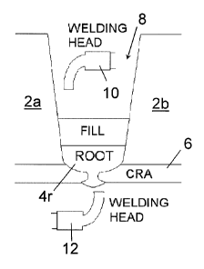
Forming a high quality root weld 4r is of critical importance. A first welding
station is
provided for forming the root weld between the pipe sections 2a, 2b. The pipes
are aligned and
held in place by means of an internal line up clamp 14 (an example of which is
shown in Figure
8a). The welding station includes an exterior welding apparatus including two
external GMAW
(MIG) welding heads arranged 180 degrees apart around the pipe-sections (i.e.
on opposite sides
of the pipes 2). Only one such external welding head 10 is shown in Figures
4a, 4b. The welding
heads 10 are mounted on an external guiding apparatus clamped to the exterior
of the pipes in a
manner well known in the art (such as a "bug-on-band" systems). In use, the
heads 10 are guided
along the joint 8 to be welded partly by the exterior guiding apparatus, which
includes a bevel
tracking system (although in other embodiments, a weld operator may assist in
the tracking and
tracing of the bevel). Each exterior welding head 10 has one welding torch
(but in other
embodiments, each head might have two or more torches), in the form of a
consumable electrode
torch using filler wire. The external welding heads 10 are arranged to weld
simultaneously the
pipe sections together from outside the pipe sections to form a weld joint 4.
Given that the weld
is formed around the circumference of the pipes, the welding process is
typically referred to as
girth-welding.
At the first welding station, there is also provided an interior welding
apparatus. The
interior welding apparatus includes the ILUC (internal line-up clamp - not
shown in Figures 4a,
4b) mentioned above which holds the pipes in place. The ILUC also holds an
internal guiding
apparatus 16 (shown in Figure 8b) and a single internal welding head 12. The
internal welding
head 12 carries a single Gas Tungsten Arc Welding GTAW (TIG) welding torch,
using a non-
consumable Tungsten electrode. The internal GTAW welding head is arranged to
operate under
the protection of inert gas, typically a mixture including Argon. In use, the
internal welding head
12 is partly guided along the joint to be welded by the internal guiding
apparatus 16 and partly by
a welding operator. The welding operator can control movement of the welding
torch across the
width of the bevel (in a direction parallel to the axis of the pipes) by means
of a joystick, whilst
monitoring the position of the welding by means of a camera system mounted on
the ILUC which
provides video feedback on a video display viewed by operator. The interior
welding apparatus
is arranged as to define a central open region for accommodating an umbilical
assembly 20. In an
alternative embodiment, shown in Figure 8c, the interior welding apparatus is
provided on a
carriage 18 that is moveable independently of the internal line-up clamp.
CA 02782165 2016-10-25
- 13 -
The method of the embodiment includes using external welding heads 10 to
perform an
external weld pass on the root of the joint 8 to be welded during which weld
material is
deposited in the root of the joint, thereby forming a root weld 4r. Two
separate external welding
heads 10 are simultaneously used to deposit weld material in the root at
different circumferential
positions around the pipes 2. The root weld 4r then cools and starts to
solidify. Whilst the
external heads 10 are used to perform fill passes to form the higher layers
(the hot pass zones
4h1, 4h2), the internal welding head 12 is used to perform an internal weld
pass on the root weld
4r. The internal welding torch on the welding head travels at 25 cm/min and
operates at 150A.
This internal weld pass melts the root weld deposited by the external welding
apparatus, without
using any additional filler material. The root weld 4r will typically be
remelted, because the
weld 4r will by then have solidified, or at least partly solidified. The
internal weld pass melts
the root weld and surrounding material to a depth of about 1.5 - 2mm. The
resultant bead has a
width of about 8 - lOmm. This makes it relatively tolerant to variations in
its lateral position,
and makes it relatively easy for the welding operator to guide the internal
welding apparatus
with sufficient accuracy.
Figure 4a represents the performance of external weld pass, whereas Figure 4b
represents the performance of the internal weld pass.
Changing of the shape of the root weld 4r has several potential benefits and
can improve
the quality of the root weld. Quality of a root weld formed solely by means of
an external
welding process can be adversely affected by factors such as:
= Hi-lo being too high (pipe wall misalignment, resulting from differing
shapes of pipe
sections and/or misalignment of the axes of the pipes), affecting structural
integrity;
= Lack of root weld penetration, affecting structural integrity;
= Excess of root weld penetration, making the weld more susceptible to
corrosion; and
= Root weld concavity, rough shape or the weld and/or minor defects in the
weld
shape, making the weld more susceptible to corrosion and/or affecting
structural integrity.
A hi-lo mismatch can produce a step between the adjacent pipe-sections, which
can lead
to stress concentration during fatigue loading and therefore potentially
affect the mechanical and
structural integrity of the weld joint. An internal weld pass which melts and
flattens the weld in
the region of the step can therefore have the affect of improving the quality
and structural
strength of the weld.
CA 02782165 2016-10-25
=
- 14 -
If the external weld pass produces a root weld which is not fully fused to the
pipes, it is
likely that the lack of fusion will be near the interior surface of the pipes.
The internal weld pass
can therefore remelt the root weld so that it becomes better fused to the
pipes. It should be noted
that remelting of the root weld 4r does not adversely affect the mechanical
properties of the root
weld.
If the external weld pass produces a root weld with a rough shape, for example
having
overhangs or concavities, or a large protrusion into the interior of the pipe,
the step of performing
the internal weld pass on the root weld smoothes and flattens the shape of the
root weld, making
it less susceptible to corrosion. Minor defects in the weld, such as small
cracks on or near the
interior surface of the pipes can be removed by means of remelting the weld.
Some of the above described factors that affect weld quality and acceptability
and the
solutions provided by the present embodiment will now be described with
reference to Figures 5a
to 7c. Figure 5a is a photograph of the interior surface showing the
progression of an internal
weld (from left to right). Figure 5b shows a cross-section (across surface B-B
indicted in Figure
5a) of the pipes 2a, 2b in a region of the weld-root 4r that has not yet been
subjected to the
internal weld pass and Figure 5c shows a cross-section (across surface C-C
indicted in Figure 5a)
of the pipes 2a, 2b in a region of the weld-root 4r that has been subjected to
the internal weld
pass. The cross-section of Figure 5b shows that there is a hi-lo of about 3mm.
After the internal
GTAW pass the weld bead 4i on the internal surface changes the shape of the
weld 4 so that the
hi-lo step is changed into a gradual incline.
Figure 6a is a photograph of the interior surface showing the progression of
an internal
weld (from left to right) on a different pair of pipe sections 2a, 2b. Figure
6b shows a cross-
section (across surface B-B indicted in Figure 6a) of the pipes 2a, 2b in a
region of the weld-root
4r that has not yet been subjected to the internal weld pass and Figure 6c
shows a cross-section
(across surface C-C indicted in Figure 6a) of the pipes 2a, 2b in a region of
the weld-root 4r that
has been subjected to the internal weld pass. The cross-section of Figure 6b
shows that there is a
lack of penetration into the CRA layer 6 by the external weld 4e formed by the
external pass,
such a lack of penetration for example being due to a high root face. After
the internal GTAW
pass, the weld 4i on the internal surface melts the CRA layer 6 and the
external weld 4e so that
the weld 4 penetrates completely.
= CA 02782165 2016-10-25
- 15 -
Figures 7a to 7c are photographs showing the internal surface and root weld 4r
before and
after the internal TIG pass in the presence of a 3 mm hi-lo and irregular and
excessive penetration
of weld material. The cross-section of Figure 7b (taken across surface B-B
indicted in Figure 7a)
shows that there is a hi-lo of about 3mm and an overhang of weld material with
a very rough and
sharp-edged profile. Especially insofar as the right-hand pipe section 2b is
concerned, there is an
excessive amount of penetration of the weld material. As shown in Figure 7c
(which shows a
cross-section across surface C-C indicted in Figure 7a), after the internal
GTAW pass, the weld
bead 4i on the internal surface changes the shape of the weld 4 so that the hi-
lo step is changed
into a gradual incline and the overhang and rough shape of the weld is
flattened and smoothed.
Thus, the shape of the root weld can be significantly improved to provide
enhanced
fatigue performance, increase the prospects of a full fusion of the root weld,
and reduce the
presence of defects in the pipe joint.
After the internal weld pass has been completed the root weld solidifies
again. The
internal welding step may include making one, two or even three passes with
the internal welding
apparatus. After the internal weld passes on the root weld have been
completed, non-destructive
testing (NDT) is performed at the first welding station. The NDT tests include
both inspecting
the root weld with ultrasonic sensors and performing a visual inspection of
the interior of the
pipes with the use the camera system mounted on the ILUC. If a weld defect is
detected, the
defect may be one that is able to be repaired simply by performing one or more
further internal
weld passes, and using the GTAW to remelt the root weld. In contrast to the
normal weld passes
made during the method of this embodiment of the invention, the one or more
internal weld
passes used to repair the root weld may include adding weld filler material.
Following NDT operations, and repair processes if deemed necessary, at the
first station,
the pipe sections then be moved to the subsequent welding stations where yet
more external
weld passes are performed including the final cap weld.
The method and apparatus of the above-described embodiment has many
advantageous
features:
= The first external pass can be deposited much more quickly with two heads
being
used simultaneously and higher travel speeds. This is made possible because,
consistently
achieving full penetration with this external bead is not required, since full
fusion can be
achieved internally by the GTAW pass.
CA 02782165 2016-10-25
- 16 -
= Significantly reduced welding cycle times and increased productivity.
= High assurance of full bead fusion and full penetration is achieved
through the
remelting of the inner 1.5 to 2 mm of the internal surface by the GTAW
torches.
= The profile of the internal bead is extremely flat and optimal for
corrosion and/or
fatigue resistant properties.
= The reshaping of the internal bead shape can be achieved in all welding
positions,
irrespective of pipe orientation.
= The technique has a high tolerance to variations in pipe fit-up. Less
time therefore is
required in the fitting together of pipes at the first station. Pipe
tolerances also become less
critical in the procurement process of clad pipe, as pipes can be joined with
sufficient weld
quality with hi-lo values of up to 3 mm, which might allow for a cost
reduction in these items.
= The GTAW process used on the internal weld pass is relatively simple,
does not
require filler wire, and has high reliability.
= Prior art techniques for welding clad pipe have required the bevel to be
relatively
wide in order to achieve full penetration from the first external pass.
Because achieving full
penetration externally is not critical when an internal GTAW pass is
subsequently applied, the
overall width of the bevel can be reduced. This has the benefit of reducing
the number of fill
passes. It also has the potential of reducing the defect rate in the fill
passes, because there is a
greater tendency for lack of fusion defects to be produced in the higher
passes with the increased
oscillation widths required for wider bevels.
= The use of GTAW internally allows a degree of repair of the root bead in
the event of
rejection since the bead can be remelted by a further pass. In prior art
techniques, there has been
no repair option in the event of rejection of the root bead and consequently
the whole weld is
typically cut-out.
= Since the root pass is remelted, there is no need for purging of the weld
area before
the external weld passes. The internal GTAW process gives a final weld bead
surface with low
oxidation and enhanced corrosion properties.
The apparatus may of course also be used with different bevel geometries. The
bevel
geometry may be adapted as appropriate. Factors that should be borne in mind
include: 1) the
root face may need to be thick enough to sustain the first external weld, if
copper backing shoes
are not used; 2) dimension C must be thicker than the clad layer, so as to
reduce involve CRA
CA 02782165 2016-10-25
- 17 -
material during the welding of the first external pass; 3) there may be a need
to provide an
internal groove for the internal welding apparatus and to use filler material
on the internal pass, in
which case dimension D and angle E will need to be sized to allow the TIG arc
to reach fully into
the groove, but not too large to avoid the deposition of excessive quantity of
filler metal.
The apparatus of the above-described embodiment can be used on a bevel
geometry as
shown in Figure 3b. The bevel shown in Figure 3b may be defined by a set of
parameters as
follows: A = 3.2 mm; B = 2.3 mm; C = 3.8 mm; D = 4.0 mm; E = 15'; G = 3'; R1=
3.2 mm; and
R2 = 2.4 mm. It will be observed that such parameters require the use of
filler material on the
internal weld pass(es) in order to bridge the groove formed between the pipe
sections 3a, 3b on
the interior surface of the pipes. The choice of bevel dimensions and the
manner in which the
internal and external welding is performed needs careful consideration when
performing
heterogeneous welding between CS and CRA materials, especially in view of the
possible
negative consequences on the metallurgy of the resulting welded joint. For
example, high Ni
alloys are often subject to hot cracking due to: 1) large amplitude of the
solidification gap,
worsened by dilution with different materials (such as carbon steel); 2)
presence of impurities (S,
P, low-melting metalloid) in the weld area; and 3) dilution, Ni percentage
dropping to the range
30%-50% results in a high susceptibility to hot cracking. It is believed that
in practice, it will be
permissible (in terms of the risk to structural integrity) to weld a CS base
material with CRA
filler material, but not vice versa. In any case, there are benefits in
reducing the amount of
dilution of the CRA material in order not to prejudice the anti-corrosion
properties of the CRA
material. In the present embodiments, the geometry of the bevel, allows the
external weld to be
performed on CS base material using CS filler wire, and allows the internal
weld to be
subsequently performed on CRA base material using a suitable filler wire (for
example "Inconel"
wire, an austenitic nickel-chromium-based super-alloy made by Special Metals
Corporation, of
New York, US).
It should be noted that the choice of bevel may also affect the interaction
between the
internal and external arcs (GTAW and GMAW) if such arcs are used
simultaneously and cross
the same position at the same time. The arcs may interact by means of the
magnetic field related
to one torch, disturbing and causing deviation in the other (magnetic blow
effect). Simultaneous
use of internal and external arcs at the same position could overheat the
material being welded
potentially leading to a burn through, that could damage either or both of the
torches and/or
CA 02782165 2016-10-25
=
- 18 -
produce an unacceptable defect. However, one layer of weld deposit has been
found to provide
sufficient protection against undesirable effects as a result of simultaneous
use of both internal
and external arcs.
Whilst the present invention has been described and illustrated with reference
to particular
embodiments, it will be appreciated by those of ordinary skill in the art that
the invention lends
itself to many different variations not specifically illustrated herein. By
way of example only,
certain possible variations will now be described.
The apparatus of the above described embodiment may be used to weld together
standard
(non-clad) steel pipes. The embodiment has for example application on carbon
steel catenary
risers which are highly fatigue sensitive.
The internal welding pass to perform root weld shape control can be performed
at any
point between depositing the external root pass to full completion of all
external welding passes.
There is no need for the internal weld pass to be performed at the first
welding station.
The internal welding means may, instead of comprising a Gas Tungsten Arc
Welding
GTAW (TIG) welding torch, comprise a plasma-welding torch.
There may be further developments that could be made to improve effectiveness
and
reliability, which are set out below:
= Evaluation of PAW (or Plasma-MIG Hybrid) technology for the improvement
of
travel speed, penetration control and electrode durability for the internal
weld pass.
= Evaluation of TIG hot-wire process to improve filler metal deposition, if
required for
the internal weld pass.
= Evaluation and study of special fluxes available on the market, which
permit an
increase of penetration with TIG process. This could help to solve eventual
problems
due to the wettability of different materials during heterogeneous welding.
= Evaluation of different gas mixture compositions with the addition of small
quantities
of H2, that should improve penetration and limit bead surface oxidation.
Where in the foregoing description, integers or elements are mentioned which
have
known, obvious or foreseeable equivalents, then such equivalents are herein
incorporated as if
individually set forth. Reference should be made to the claims for determining
the true scope of
the present invention, which should be construed so as to encompass any such
equivalents. It
will also be appreciated by the reader that integers or features of the
invention that are described
CA 02782165 2016-10-25
- 19 -
as preferable, advantageous, convenient or the like are optional and do not
limit the scope of the
independent claims. Moreover, it is to be understood that such optional
integers or features,
whilst of possible benefit in some embodiments of the invention, may not be
desirable, and may
therefore be absent, in other embodiments.