Note: Descriptions are shown in the official language in which they were submitted.
CA 02782193 2016-05-24
1
Description
RECEPTION APPARATUS, RECEPTION METHOD, TRANSMISSION APPARATUS,
TRANSMISSION METHOD, PROGRAM, AND BROADCAST SYSTEM FOR DATA
CONTENT
Technical Field
[0001] The present invention relates to a reception apparatus, a reception
method, a
transmission apparatus, a transmission method, a program, and a broadcast
system, and
more particularly, to a reception apparatus, a reception method, a
transmission
apparatus, a transmission method, a program, and a broadcast system that are
suitable
for use in a case of executing data content while interlocking with the
progress of AV
content corresponding to so-called television programs in digital television
broadcast,
for example.
Background Art
[0002] From the past, the digitization of television broadcast has been
promoted in Japan
and terrestrial digital broadcast, BS digital broadcast, and the like are
widely diffused.
In addition, the digital television broadcast such as terrestrial digital
broadcast realizes
not only broadcast of AV content corresponding to so-called television
programs but
also so-called data content. Using data content, display of information
related to a
television program being broadcast (AV content), display of information that
is not
related to a television program being broadcast (announcement of another
television
program, news, weather report, traffic information, etc.), and execution of
applications
that interlock with a television program being broadcast (AV content) are
enabled (see,
for example, Patent Literature 1).
[0003] It should be noted that the broadcast of data content in Japan is
realized by securing a
band for data broadcast in a broadcast band for digital television broadcast
in advance
at a time of digitizing television broadcast, and broadcasting data content
using this
band.
[0004] Incidentally, in the digital television broadcast in the United
States, one corre-
sponding to the data broadcast in the digital television broadcast in Japan
has not been
realized. In other words, the broadcast band in the current digital television
broadcast
in the United States is occupied by a video band, an audio band, and a control
in-
formation band as shown in Fig. 1A, and a band for broadcasting data content
is not
provided. Therefore, to secure a band for broadcasting data content in the
limited
broadcast band of the digital television broadcast, the video band and the
audio band
are necessary to be reduced in size as shown in Fig. 1B.
Citation List
2
WO 2011/074218 PCT/JP2010/007194
Patent Literature
[0005] PTL 1: Japanese Patent Application Laid-open No. 2006-50237
Summary of Invention
[0006] However, to reduce the sizes of the video band and the audio band to
secure the band
for broadcasting data content leads to the deterioration of image quality and
sound
quality of television programs, and results in undesirable performance.
[0007] In addition, since a retransmission system of digital television
programs using a
CATV (cable-TV) network is widely used in the United States, the following
problems
may also be caused.
[0008] Fig. 2 shows an example of a structure of a retransmission system of
digital
television programs using a CATV network.
[0009] The retransmission system mainly includes a broadcast or output
apparatus 1, a
CATV retransmission apparatus 2, a CATV network 3, a digital television set 4,
a set
top box (STB) 5, and a television set 6.
[0010] The broadcast apparatus 1 installed in a broadcast station or the
like broadcasts, or al-
ternatively, outputs to a transmitter, a digital television broadcast signal.
For example,
the broadcast may be by terrestrial waves or satellite waves. The CATV
retransmission
apparatus 2 installed in a cable TV station or the like receives digital
television
broadcast that has been broadcast, and removes unnecessary information
therefrom and
adds information specific to CATV thereto, to thereby retransmit the resultant
to the
digital television set 4, the set top box 5, and the like via the CATV network
3.
[0011] The CATV retransmission apparatus 2 includes a tuner 11, a PID
filter 12 for
filtering a packet of a predetermined packet ID, a CATV-specific signal
generation
section 13, a multiplexing section 14, and a modulation section 15.
[0012] The tuner 11 receives and demodulates a digital television broadcast
signal of each
channel and outputs a resultant TS (transport stream) to the PID filter 12.
The PID
filter 12 removes a packet (that is not related to AV content as television
program) cor-
responding to a predetermined packet ID from the TS and outputs the TS to the
mul-
tiplexing section 14. The CATV-specific signal generation section 13 generates
a
packet storing information specific to a relevant CATV station and outputs the
packet
to the multiplexing section 14. The multiplexing section 14 multiplexes the
output of
the PID filter 12 and the output of the CATV-specific signal generation
section 13 and
outputs the resultant to the modulation section 15. The modulation section 15
modulates the output of the multiplexing section 14 by a modulation system
suitable
for the CATV network 3 and retransmits the resultant to the digital television
set 4, the
set top box 5, and the like via the CATV network 3.
[0013] The digital television set 4 that supports CATV receives the TS of
the retransmitted
CA 02782193 2012-05-28
3
WO 2011/074218 PCT/JP2010/007194
digital television broadcast via the CATV network 3 and decodes the TS, and
then
displays a resultant video and outputs audio at the same time.
[0014] The set top box 5 that supports CATV receives the TS of the
retransmitted digital
television broadcast via the CATV network 3 and decodes the TS, and then
outputs
resultant video and audio signals to the television set 6 via an HDMI cable or
the like.
The television set 6 displays the video and outputs the audio based on the
video signal
and the audio signal input from the set top box 5 via the HDMI cable or the
like.
[0015] As described above, in the CATV retransmission apparatus 2, a packet
(that is not
related to AV content as television program) corresponding to a predetermined
packet
ID is removed from the TS of the digital television broadcast signal by the
PID filter
12. As a result, even if a band for broadcasting data content is secured in
the broadcast
band as shown in Fig. 1B, there may be caused a case where packets storing the
data
content are removed by the PID filter 12.
[0016] In view of the circumstances as described above, it is desirable to
realize a service of
data content that can interlock with the progress of a television program
without
providing a band for data broadcast in a broadcast band for digital television
broadcast.
[0017] According to an embodiment of the present invention, the application
program can
be controlled interlocking with the progress of the AV content such as a
television
program without providing a band for data broadcast in a broadcast band for
digital
television broadcast.
[0018] According to another embodiment of the present invention, there is
provided a
reception apparatus that receives an audio and/or video (AV) content, the
apparatus
including: an extraction section to extract trigger information (or other
information
regarding the data content) from the AV content, the trigger information being
related
to an application program that is executed interlocking with a progress of the
AV
content, the trigger information including a trigger type; and a control
section to
control one of an activation of the application program, a dispatch of an
event of the
application program being executed, and an end of the application program
being
executed in accordance with the trigger type included in the extracted trigger
in-
formation.
[0019] According to another embodiment of the present invention, there is
provided a
transmission apparatus that transmits an audio and/or video (AV) content, the
apparatus including a transmission section to store trigger information in the
AV
content to be transmitted, the trigger information being related to an
application
program that is executed by a reception apparatus, interlocking with a
progress of the
AV content. The trigger information includes a trigger type that includes at
least one of
an application activation of instructing an activation of the application
program, an ap-
plication event of instructing a dispatch of an event of the application
program being
CA 02782193 2012-05-28
4
WO 2011/074218 PCT/JP2010/007194
executed, and an application end of instructing an end of the application
program being
executed.
[0020] According to yet another embodiment of the present invention, there
is provided an
apparatus for providing access to data content on a server. The apparatus may
include
an insertion unit configured to insert information regarding the data content
into a
digital television broadcast signal, the digital television broadcast signal
not including
the data content; and an output unit configured to output the digital
television
broadcast signal for broadcast.
[0021] According to yet another embodiment of the present invention, there
is provided an
apparatus for receiving data content. The apparatus may include a receiving
unit
configured to receive, over a first communication channel, a digital
television
broadcast signal containing information regarding the data content accessible
over a
second communications channel; and an extracting unit configured to extract
the in-
formation regarding the data content from the digital television broadcast
signal.
[0022] According to yet another embodiment of the present invention, there
is provided a
method for providing access to data content on a server. The method may
include
inserting information regarding the data content into a digital television
broadcast
signal, the digital television broadcast signal not including the data
content; and
outputting the digital television broadcast signal.
[0023] According to yet another embodiment of the present invention, there
is provided a
method for receiving data content. The method may include receiving, over a
first
communication channel, a digital television broadcast signal containing
information
regarding the data content accessible over a second communications channel;
and ex-
tracting the information regarding the data content from the digital
television broadcast
signal.
[0024] According to yet another embodiment of the present invention, there
is provided a
system for delivering data content. The system may include a broadcasting
apparatus
configured to broadcast a digital television broadcast signal over a first
communication
channel, the digital television broadcast signal including information
regarding the data
content and not including the data content; and a server configured to
transmit the data
content over a second communications channel in response to a request for the
data
content.
[0025] According to yet another embodiment of the present invention, there
is provided a
computer-readable storage medium storing instructions which, when executed by
a
processor, cause a computer to perform a method. The method may include
inserting
information regarding data content into a digital television broadcast signal,
the digital
television broadcast signal not including the data content; and outputting the
digital
television broadcast signal.
CA 02782193 2012-05-28
CA 02782193 2015-08-14
[0026] According to yet another embodiment of the present invention, there
is provided a
computer-readable storage medium storing instructions which, when executed by
a
processor, cause a computer to perform a method. The method may include
receiving,
over a first communication channel, a digital television broadcast signal
containing in-
formation regarding the data content; extracting the information regarding the
data
content from the digital television broadcast signal; and acquiring the data
content over
a second communications channel using the information regarding the data
content.
Brief Description of Drawings
[0027] [fig.1] Figs. lA and 1B are diagrams each showing a broadcast band for
digital television
broadcast.
[0028] [fig.2]Fig. 2 is a diagram showing an example of a structure of an
existing CATV re-
transmission system.
[0029] [fig.31Fig. 3 is a diagram showing a structural example of a broadcast
system to which
an embodiment of the present invention is applied.
[0030] [fig.4]Fig. 4 is a block diagram showing a structural example of a
reception apparatus
to which the embodiment of the present invention is applied.
100311 Ifig.5]Fig. 5 is a diagram showing a concept of transmitting a PCR
packet of a TS
including trigger information.
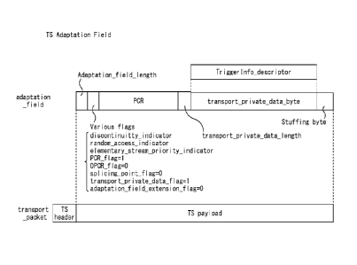
[0032] [fig.6]Fig. 6 is a diagram showing a specific arrangement of the
trigger information in
the PCR packet.
[0033] [fig.7[Fig. 7 is a diagram showing items included in the trigger
information.
[0034] [fig.8[Fig. 8 is a diagram showing an example of a syntax of the
trigger information.
[0035] [fig.9]Fig. 9 is a flowchart for describing trigger information
processing.
[0036] [fig.10] Figs. 10A and 10B are each diagrams for describing
distribution of access to a server.
[0037] [fig.11]Fig. 11 is a display example of a screen at a time when a data
broadcast ap-
plication is executed.
[0038] [fig.12]Fig. 12 is another display example of the screen at the time
when the data
broadcast application is executed.
[0039] [fig.13] Figs. 13A and 13B are diagrams each showing an example in
which the trigger in-
formation is embedded in a base band video signal.
[00401 Ifig.141Fig. 14 is a block diagram showing a structural example of a
computer.
Description of Embodiments
[0041] Hereinafter, best modes for carrying out the present invention
(hereinafter, referred to
as embodiments) will be described in detail with reference to the drawings.
(1. First embodiment)
Structural example of broadcast system
100421 Fig. 3 shows a broadcast system 30 as this embodiment. The broadcast
system 30
6
WO 2011/074218 PCT/JP2010/007194
realizes a service of data content that can interlock with AV content of
television
programs without providing a band for broadcasting the data content in a
broadcast
band for digital television broadcast in the current United States, for
example.
[0043] The broadcast system 30 includes a broadcast apparatus 41 and a
server 42 that are
installed on a broadcast station side, and a reception apparatus 60 installed
on a
receiver side.
[0044] The broadcast apparatus 41 outputs or transmits a digital television
broadcast signal.
It is assumed that a broadcast band of the digital television broadcast signal
is occupied
by a video band, an audio band, and a control information band as shown in
Fig. 1A
and a band for broadcasting data content is not provided.
[0045] Further, the broadcast apparatus 41 stores or inserts, at a
predetermined timing, in-
formation regarding the data content, such as trigger information, in a packet
that is
defined not to be removed by CATV apparatus, such as a Program Clock Reference
(PCR) packet in a TS packet constituting a TS (transport stream) of the
digital
television broadcast signal. Then, the broadcast apparatus 41 transmits the
digital
television broadcast signal storing the trigger information.
[0046] Here, the information regarding the data content may entirely be
trigger information
including information indicating an execution timing of a data broadcast
content, in-
formation indicating an acquisition source of a data broadcast content, and
the like.
The trigger information will be described in detail with reference to Figs. 5
to 8.
[0047] The server 42 supplies a data broadcast content or the like to the
reception apparatus
60 in response to a request from the reception apparatus 60 that accesses the
server 42
via an Internet 50.
[0048] The reception apparatus 60 receives the digital television broadcast
signal that is
broadcast from the broadcast apparatus 41 over a first communications channel,
such
as a terrestrial RF broadcast, and acquires video and audio of an AV content
corre-
sponding to a television program, to thereby output the acquired video and
audio to a
monitor (not shown). Further, the reception apparatus 60 accesses the server
42 over a
second communications channel, such as via the Internet 50, and acquires a
data
broadcast content. It should be noted that the reception apparatus 60 may
exist indi-
vidually or may be incorporated into a television set or a video recorder, for
example.
Structural example of reception apparatus
[0049] Fig. 4 shows a structural example of the reception apparatus 60. The
reception
apparatus 60 includes a receiving unit such as a tuner 61, an extracting unit
such as a
demultiplexing section 62, an audio decoder 63, an audio output section 64, a
video
decoder 65, a trigger detection section 66, a video output section 67, a
controller 68, a
memory 69, an operation section 70, a recording section 71, a communication
I/F 72,
and a browser 73.
CA 02782193 2012-05-28
7
WO 2011/074218 PCT/JP2010/007194
[0050] The tuner 61 receives and demodulates a digital television broadcast
signal corre-
sponding to a channel selected by a user and outputs a resultant TS to the
demul-
tiplexing section 62. The demultiplexing section 62 demultiplexes the TS input
from
the tuner 61 into an encoded audio signal, an encoded video signal, and a
control
signal, and outputs the encoded audio signal, the encoded video signal, and
the control
signal to the audio decoder 63, the video decoder 65, and the controller 68,
re-
spectively.
[0051] Further, the demultiplexing section 62 extracts a PCR packet
including the trigger in-
formation arranged in the TS and outputs the PCR packet to the controller 68.
[0052] The audio decoder 63 decodes the input encoded audio signal and
outputs a resultant
audio signal to the audio output section 64. The audio output section 64
outputs the
input audio signal to a subsequent stage (for example, speaker).
[0053] The video decoder 65 decodes the encoded video signal thus input and
outputs a
resultant video signal to the trigger detection section 66 and the video
output section
67. The trigger detection section 66 constantly monitors the input video
signal and
detects trigger information embedded in the video signal (which corresponds to
another transmission method (described later) different from the transmission
method
in the case where the trigger information is stored in the PCR packet). The
video
output section 67 outputs the video signal input from the video decoder 65 to
a
subsequent stage (for example, monitor). Further, the video output section 67
combines
a video of a data broadcast content that is input from the browser 73 and the
video
signal input from the video decoder 65 and outputs the combined resultant to
the
subsequent stage. It should be noted that the output from the audio output
section 64
and the video output section 67 to the subsequent stages can be performed
using an
HDMI (High-Definition Multimedia Interface) cable.
[0054] The controller 68 controls the entire reception apparatus 60 by
executing a control
program recorded in the memory 69. Further, the controller 68 controls
acquisition, ac-
tivation, event dispatch, end, and the like of an application program for
implementing a
data broadcast content that interlocks with a television program based on the
trigger in-
formation input from the demultiplexing section 62 (or trigger detection
section 66).
[0055] In the memory 69, a control program executed by the controller 68 is
recorded. The
control program can be updated based on a digital television broadcast signal
or update
data acquired via the Internet 50. The operation section 70 receives various
operations
from the user and notifies the controller 68 of operation signals
corresponding to the
various operations.
[0056] The recording section 71 stores a downloaded data broadcast
application in a built-in
recording medium in a case where the data broadcast application is distributed
using a
digital television broadcast signal.
CA 02782193 2012-05-28
8
WO 2011/074218 PCT/JP2010/007194
[0057] The communication I/F 72 is connected to the server 42 via the
Internet 50 under the
control of the browser 73. The browser 73 acquires an application program for
data
broadcast (hereinafter, referred to simply as data broadcast application) from
the server
42 via the communication I/F 72 and the Internet 50 under the control of the
controller
68.
Details of trigger information
[0058] Fig. 5 shows a concept of a case where the trigger information
stored in PCR packets
of a TS is transmitted. As shown in Fig. 5, the trigger information is not
stored in all
PCR packets but stored in PCR packets at only adequate timings for
interlocking with
an AV content corresponding to a television program. Since the PCR packet is a
type
of packet defined to remain in a transport stream after processing by a CATV
re-
transmission system, the PCR packet passes through a PID filter 12 of a CATV
re-
transmission apparatus 2 shown in Fig. 2 in general. The trigger information
can thus
be notified to a reception apparatus using a CATV network (digital television
set 4 of
Fig. 2).
[0059] It should be noted that depending on the contents of the trigger
information, the same
trigger information is transmitted a plurality of number of times in
consideration of a
case where the trigger information is not received by the reception apparatus
60.
[0060] Fig. 6 shows a position at which the trigger information is stored
in a PCR packet.
The PCR packet is obtained by storing a PCR in "adaptation field" of a TS
packet, and
the trigger information (TriggerInfo descriptor) is stored in
"transport private data byte" subsequent to the PCR. It should be noted that
in a case
where the trigger information is stored, "transport private data flag" of
"Various
flags" provided before the PCR is set to 1.
[0061] Fig. 7 shows an example of information items included in the trigger
information.
[0062] A trigger ID is information for identifying relevant trigger
information. In the case
where the same trigger information is transmitted a plurality of number of
times, the
trigger IDs of the respective pieces of trigger information are the same.
Further, the
same trigger ID is imparted to pieces of trigger information in which only
server access
distribution parameters described later are different. A trigger type
indicates that the
trigger information is in any state of "application execute" (that instructs
acquisition
and activation of data broadcast application), "application terminate" (that
instructs end
of data broadcast application being executed), "inject-event" that instructs
dispatch of
event (update of displayed contents etc.) in data broadcast application being
executed),
and "precache" (that instructs only acquisition of data broadcast
application).
[0063] An application ID is information for identifying a data broadcast
application corre-
sponding to the trigger information. An application type is information
indicating a
type of the data broadcast application (for example, html and java)
corresponding to
CA 02782193 2012-05-28
9
WO 2011/074218 PCT/JP2010/007194
the trigger information. A business company ID is information for identifying
a
business company (broadcast station etc.) that performs a service of executing
the data
broadcast application corresponding to the trigger information. An application
URL
(Uniform Resource Locator) is a URL of an acquisition source, that is,
information
regarding a location, of the data broadcast application (in this case, server
42) in the
case where the trigger type is "application execute " or "precache". An
accumulation
application ID is described only when an accumulated data broadcast
application to be
activated (already acquired data broadcast application) is designated without
instantly
acquiring a data broadcast application in the case where the trigger type is
"application
execute ".
[0064] An automatic activation flag is described in the case where the
trigger type is "ap-
plication execute" and is set to on or off. When the automatic activation flag
is on,
"automatic execute" (to automatically activate data broadcast application) is
set. When
the automatic activation flag is off, "manual activation" (to prompt user to
make
operation input and activate data broadcast application in accordance with
operation
input) is set.
[0065] An application end time is information that indicates a time at
which the data
broadcast application being executed is ended in the case where the trigger
information
whose trigger type is "application terminate" is not received.
[0066] A server access distribution parameter is a value N (integer of 2 or
more) for dis-
tributing access, or controlling attempts to access server 42 among a
plurality of
receiver devices so as to avoid concentration on a certain period of time when
each
reception apparatus 60 that has received the trigger information acquires a
data
broadcast application from the server 42. For example, to distribute access to
the server
42 from a possible large number of reception apparatuses 60 into 4 times, it
is only
necessary to transmit the same trigger information 4 times, and set the server
access
distribution parameter N of the first trigger information to 4, the server
access dis-
tribution parameter N of the second trigger information to 3, the server
access dis-
tribution parameter N of the third trigger information to 2, and the server
access dis-
tribution parameter N of the fourth trigger information to 1. That is, the
access dis-
tribution parameter may be sequentially inserted or transmitted as a plurality
of values.
It should be noted that in a case where the trigger information is not related
to the
access to the server 42, the server access distribution parameter N has only
to be set to
1. Details of the server access distribution parameter will be described later
with
reference to Figs. 10.
[0067] An application name is a name of a data broadcast application to be
presented to the
user in a case where the automatic activation flag is set to "manual
activation". An
event ID is information for identifying an event in a case where the trigger
type is set
CA 02782193 2012-05-28
10
WO 2011/074218 PCT/JP2010/007194
to "inject-event". It should be noted that the trigger information does not
include all the
items described above generally, but includes only items necessary at that
timing.
[0068] Fig. 8 shows an example of a syntax of the trigger information. It
should be noted
that the syntax of the trigger information is arbitrarily set and is not
limited to that of
Fig. 8.
Description on operation
[0069] Next, an operation at a time when the reception apparatus 60
receives the trigger in-
formation (hereinafter, referred to as trigger information processing) will be
described.
[0070] Fig. 9 is a flowchart for describing the trigger information
processing. The trigger in-
formation processing is executed repeatedly when the user is viewing a
television
program, that is, during a period of time in which a digital television
broadcast signal
is being received.
[0071] In Step Sl, the controller 68 waits until a PCR packet including
trigger information is
received based on an input from the demultiplexing section 62. Then, when the
PCR
packet including trigger information is received, the processing proceeds to
Step S2.
[0072] In Step S2, the controller 68 extracts the trigger information from
the received PCR
packet and judges whether processing of Step S4 and subsequent steps are
already
performed on the trigger information. When it is judged that the processing of
Step S4
and subsequent steps are already performed, the processing returns to Step 1
and
repeats the subsequent steps. Conversely, when it is judged that processing of
Step S4
and subsequent steps are not performed on the trigger information, the
processing
proceeds to Step S3.
[0073] In Step S3, the controller 68 judges whether the current processing
is valid (whether
the processing proceeds to Step S4 and subsequent steps to perform server
access) or
invalid (whether the processing returns to Step 51) based on the server access
dis-
tribution parameter N of the trigger information. It should be noted that in a
case where
the server access distribution parameter N is not described in the trigger
information,
the processing proceeds to Step S4.
[0074] Here, the judgment in Step S3 as to whether the current processing
is valid or invalid
will be described in detail with reference to Figs. 10.
[0075] As shown in Fig. 10B, in order to distribute access to the server 42
from a possible
large number of reception apparatuses 60 into 4 times as an intention of the
broadcast
station side, the same trigger information is transmitted 4 times from the
broadcast
apparatus 41, and the server access distribution parameter N may have a
plurality of
values. For example, the server access distribution parameter N of the first
trigger in-
formation is set to 4, the server access distribution parameter N of the
second trigger
information to 3, the server access distribution parameter N of the third
trigger in-
formation to 2, and the server access distribution parameter N of the fourth
trigger in-
CA 02782193 2012-05-28
11
WO 2011/074218 PCT/JP2010/007194
formation to 1.
[0076] In response to this, the controller 68 of the reception apparatus 60
judges validity or
invalidity based on random numbers or the like under the condition in which
validity is
judged in the probability of 1/N, that is, the server access distribution
parameter N cor-
responds to different probabilities of access to the server.
[0077] As a result, assuming that 10,000 reception apparatuses 60
simultaneously execute
the trigger information processing, the processing is judged to be valid in
about 2,500
(= 10,000/4) reception apparatuses 60 by the first trigger information (server
access
distribution parameter N = 4), additionally in about 2,500 (= 7,500/3)
reception ap-
paratuses 60 by the second trigger information (server access distribution
parameter N
= 3), additionally in about 2,500 (= 5,000/2) reception apparatuses 60 by the
third
trigger information (server access distribution parameter N = 2), and in the
remaining
(= 2,500/1) reception apparatuses 60 by the fourth trigger information (server
access
distribution parameter N = 1). Accordingly, the probability of access by the
plurality of
reception apparatuses increases with successive requests to the server.
[0078] With referring back to Fig. 9, in Step S4, the controller 68 judges
to which of "ap-
plication execute", "inject-event", "application terminate", and "precache" a
trigger
type of the trigger information is set.
[0079] When a trigger type of the trigger information is judged to be
"application execute"
in Step S4, the processing proceeds to Step S5. In Step S5, the controller 68
judges
whether an accumulation application ID is designated in the trigger
information and a
data broadcast application corresponding thereto is already accumulated in the
recording section 71. When it is judged that an accumulation application ID is
not
designated and a data broadcast application corresponding thereto is not
accumulated,
the processing proceeds to Step S6. In Step S6, the controller 68 controls the
browser
73 to access the server 42 that corresponds to an application URL of the
trigger in-
formation and acquire a data broadcast application that corresponds to an
application
ID of the trigger information. Here, in a case where a relevant data broadcast
ap-
plication is already acquired from the server 42 that corresponds to the
application
URL in Step S15 described later and precached, the data broadcast application
is used.
After that, the processing proceeds to step S8.
[0080] Conversely, when it is judged in Step S5 that an accumulation
application ID is
designated in the trigger information and a data broadcast application
corresponding
thereto is already accumulated in the recording section 71, the processing
proceeds to
Step S7. In Step S7, the controller 68 controls the browser 73 to read the
data broadcast
application corresponding to the accumulation application ID of the trigger
information
from the recording section 71. After that, the processing proceeds to Step S8.
[0081] In Step S8, the controller 68 judges whether an automatic activation
flag of the
CA 02782193 2012-05-28
12
WO 2011/074218 PCT/JP2010/007194
trigger information is set to "automatic execute".
[0082] When it is judged in Step S8 that an automatic activation flag of
the trigger in-
formation is not "automatic activation" (that is, the flag is set to "manual
activation"),
the processing proceeds to Step S9. In Step S9, the browser 73 prompts the
user to
make an activation operation of the data broadcast application by displaying,
for
example, "Execute (application name)?" on a screen based on the control by the
controller 68. When it is judged in Step S10 that an activation operation has
been input
by the user in response to the prompt display, the processing proceeds to Step
S12. In
Step S12, the browser 73 activates the data broadcast application that has
been
acquired in Step S6 or read in Step S7 under the control of the controller 68.
After that,
the processing returns to Step 51 and repeats Step 51 and the subsequent
steps.
[0083] It should be noted that when it is judged that an activation
operation is not input by
the user in Step S10 after the prompt display in Step S9 and that a
predetermined
period of time has elapsed without an activation operation input by the user
in Step
S11, the processing returns to Step 51 and repeats Step 51 and the subsequent
steps.
[0084] It should be noted that when it is judged in Step S8 that an
automatic activation flag
of the trigger information is set to "automatic activation", the processing
proceeds to
Step S12. In Step S12, the browser 73 activates the data broadcast application
that has
been acquired in Step S6 or read in Step S7 under the control of the
controller 68. After
that, the processing returns to Step 51 and repeats Step 51 and the subsequent
steps.
[0085] When it is judged in Step S4 that a trigger type of the trigger
information is" inject-
event", the processing proceeds to Step S13. In Step S13, only when an
application ID
of the trigger information is matched to an application ID of the data
broadcast ap-
plication being operated, the controller 68 controls the browser 73 to
dispatch
(execute) an event corresponding to an event ID of the trigger information in
the ap-
plication being operated. After that, the processing returns to Step 51 and
repeats Step
51 and the subsequent steps.
[0086] When it is judged in Step S4 that a trigger type of the trigger
information is "ap-
plication terminate", the processing proceeds to Step S14. In Step S14, only
when an
application ID of the trigger information is matched to an application ID of
the data
broadcast application being operated, the controller 68 controls the browser
73 to end
the application being operated. After that, the processing returns to Step 51
and repeats
Step 51 and the subsequent steps.
[0087] It should be noted that even when the trigger information whose
trigger type is "ap-
plication terminate" is not received, the data broadcast application being
operated is
ended when an application end time comes, the application end time being
described in
the trigger information when the data broadcast application being operated has
been
activated.
CA 02782193 2012-05-28
13
WO 2011/074218 PCT/JP2010/007194
[0088] When it is judged in Step S4 that a trigger type of the trigger
information is
"precache", the processing proceeds to Step S15. In Step S15, the controller
68
controls the browser 73 to access the server 42 corresponding to an
application URL of
the trigger information and acquire a data broadcast application corresponding
to an
application ID of the trigger information, to thereby store the data broadcast
ap-
plication in a storage means such as a cache memory included in the browser
73. After
that, the processing returns to Step 51 and repeats Step 51 and the subsequent
steps.
[0089] When the trigger type is "precache" as in Step S15, before a
broadcast time of a
television program to be interlocked comes, a corresponding data broadcast
application
can be acquired. As a result, the corresponding data broadcast application can
be
executed simultaneously with the start of the television program to be
interlocked. In
addition, an effect of distributing the concentration of access to the server
42 is
expected. The description on the trigger information processing is ended up to
here.
Display example of screen when data broadcast application is executed
[0090] Fig. 11 shows a transition of a screen at a time when a data
broadcast application is
executed interlocking with the progress of a television program in a case
where the
automatic activation flag of the trigger information is off ("manual
activation").
[0091] When the trigger information whose trigger type is "application
execute" and
automatic activation flag is off ("manual activation") is received during a
time when
the user is viewing a television program, a corresponding data broadcast
application is
acquired. Next, an indication that prompts the user to make an activation
operation of
the data broadcast application is displayed to be superimposed on a video of
the
television program. When the user inputs the activation operation in response
to the
prompt, the data broadcast application is activated and the display of the
screen is
changed into a combination of a video corresponding to the data broadcast
application
and the video of the television program.
[0092] When the trigger information whose trigger type is "inject-event" is
received in a
state where the data broadcast application is being executed, an event
corresponding to
an event ID of the trigger information is dispatched in the data broadcast
application
being executed. As a result, an area of the screen display that corresponds to
the data
broadcast application is changed into a video corresponding to the event ID of
the
trigger information.
[0093] After that, when the trigger information whose trigger type is
"application terminate"
is received, the data broadcast application being executed is ended and the
video of the
television program is displayed on the entire screen.
Another display example of screen when data broadcast application is
executed
CA 02782193 2012-05-28
14
WO 2011/074218 PCT/JP2010/007194
[0094] Incidentally, the data broadcast application that is executed
interlocking with the
progress of a television program is not necessarily accompanied with display
on the
screen. With use of such a data broadcast application, that data broadcast
application
can be executed without being known by the user of the reception apparatus 60.
Such a
data broadcast application is applicable to a case where an audience survey of
a
television program is executed, for example. Specifically, whether the
television
program is being viewed is recorded in accordance with the trigger information
whose
trigger type is "inject-event", and the recording results are notified to a
predetermined
server at a predetermined timing, with the result that an audience rating of
the
television program can be investigated at a transmission interval of the
trigger in-
formation whose trigger type is "inject-event".
[0095] Fig. 12 shows a transition of a screen at a time when a data
broadcast application
without display on the screen is executed interlocking with the progress of a
television
program in a case where the automatic activation flag of the trigger
information is on
("automatic activation").
[0096] When the trigger information whose trigger type is "application
execute" and
automatic activation flag is on ("automatic activation") is received during a
time when
the user is viewing a television program, a corresponding data broadcast
application is
acquired and activated. It should be noted that the display on the screen is
not changed
with the video of the television program displayed.
[0097] When the trigger information whose trigger type is "inject-event" is
received in a
state where the data broadcast application is being executed, an event
corresponding to
an event ID of the trigger information is dispatched in the data broadcast
application
being executed. In this case as well, the video of the television program is
left
displayed and the display on the screen is not changed.
[0098] After that, when the trigger information whose trigger type is
"application terminate"
is received, the data broadcast application being executed is ended.
Another transmission method of trigger information
[0099] Though the trigger information is stored in the PCR packet of the TS
to be
transmitted in the above description, the trigger information may be embedded
in a
base band video signal to be transmitted.
[0100] Figs. 13 show two examples in which the trigger information is
embedded in a base
band video signal.
[0101] Fig. 13A shows an example in which the trigger information is
changed into a two-
dimensional barcode and superimposed at a predetermined position in an image
of the
base band video signal (in this case, lower right corner). Fig. 13B shows an
example in
which the trigger information is changed into a video code and combined into
number
lines positioned on a lower side of an image of the base band video signal.
The trigger
CA 02782193 2012-05-28
15
WO 2011/074218 PCT/JP2010/007194
information of Figs. 13A and 13B are detected by the trigger detection section
66 of
the reception apparatus 60.
[0102] Since the trigger information is arranged on the screen of the
television program in
both Figs. 13A and 13B, the trigger information can also be notified to, for
example, a
reception apparatus using a CATV network (for example, television set 6 of
Fig. 2).
[0103] Further, though the trigger information on the screen (two-
dimensional barcode and
video code) can be viewed by the user of the reception apparatus 60 in both
cases of
Figs. 13A and 13B, if this is not desirable, the two-dimensional barcode or
video code
may be displayed after being masked by the same pixels as those around the two-
dimensional barcode or video code.
[0104] As described above, according to the broadcast system 30 to which
the embodiment
of the present invention is applied, the trigger information related to data
broadcast is
embedded in a PCR packet or a base band video signal to be transmitted,
whereas a
data broadcast application is supplied from a server via the Internet. As a
result, a
service of data content that can interlock with television programs can be
realized
without providing a band for data broadcast in a broadcast band for digital
television
broadcast.
[0105] Further, the access to the server can be distributed so as to avoid
the concentration
thereof on a certain period of time.
[0106] In addition, it is also possible to realize a service of data
content that can interlock
with television programs in a case where digital television programs are
retransmitted
via a CATV network, a satellite communication network, or the like.
[0107] Incidentally, a series of processing described above can be executed
by hardware and
can also be executed by software. In a case where a series of processing is
executed by
software, a program constituting the software is installed from a program
recording
medium to a computer incorporated in dedicated hardware, a general-purpose
personal
computer capable of executing various functions by installing various
programs, or the
like.
[0108] Fig. 14 is a block diagram showing a structural example of hardware
of a computer
that executes the series of processing described above by a program.
[0109] In this computer 100, a CPU (Central Processing Unit) 101, a ROM
(Read Only
Memory) 102, and a RAM (Random Access Memory) 103 are connected to one
another via a bus 104.
[0110] An input/output interface 105 is also connected to the bus 104.
Connected to the
input/output interface 105 are an input section 106, an output section 107, a
storage
section (that is, a computer-readable storage medium) 108, a communication
section
109, and a drive 110. The input section 106 includes a keyboard, a mouse, a mi-
crophone, and the like. The output section 107 includes a display, a speaker,
and the
CA 02782193 2012-05-28
CA 02782193 2015-08-14
16
like. The storage section 108 includes a hard disk, a nonvolatile memory, and
the like,
and may store instructions for execution by the CPU. The communication section
109
includes a network interface and the like. The drive 110 drives removable
medium 111
such as a magnet disc, an optical disc, a magneto-optical disc, or a
semiconductor
memory.
[0111] In the computer structured as described above, the CPU 101 loads a
program having
instructions stored in, for example, the storage section 108 in the RAM 103
via the
input/output interface 105 and the bus 104 and executes the program, with the
result
that the series of processing described above is performed.
101121 It should be noted that the program executed by the computer may be
a program with
which processing is performed in a chronological order along the order
described
herein, or may be a program with which processing is performed in parallel or
at a
necessary timing when a calling is made or the like.
[0113] Further, the program may be one processed by one computer or one
processed in a
distributed manner by a plurality of computers. In addition, the program may
be one
transferred to a remote computer and then executed.
[0114] Further, the system herein refers to a plurality of apparatuses, as
a whole.
[0115] It should be noted that the embodiment of the present invention is
not limited to the
embodiment described above and various changes can be made without departing
from
the gist of the present invention.
[0116]
Reference Signs List
[0117] 30 broadcast system
41 broadcast apparatus
42 server
60 reception apparatus
61 tuner
62 demultiplexing section
63 audio decoder
64 audio output section
65 video decoder
66 trigger detection section
67 video output section
68 controller
69 memory
17
WO 2011/074218
PCT/JP2010/007194
70 operation section
71 recording section
72 communication I/F
73 browser
CA 02782193 2012-05-28