Note: Descriptions are shown in the official language in which they were submitted.
CA 02782371 2012-05-30
WO 2011/068771
Attorney DoePCTIUS2010/058263- IVO
Ventilator Respiratory Gas Accumulator with Purge Valve
Intro duction
Medical ventilators can measure the gas mixture concentrations and the
pressure
of the gas sent to the patient during ventilation. Further, medical
ventilators can change
and/or adjust the gas mixture concentrations and gas flow rate of the gas sent
to patient
during ventilation based on received patient information and
ventilator/ventilation
information,
Mixing vessels, also commonly referred to as "accumulators", can be utilized
to
facilitate the mixing of gases and the management of gas delivery pressure.
Accumulators, typically, hold respiratory gas at a high pressure in order to
improve its
delivery control of respiratory gas to the ventilator circuit. The elevated
pressure of the
gas mixture stored in the accumulator makes it prohibitively expensive to
directly
measure the concentrations of gas found within the accumulator using current
gas
mixture monitoring technology. Accordingly, some systems provide conservative
estimates of the time needed for a new gas mixture to replace an old gas
mixture within
the accumulator chamber during ventilation.
Some mixing vessels are not directly in the gas delivery flow path, but are
instead
removed from the gas flow path, such as in a "T" configuration, in order to
reduce the
amount of time necessary to deliver a change in gas mixture to a patient. In
the "T"
configuration, the gas flow path goes across the top of the "T" and the
accumulator is
connected to the flow path by the stem of the "T". The stem of "T" separates
the
accumulator from the flow path. When in this configuration and during the
changing of
a gas mixture, a pocket of air from the accumulator may periodically get
sucked into the
gas flow path changing the gas mixture concentrations sent to the patient.
This periodic
pocket of air or "burp" of air in the gas flow path disrupts the desired gas
mixture to the
patient. Accordingly, while the an accumulator removed from the gas flow path
may
reduce the time necessary to deliver a change in gas mixture to the patient,
it also results
in intermittent burps or pockets of air that do not contain the desired gas
mixture or gas
concentrations during ventilation.
1
CA 02782371 2014-10-15
SUMMarV
This disclosure describes systems and methods for ventilating a patient with a
system
that includes an accumulator for storing a gas mixture. This disclosure
describes systems
and methods for ventilating a patient with a system that includes an
accumulator located
away from the flow path that reduces/eliminates pockets of an undesirable gas
mixture from
entering the gas flow path and reaching the patient after a gas mixture change
by utilizing a
purge valve.
There is provided a medical ventilator system, comprising: a processor; a
plurality
of sources of different gases controlled by the processor; a gas manifold
connected to a
patient circuit via a flow path, the gas manifold receiving gas from the
plurality of gas
sources to form a gas mixture; a T-connector, wherein the flow path goes
through a top of
the T-connector; and an accumulator connected to the flow path solely by a dip-
tube,
wherein the dip-tube has a first end within the accumulator and a second end
connected to a
stem of the T-connector and wherein the distance between the first end and the
second end is
a length selected to reduce undesirable pockets of the gas mixture contained
in the
accumulator from entering the outlet to the patient circuit, wherein the
length is selected
from a range of 2 inches to 20 inches.
There is also provided a pressure support system comprising: a processor; a
pressure
generating system controlled by the processor, the pressure generating system
is adapted to
generate a flow of breathing gas; and a ventilation system including a patient
circuit for
connecting the pressure generating system to a patient, wherein the pressure
generating
system includes: a plurality of sources of different gases controlled by the
processor; a gas
manifold connected to the patient circuit via a flow path, the gas manifold
receiving gas
from the plurality of gas sources; and an accumulator connected to the flow
path solely by a
dip-tube, wherein the dip-tube has a first end within the accumulator and a
second end
connected to the flow path and wherein the distance between the first end and
the second
end is a length selected to reduce undesirable pockets of the gas mixture
contained in the
accumulator from entering the outlet to the patient circuit, wherein the
length is selected
from a range of 2 inches to 20 inches.
2
CA 02782371 2016-03-14
There is also provided a medical ventilator system, comprising: a processor; a
plurality of sources of different gases controlled by the processor; a flow
path connecting the
plurality of sources of different gases to the patient; an accumulator
connected to the flow
path and adapted to receive the different gasses forming a gas mixture,
wherein during
ventilation of a patient, the accumulator stores the gas mixture at a first
pressure, and
wherein the flow path does not pass through the accumulator; a sampling
chamber
connected to the accumulator and separated from the flow path, the sampling
chamber is
adapted to receive a gas mixture portion from the accumulator at a second
pressure less than
the first pressure; and a sensor adapted to measure a concentration of the gas
mixture
portion received by the sampling chamber.
There is also provided a pressure support system comprising: a processor; a
pressure
generating system controlled by the processor, the pressure generating system
is adapted to
generate a flow of breathing gas; a ventilation system including a patient
circuit for
connecting the pressure generating system to a patient; a plurality of sources
of different
gases controlled by the pressure generating system; a flow path located within
the pressure
generating system for connecting the plurality of sources of different gasses
to the patient
circuit; an accumulator connected to the flow path and adapted to receive the
different
gasses forming a gas mixture, wherein during ventilation of a patient, the
accumulator stores
the gas mixture at a first pressure, and wherein the flow path does not pass
through the
accumulator; a sampling chamber connected to the accumulator and separated
from the flow
path, the sampling chamber is adapted to receive a gas mixture portion from
the accumulator
at a second pressure less than the first pressure; and a sensor attached to
the sampling
chamber and adapted to measure a concentration of the gas mixture portion
received by the
sampling chamber.
These and various other features as well as advantages will be apparent from a
reading of the following detailed description and a review of the associated
drawings.
Additional features are set forth in the description that follows and, in
part, will be apparent
from the description, or may be learned by practice of the described
embodiments. The
benefits and features will be realized and attained by the structure
2a
CA 02782371 2012-05-30
Attorney Doe* = ¨" -
WO
WO 2011/068771 PCT/US2010/058263
particularly pointed out in the written description and claims hereof as well
as the
appended drawings.
It is to be understood that both the foregoing general description and the
following detailed description are exemplary and explanatory and are intended
to provide
further explanation of the claimed invention.
Brief Description of the Drawings
The following drawing figures, which form a part of this application, are
illustrative of embodiments systems and methods described below and are not
meant to
limit the scope of the invention in any manner, which scope shall be based on
the claims
appended hereto.
FIG. 1 illustrates an embodiment of a ventilator connected to a human patient.
FIG. 2 illustrates an embodiment of a ventilator having an accumulator with a
dip-tube.
FIG. 2A illustrates an embodiment of a ventilator having an accumulator with
an
internal dip-tube.
FIG. 2B illustrates an embodiment of a ventilator having an accumulator with
an
external dip-tube.
FIG. 2C illustrates an embodiment of a ventilator having an accumulator with a
dip-tube and purge valve.
FIG. 2D illustrates an embodiment of a ventilator having an accumulator with a
dip-tube and purge valve.
FIG. 3 illustrates an embodiment of a ventilator having an accumulator with a
purge valve.
FIG. 4 illustrates an embodiment of a ventilator having a variable-size
accumulator.
FIG. 5 illustrates an embodiment of a ventilator having a sampling chamber
attached to an accumulator.
FIG. 6 illustrates an embodiment of a method for ventilating a patient on a
medical ventilator.
FIG. 7 illustrates an embodiment of a method for ventilating a patient on a
medical ventilator.
3
CA 02782371 2012-05-30
Attorney Doc' " " " ¨ "-- WO
WO 2011/068771 PCT/US2010/058263
FIG. 8 illustrates an embodiment of a computer-readable medium having
computer executable instructions for performing a method for controlling an
active purge
valve in an accumulator in a medical ventilator.
FIG. 9 illustrates an embodiment of a method for ventilating a patient on a
medical ventilator.
Detailed Description
Although the techniques introduced above and discussed in detail below may be
implemented for a variety of medical devices, the present disclosure will
discuss the
implementation of these techniques in the context of a medical ventilator for
use in
providing ventilation support to a human patient. The reader will understand
that the
technology described in the context of a medical ventilator for human patients
could be
adapted for use with other systems such as ventilators for non-human patients
and
general gas transport systems in which periodic gas mixture changes may be
required.
As utilized herein a "gas mixture" includes at least one of a pure gas and a
mixture of
pure gases.
Medical ventilators are used to provide a breathing gas to a patient who may
otherwise be unable to breathe sufficiently. In modern medical facilities,
pressurized air
and oxygen sources are often available from wall outlets. Accordingly,
ventilators may
provide pressure regulating valves (or regulators) connected to centralized
sources of
pressurized air and pressurized oxygen. The regulating valves function to
regulate flow
so that respiratory gas having a desired concentration of oxygen and other
gases is
supplied to the patient at desired pressures and rates. Ventilators capable of
operating
independently of external sources of pressurized air are also available.
While operating a ventilator, it can be desirable to change the gas mixture or
oxygen concentration delivered to a patient. Further, it is desirable for a
change in gas
mixture concentrations to take as little time as possible to reach the
patient.
Accordingly, accumulators are often removed from the gas flow path to decrease
the
time necessary to deliver a change in gas mixture to a patient. Accumulators
in the gas
flow path increase the amount of time necessary for a change in oxygen
concentration or
gas mixture to reach a patient. The entire chamber of an accumulator at the
time of a gas
mixture change is full of a gas mixture at the previous oxygen concentration.
Accumulators in the gas flow path must first empty this previous gas mixture
before the
4
CA 02782371 2012-05-30
WO 2011/068771
Attorney DoePCTIUS2010/058263" WO
new gas mixture can flow into and through the accumulator in the gas flow path
and
reach the patient. Accordingly, accumulators in the gas flow path have to
empty an old
gas mixture and then refill with the new gas mixture before this new gas
mixture can
reach the patient, unlike accumulators removed from the gas flow path, such as
accumulators in a "T" configuration.
Accumulators removed from the gas flow path allow changes in gas mixture to
flow directly from the regulator to the patient without having to first empty
or refill the
gas mixture found in the chamber of the accumulator. As the new gas mixture
continues
to flow, it will gradually mix into the chamber of the accumulator. However,
implementations of this "T" configuration or any other configuration that
separates the
accumulator from the gas flow path can result in periodic pockets of gas
mixture or
"burps" of gas mixture containing the previous mixture getting sucked up into
the gas
flow path, changing the gas mixture to the patient. These pockets or burps of
gas
mixture cause the patient to intermittently receive an undesirable oxygen
concentration.
Further, this "burping" may continue until the gas mixture in the accumulator
comes into
equilibrium with the new gas mixture.
The elimination or reduction of this undesirable burping or air pockets, while
maintaining a short time frame for delivering a change in gas mixture to the
patient is
highly desirable. In one embodiment, the "T" configured accumulator or any
type of
accumulator separated form the gas flow path is improved by providing a "dip-
tube".
The dip-tube can be external or internal to the accumulator. The "dip-tube"
increases the
distance that the old gas mixture must travel before entering the main gas
flow path.
This increased distance has been shown in experiinents to reduce the burping
effect.
In an alternative embodiment, a purge valve can be added to the accumulator in
addition to the dip-tube. The purge valve can be utilized to expedite the
filling of the
accumulator with the new gas mixture. Once the dip-tube, in this
configuration, is filled
with the new gas mixture, there is an effective buffer between the new gas
mixture and
the old gas mixture. The purge valve in the accumulator allows the old gas
mixture to be
discharged through a route different than the flow path to the patient. This
allows the old
gas mixture to be purged and gradually replaced by the new gas mixture which
also
reduces burps of the old gas mixture froin getting into the flow path to the
patient.
In another embodiment, the operation of the purge valve is improved by
providing an active purge valve in the accumulator to allow the old gas
mixture to be
5
CA 02782371 2012-05-30
Attorney Dock_
WO 2011/068771
ITT/US2010/058263WO
purged from the accumulator when the gas mixture is changed. The active purge
valve is
controlled by software that detects when the gas mixture is changed. A
controller opens
the purge valve so that the old mixture is replaced by the new mixture over
time.
Further, the purge valve and the controller prevent significant changes in
pressure of the
gas mixture from being delivered to the patient. In this embodiment, the speed
of the gas
mixture replacement can be controlled or adjusted based on the delivery of gas
mixture
to the end user. The amount of gas mixture purged can be monitored in order to
determine when to stop purging. Accordingly, this embodiment reduces burping
of an
undesirable gas mixture and increases the speed at which the accumulator is
filled with
the new mixture of gas.
In a further embodiment, the "T" configured accumulator or an accumulator
separated form the gas flow path is improved by making the accumulator a
variable size-
accumulator that, when a gas mixture is changed, reduces its size, purging a
portion of
the old gas mixture. Various designs can be used to implement the variable
size-
accumulator including a bellows design, a multi-chamber design with valves
between
chambers, and a piston-based design. Purging may be achieved by actively
controlling
purge vales or check valves that purge above a specified relief pressure. The
check valve
may or may not be the same valve that provides safety pressure relief to the
accumulator.
In one embodiment, the accumulator may be divided into two chambers with a
gas flow path connection through a solenoid valve. In this embodiment, the
solenoid
valve controls the flow path between the two chambers based on breath type.
For small
volume breaths, only the first chamber is used as the accumulator and the
solenoid valve
remains closed. The small accumulator volume provides for a faster gas mixture
change
to be delivered to a patient. For large volume breaths, the solenoid valve
opens and
allows both chambers to work in series. The large volume of this accumulator
allows for
the large volume breaths.
During purging via decreasing the volume of the accumulator, the control
system,
in one embodiment, utilizes knowledge of the volume of the old gas mixture
purged and
retained to determine by mass balance the actual mixture in the accumulator
after
purging and refilling to the accumulator's original volutne using the new gas
mixture. In
a further embodiment, the purging/size reduction operation is repeated in
order to
accelerate the replacement of the old mixture with the new. In another
embodiment, the
purging via size reduction is synchronized with the delivery of gas mixture
fi=om the
6
CA 02782371 2012-05-30
Attorney Don
1.1- I 0
WO 2011/068771 PCT/US2010/058263
accumulator so that the purging/size changes do not interfere with the
controlled delivery
of respiratory gas to the patient.
Accumulators, in any configuration, typically hold respiratory gas at a high
pressure relative to the ambient environment in order to improve the control
of delivery
of respiratory gas to the ventilator circuit. This elevated pressure makes it
prohibitively
expensive to directly measure the gas mixture within the accumulator using
current gas
mixture monitoring technology. For this reason, a mass balance approach is
typically
used in which the various input gas flows and concentrations are monitored.
This
methodology is sufficient for steady state delivery of gas mixture but is not
optimum for
determining when a previous gas mixture in the accumulator has been replaced
with a
new gas mixture. The typical approach for determining when a previous gas
mixture in
the accumulator has been completely replaced with a new gas mixture is to use
some
conservative estimate, based on modeling or physical testing, of the time
needed for the
new mixture to replace the old mixture. However, estimates of time and gas
mixture
concentrations are seldom as valuable and/or as accurate as actual
measurements.
In one embodiment, an accumulator is improved by providing a sampling
chamber, which eliminates or reduces the need to estimate the gas mixture
concentrations found in the accumulator at any given time. The sampling
chamber is
attached to the accumulator and periodically, upon command, or continuously
receives
samples of the current gas mixture in the accumulator. The pressure in the
sampling
chamber is either maintained at a constant low pressure suitable for less-
expensive gas
mixture sampling devices or can be controlled so that the pressure can be
reduced to a
pressure suitable for such devices. The pressure can be controlled by any
suitable
means, such as a gas regulator, a controller, and/or a pressure regulating
system. Using
this approach, the exact mixture within the accumulator can be directly
determined at any
time.
In one embodiment, a gas regulator or sampling valve, such as a solenoid
valve,
opens allowing gas mixture from the accumulator to enter the low-pressure
sampling
chamber. In a further embodiment, a second gas regulator or exhaust valve,
such as a
solenoid valve, closes another end of the sampling chamber to capture a gas
satnple
within the sampling chamber. In these embodiments, the opening time of the
sampling
valve depends on the accumulator gas pressure measured by the pressure
transducer.
Further, in these embodiments, the opening time of the satnpling valve also
depends on
7
CA 02782371 2012-05-30
Attorney Doc: -
WO
WO 2011/068771 PCT/US2010/058263
the burst pressure of a gas concentration sensor, such as an oxygen sensor.
Once the
sample is captured, in these embodiments, both the sampling and the exhaust
valves will
be closed to allow for a gas concentration sensor measurement. The sensor will
measure
a gas concentration, such as an oxygen concentration, within the sampling
chamber. In
one embodiment, at the end of a measurement interval, the sample is released
by opening
the exhaust valve. The sample can be released into the ahnosphere. In another
embodiment, the duration of measurement interval depends on the response time
of gas
concentration sensor.
Those skilled in the art will recognize that the methods and systems of the
present
disclosure may be implemented in many manners and as such are not to be
limited by the
foregoing exemplary embodiments and examples. In other words, functional
elements
being performed by a single or multiple components, in various combinations of
hardware and software or firmware, and individual functions, can be
distributed among
software applications at either the client or server level or both. In this
regard, any
number of the features of the different embodiments described herein may be
combined
into single or multiple embodiments, and alternate embodiments having fewer
than or
more than all of the features herein described are possible. Functionality may
also be, in
whole or in part, distributed arnong multiple components, in manners now known
or to
become known. Thus, myriad software/hardware/firmware combinations are
possible in
achieving the functions, features, interfaces and preferences described
herein. Moreover,
the scope of the present disclosure covers conventionally known manners for
carrying
out the described features and functions and interfaces, and those variations
and
modifications that may be made to the hardware or software or firmware
components
described herein as would be understood by those skilled in the art now and
hereafter.
FIG. I_ illustrates an embodiment of a ventilator 20 connected to a human
patient
24. Ventilator 20 includes a pneumatic system 22 (also referred to as a
pressure
generating system 22) for circulating breathing gases to and from patient 24
via the
ventilation tubing system 26, which couples the patient 24 to the pneumatic
system 22
via physical patient interface 28 and ventilator circuit 30. Ventilator
circuit 30 could be a
two-limb or one-limb circuit 30 for carrying gas mixture to and from the
patient 24. In a
two-limb embodiment as shown, a wye fitting 36 may be provided as shown to
couple
the patient interface 28 to the inspiratory limb 32 and the expiratory limb 34
of the
circuit 30.
8
CA 02782371 2012-05-30
Attorney Doc: WO
WO 2011/068771
PCT/US2010/058263
The present systems and methods have proved particularly advantageous in
invasive settings, such as with endotracheal tubes. However, condensation and
mucus
buildup do occur in a variety of settings, and the present description
contemplates that
the patient interface 28 may be invasive or non-invasive, and of any
configuration
suitable for communicating a flow of breathing gas from the patient circuit 30
to an
airway of the patient 24. Examples of suitable patient interface 28 devices
include a
nasal mask, nasal/oral mask (which is shown in FIG. 1), nasal prong, full-face
mask,
tracheal tube, endotracheal tube, nasal pillow, etc.
Pneumatic system 22 may be configured in a variety of ways. In the present
example, system 22 includes an expiratory module 40 coupled with an expiratory
limb
34 and an inspiratory module 42 coupled with an inspiratory limb 32.
Compressor 44 or
another source or sources of pressurized gas (e.g., pressured air and/or
oxygen) is
controlled through the use of one or more gas regulators 46, Further, the gas
concentrations are mixed and/or stored in a chamber of a gas accumulator 48 at
a high
pressure to improve the control of delivery of respiratory gas to the
ventilator circuit 30.
The inspiratory module 42 is coupled to the compressor 44, the gas regulator
46, and
accumulator 48 to control the source of pressurized breathing gas for
ventilatory support
via inspiratory limb 32.
The pneumatic system 22 may include a variety of other components, including
sources for pressurized air and/or oxygen, mixing modules, valves, sensors,
tubing,
filters, etc. Controller 50 is operatively coupled with pneumatic system 22,
signal
measurement and acquisition systems, and an operator interface 52 may be
provided to
enable an operator to interact with the ventilator 20 (e.g., change ventilator
settings,
select operational modes, view monitored parameters, etc.). Controller 50 may
include
memory 54, one or more processors 56, storage 58, and/or other components of
the type
commonly found in command and control computing devices. As utilized herein a
"processor" is any portion of a computer system that is utilized to carry out
instructions
of a computer program. Further, the processor may be a portion of hardware
and/or
firmware. In one embodiment, the processor is a programmable gate array.
The memory 54 is computer-readable storage media that stores software that is
executed by the processor 56 and which controls the operation of the
ventilator 20. In an
embodiment, the memory 54 comprises one or more solid-state storage devices
such as
flash memory chips. In an alternative embodiment, the memory 54 may be mass
storage
9
CA 02782371 2012-05-30
WO 2011/068771
Attorney DoepCTIUS2010/058263 WO
connected to the processor 56 through a mass storage controller (not shown)
and a
communications bus (not shown). Although the description of computer-readable
media
contained herein refers to a solid-state storage, it should be appreciated by
those skilled
in the art that computer-readable storage media can be any available media
that can be
accessed by the processor 56. Computer-readable storage media includes
volatile and
non-volatile, removable and non-removable media implemented in any method or
technology for storage of information such as computer-readable instructions,
data
structures, program modules or other data. Computer-readable storage media
includes,
but is not limited to, RAM, ROM, EPROM, EEPROM, flash memory or other solid
state
memory technology, CD-ROM, DVD, or other optical storage, magnetic cassettes,
magnetic tape, magnetic disk storage or other magnetic storage devices, or any
other
medium which can be used to store the desired information and which can be
accessed
by the processor 56.
The controller 50 issues commands to pneumatic system 22 in order to control
the breathing assistance provided to the patient 24 by the ventilator 20. The
specific
commands may be based on inputs received from patient 24, pneumatic system 22
and
sensors, operator interface 52 and/or other components of the ventilator 20.
In the
depicted example, operator interface 52 includes a display 59 that is touth-
sensitive,
enabling the display 59 to serve both as an input user interface and an output
device.
The display 59 can display any type of ventilation information, such as sensor
readings,
parameters, commands, alarms, warnings, and smart prompts (i.e., ventilator
determined
operator suggestions).
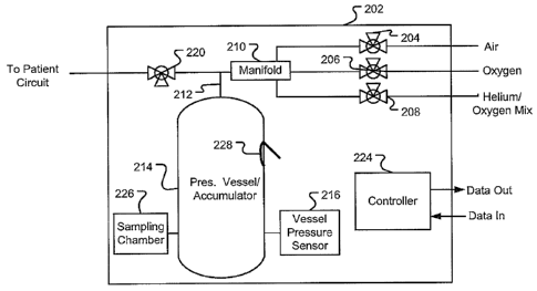
FIGS. 2, 3, and 4 illustrate an embodiment of a pneumatic system 202 (also
referred to as a pressure generating system 202) that reduces air pockets of a
previous
gas mixture in an accumulator from entering the gas flow path. The pneumatic
system
202 includes at least one (four are illustrated) gas regulator 204, 206, 208,
220, a
controller 224, a "T" configuration or T-connector 212, and an accumulator
214, The
pneumatic system 202 may further include a manifold 210 and/or a vessel
pressure
sensor 216. The pneumatic system 202 and/or the controller 224 may be
implemented as
an independent, stand-alone module, e.g., as a separate system either inside
the ventilator
or within a separate housing associated with the ventilator. Alternatively,
the pneumatic
system 202 and/or the controller 224 may be integrated with components of the
CA 02782371 2012-05-30
WO 2011/068771 Attorney Doci_
rCT/US2010/058263
WO
ventilator or another device. In yet another embodiment, the controller 224
may be
implemented independently from the pneumatic system 202.
The pneumatic system 202 receives pressurized gas from a compressor or
centralized pressurized air source, such as wall outlet in a hospital. As
illustrated in
these figures, often times, different gases or gas inixtures have separate
sources or lines.
The concentrations and pressure utilized from a gas source is controlled by a
gas
regulator 204, 206, 208. In the embodiments shown, three different gas sources
are
utilized. One line comprises air and is controlled by gas regulator 204, one
line
comprises oxygen and is controlled by gas regulator 206, and one line
comprises a
helium/oxygen mixture and is controlled by gas regulator 208. In one
embodiment, the
gas regulator 204 can be valve. In the embodiments shown, the gas regulators
are
solenoid valves. Further, in these embodiment, a gas manifold 210 is utilized
to combine
the sources of gas.
A T-connector 212, as illustrated in FIGS. 2, 3, and 4, connects the manifold
210
to a patient circuit and a pressure vessel/accumulator 214. In one embodiment,
as
illustrated in FIGS. 2, 3, and 4, the accumulator is located adjacent to the
flow path and
the manifold in the ventilator system and is not separated from or located
away from the
gas flow path and the manifold. In the "T" configuration 212, the gas flow
path goes
across the top to the "T" and the accumulator 214 is connected to the flow
path by the
stem of the "T". The stem connection of the accumulator 214 removes the
accumulator
214 from the flow path between the manifold 210 and patient circuit. A desired
pressure
range is maintained within the T-connector 212 and between the T-connector
212, the
accumulator 214, and the patient circuit. In one embodiment, the accumulator
214 has a
pressure from 14 pound-force per square inch gauge (PSIG) to 9 PSTG. In a
further
embodiment, the circuit pressure ranges from 5 cm of H20 to 90 cm of H20 for
pneumatic system 202.
The accumulator 214 may be any appropriate size and rated to any appropriate
pressure. In an embodiment, the accumulator 214 has a volume between about
five (5)
milliliters (ml) to about 4 liters. In another embodiment, the accumulator has
a volume
of 500 ml. In yet another embodiment, the accumulator has a volume of 100 ml
to 1000
ml. In a further embodiment, the accumulator 214 volume is between about 400
ml and
about 600 ml. During ventilation of a patient by the ventilator, the pressure
of the
accumulator is held and/or maintained within a desired pressure range. In one
11
CA 02782371 2012-05-30
Attorney Dad V-
T 0
WO 2011/068771 PCT/US2010/058263
embodiment, the desired pressure range is 14 pound-force per square inch gauge
(PSIG)
to 9 PSIG. As utilized herein "ventilation of patient by the ventilator" is
when a
ventilator is delivering a gas mixture to a patient at a required pressure.
In the embodiments shown, the vessel pressure sensor 216 is provided to
monitor
the pressure within the vessel 214. From this information, it can be
determined if the gas
mixture is being stored at the desired pressure. Depending on the embodiment,
the raw
pressure data may be provided to the ventilator, the controller 224, or the
gas regulator
for use in calculating the desired gas flow through the patient circuit. Such
a calculation
can be performed by the controller 224 and/or the ventilator.
In these figures, a gas regulator can be utilized between the manifold 210 and
the
patient circuit and downstream from the stem of the T-connector 212. The
additional gas
regulator 220 can be utilized to adjust any difference found between the
pressure of the
gas mixture and the desired pressure before delivering the gas mixture to the
patient.
In one embodiment, as illustrated in FIG. 2, the stem of the T-connector 212
can
be connected to a dip-tube 218. The dip-tube 218 may be located inside the
accumulator
214 as illustrated in FIGS. 2 and 2A. In another embodiment, the dip-tube 218
is
external to the accumulator 214 as shown in FIG. 2B. The dip-tube 218 extends
the
distance from the flow path and the gas mixture stored in the chamber of the
accumulator
214. This increased distance has been shown in experiments to reduce the
burping effect.
In an alternative embodiment, as illustrated in FIGS. 2C and 2D a purge valve
227 can be added to the accumulator 214 in addition to the dip-tube 218. The
purge
valve 227 can be utilized to expedite the filling of the accumulator 214 with
a new gas
mixture 201. A continued purge will flush out an old gas mixture 203 from the
main
body of the accumulator 214. The purge valve 227 may be located on any part of
the
accumulator 214. In one embodiment, the purge valve 227 is located at the dead-
end of
the accumulator 214 or the end of the accumulator 214 that is opposite or
farthest from
the opening of the dip-tube 218 in order to completely fill the dip-tube
entrance region
with the new gas mixture 201. Once the dip-tube 218, in this configuration, is
filled with
the new gas mixture 201, there is an effective buffer between the new gas
mixture 201
and the old gas mixture 203.
In this embodiment, the purging acts to constantly move the location where the
old gas mixture 203 meets or contacts the new gas mixture 201 (gas mixture
interface
205) down the dip-tube 218 in order to isolate the old gas mixture 203 from
the flow
12
CA 02782371 2012-05-30
Attorney Doc;1110
WO 2011/068771 PCT/US2010/058263
path. As utilized herein, the term "gas interface" refers to the point at
which the old gas
mixture 203 contacts and mixes with the new gas mixture 201. As flow pressure
increases, the gas interface moves farther down the dip-tube 218 toward the
accumulator
214, which increases pressure in the accumulator 214, as illustrated in FIG.
2C. This
increase in pressure may activate the purge valve 227. The active purge 227
may be any
suitable valve for releasing gas mixture from the accumulator 214, such as a
check valve.
Further, the active purge valve 227 may provide safety pressure relief to the
accumulator
214. The activation of the purge valve 227 decreases pressure in the
accumulator 214.
As pressure decreases from activation of the purge valve in accumulator 214,
the gas
interface 205 moves up the dip-tube 218 toward the gas flow path, as
illustrated in FIG.
2D. In one embodiment, the purge flow rate can be chosen based on the time
required to
fill only the dip-tube 218 and, therefore, isolate the old gas mixture 103
from the new gas
mixture 101. Alternatively, the purge flow rate and purging time may be chosen
so that
the old mixture in the accumulator is partially or completely replaced by the
new mixture
In another embodiment, as illustrated in FIG. 3, the accumulator 214 of the
pneumatic system 202 includes an active purge valve 228. The active purge
valve 228
may be similar to or different from the purge valve 227 utilized in dip-tube
embodiment
shown in FIG. 1. The active purge valve 228 may be any suitable valve for
releasing gas
mixture from the accumulator 214, such as a check valve, solenoid valve,
proportional
valve, piloted valve, piston valve, spool valve, diaphragm valve, and poppet
valve. This
list is not limiting. Any suitable valve for purging an accumulator in a
pneumatic system
202 may be utilized with accumulator 214. In one embodiment, pneumatic system
202
utilizes more than one purge valve 228.
Further, the purge valve 228 may provide safety pressure relief to the
accumulator 214. The purge valve 228 allows a stored gas mixture to be purged
from the
accutnulator 214. The active purge valve 228 can be controlled by software
that detects
when the gas mixture is changed. In one embodiment, the controller 224 may
utilize an
active purge module to determine when to purge and/or how much to purge the
gas
mixture stored in the accumulator 214. In another embodiment, the controller
may
control the duration between purges based on the breath size and/or the rate
of
inspiration. In a further embodiment, the controller may control the duration
between
purges based on tidal volume. This module may utilize equations, known
ventilation
relationships, ventilator parameters, sensor readings, and/or commands. This
software
13
CA 02782371 2012-05-30
Attorney Doc ' WO
WO 2011/068771 PCT/US2010/058263
can be stored within the valve, the pneumatic system 202, controller 224, or
somewhere
else within the ventilator system. The software can control the opening of the
purge
valve 228 so the old mixture is replaced by the new mixture over time.
Further, the
active purge valve 228 can be controlled to prevent significant changes in
pressure of the
gas mixture from being delivered to the patient. In one embodiment, the speed
of the gas
mixture replacement is controlled or adjusted based on the delivery of gas
mixture to the
end user. The amount of gas mixture purged can be monitored to determine when
to stop
purging. Accordingly, this embodiment reduces burping of an undesirable gas
mixture
and increases the speed at which the accumulator 214 is filled with the new
mixture of
gas.
In a further embodiment, as illustrated in FIG. 4, the accumulator 214 of the
pneumatic system 202 can be a variable-sized accumulator 214. The variable
size-
accumulator 214 reduces its size, purging a portion of the old gas mixture
when the gas
mixture is changed. The variable sized accumulator 214 can be utilized in any
configuration, such as a "T" configuration 212 or flow through configuration.
Various
designs can be used to implement the variable size-accumulator 214 including a
bellows
design, a multi-chamber design 230 with valves between chambers, and a piston-
based
design.
In one embodiment, a multi-chamber accumulator 214 is utilized, as illustrated
in
FIG-. 4. In this embodiment, a first chamber 230 is separated from a second
chamber
229. The gas flow path between the chambers 229, 230 is connected by a gas
regulator
231 or valve, such as a solenoid valve 231 as illustrated in FIG. 4. The multi-
chambered
accumulator 214 may utilize any suitable number of chambers and/or gas
regulators for
varying the volume of the accumulator to quickly deliver a change in gas
mixture and/or
to reduce or eliminate burps of the old gas mixture from being delivered to
the patient.
The volume of the accumulator 214 ranges from about 10 ml to about 4 liters.
The gas regulator 231 adjusts the volume of the multi-chambered accumulator
214. The volume of the multi-chambered accumulator 214 is changed based on any
suitable ventilator parameters or pressure system parameters, such as a gas
flow rate,
accumulator volume, breath type, and a change in gas mixture concentration.
For
instance, the solenoid valve 231 may only open the first chamber 230 for small
breath
types to allow for fast gas mixture changes. For large breath volumes, the
solenoid valve
14
CA 02782371 2012-05-30
-
WO 2011/068771
Attorney Doc._ rCT/US2010/058263WO
231 may open the gas flow path and allow the first chamber 230 and the second
chamber
229 to work in series to provide the desired volume for these large breath
types.
Further, the pressure of the accumulator 214 can affect the pressure of the
gas
mixture and/or the gas mixture flow rate delivered to a patient from the
ventilator.
Accordingly, the pressure of the ventilator is controlled to maintain a
desired pressure or
a desired pressure range. In one embodiment, the accumulator 214 maintains a
pressure
of the gas mixture in the accumulator 214 within +/- 5 psi during a change in
volume of
the accumulator. In another embodiment, the accumulator 214 maintains a
pressure of
the gas mixture in the accumulator 214 within +/- 3 psi during a change in
volume of the
accumulator. In an additional embodiment, the accumulator 214 maintains a
pressure of
the gas mixture in the accumulator 214 within +/- 1 psi during a change in
volume of the
accumulator.
Purging may be achieved by actively controlled purge valves or check valves
that
purge above a specified relief pressure. The check valve may or may not be the
same
valve that provides safety pressure relief to the accumulator 214. During
purging via
decreasing the volume of the accumulator 214, the control system may use
knowledge of
the volume of the old gas mixture purged and retained to determine by mass
balance the
actual mixture in the accumulator 214 after purging and refilling to the
accumulator's
original volume using the new gas mixture. In one embodiment, the controller
224 may
utilize an accumulator purge module and/or an accumulator gas regulator module
to
determine when to change the accumulator volume and/or when and how much to
purge
the gas mixture stored in the accumulator 214. In another embodiment, the
controller
224 may utilize an accumulator purge module and/or an accumulator gas
regulator
module to determine when to change the accutnulator volume and/or when and how
much to purge the gas mixture stored in the accumulator 214 to maintain a
desired
accumulator pressure. The controller may utilize equations, known ventilation
relationships, ventilator parameters, sensor readings, and/or commands to
determine
when modify the volume of the accumulator 214, when to purge a chamber, and
how to
maintain a desired accumulator pressure.
In another embodiment, the purging/size reduction operation may also be
repeated in order to accelerate the replacement of the old mixture with the
new. In
addition, the purging may be synchronized with the delivery of gas mixture
from the
CA 02782371 2012-05-30
Attorney Doe!
TVO
WO 2011/068771 PCT/US2010/058263
accumulator 214 so that the purging/size changes do not interfere with the
controlled
delivery of respiratory gas to the patient.
In an additional embodiment, as illustrated in FIGS. 2, 3, and 5, a sampling
chamber 226 can be connected to the pressurized vessel/accumulator 214. The
sampling
chamber 226 provides a method for economically determining the concentration
of gases
contained within the accumulator 214. The sampling chatnber 226 may be
utilized on
any type of an accumulator 214, such as the "T" configured accumulators (FIGS.
2 and
3), a variable-sized accumulator, or the flow through accumulators (FIG. 5).
The
sampling chamber 226 periodically, upon conunand, or continuously receives
samples of
the current gas mixture in the accumulator 214. The volume of the sample
and/or the
time duration between samples can be determined based on any suitable
ventilator or
pressure system 202 information, such as a pre-set time interval, an inputted
time-
interval, a command, a sensor reading, a ventilator parameter, a pressure
system
parameter, and a change in a ventilator parameter. The low pressure utilized
in the
sampling chamber 226 allows for the use of less expensive gas concentration
sensors,
such as a Galvanic oxygen sensor.
As discussed above, during ventilation of a patient by the ventilator, the
pressure
of the accumulator 214 is held and/or maintained at a desirable pressure. In
one
embodiment, during ventilation of a patient by the ventilator, the pressure of
the
accumulator 214 is held and/or maintained between about 14 PSIG and about 9
PSIG.
The sampling chamber 226, during ventilation of a patient by the ventilator,
holds and/or
maintains the gas at a pressure that is less titan the pressure maintained in
the
accumulator during ventilation of a patient. For instance, in an embodiment,
the
sampling chamber 226, during ventilation of a patient by the ventilator, holds
and/or
maintains a pressure between about 1 PSIG and about 3 PSIG. In one embodiment,
during ventilation, the pressure of the gas mixture held in the sampling
chamber 226 is
significantly less than the pressure of the gas mixture held in the
accumulator 214 of the
same ventilator system. In another embodiment, during ventilation of a patient
by the
ventilator, the pressure of the gas mixture held in the sampling chamber 226
is at least
75% less than the pressure of the gas mixture held in the accumulator 214 of
the same
ventilator system. In another embodiment, during ventilation of a patient by
the
ventilator, the pressure of the gas mixture held in the sampling chamber 226
is at least
50% less than the pressure of the gas mixture held in the accumulator 214 of
the same
16
CA 02782371 2012-05-30
Attorney Doc i "
WO
WO 2011/068771 PCT/US2010/058263
ventilator system. In a further embodiment, during ventilation of a patient by
the
ventilator, the pressure of the gas mixture held in the sampling chamber 226
is at least
25% less than the pressure of the gas mixture held in the accumulator 214 of
the same
ventilator system.
In one embodiment, .as illustrated in FIG. 5, a gas regulator 232 and a gas
regulator 234 control the amount of sample received by the sampling chamber
226 and
the duration of time that the sample is held within the sampling chamber 226.
In this
embodiment, the gas regulator 232 is a solenoid valve as shown in FIG. 5. In
this
embodhnent, the opening time of the solenoid valve 232 for filling the
sampling chamber
226 depends on the accumulator gas pressure and also on the burst of pressure
of a gas
concentration sensor. In one embodiment, the gas concentration sensor is an
oxygen
sensor. During the filling of the sampling chamber 226, in this embodiment, a
second
gas regulator 234 or valve, such as solenoid exhaust valve remains closed. The
pressure
in the sampling chamber 226 is either maintained at a constant low pressure
suitable for
gas mixture sampling devices or can be controlled so that the pressure can be
reduced to
a pressure suitable for gas mixture sampling devices. Further, the gas
regulator 2328 the
sampling chamber 226, and/or a pressure regulating system allow the
accumulator 214 to
maintain a desired pressure during the taking of a sample. In this embodiment,
both gas
regulators 232 and 234 remain closed during a gas concentration measurement.
Further, in this embodiment, gas regulator 234 opens to release the sample. In
one embodiment, the sample is released into the atmosphere. In one embodiment,
the
gas mixture contained in the sampling chamber 226 is released continuously. In
an
alternative embodiment, the gas mixture contained in the sampling chamber 226
is
released periodically. In another embodiment, the gas mixture contained in the
sampling
chamber 226 is released based on a pre-set or inputted time interval. In one
embodiment,
the gas concentrations of the gas mixture contained in the sampling chamber
226 is
measured during release.
In one embodiment, the measured gas concentration of the sample (or the sensor
output indicative of the measured concentration) is sent the appropriate
ventilator
components, such as a display, a controller 224, a pneumatic system 202, and a
gas
regulator. In another embodiment, a display lists or illustrates the
determined gas
concentration,
17
CA 02782371 2012-05-30
Attorney Don - -
WO
WO 2011/068771 PCT/US2010/058263
Using this approach, the exact mixture within the accumulator 214 can be
directly
determined at any time. The sampling chamber 226 and the flow of accumulator
gas
mixture into and out of the sampling chamber 226, can be controlled by
software,
inputted commands, controller commands, or other ventilator system commands.
Further, the measurements can be communicated to other components, such as the
controller 224, a ventilator display, a ventilator controller 224, the gas
regulator 2043
206, 208, 220, and/or other ventilator components.
In one embodiment, the sampling chamber 226 is positioned as close as possible
to the accumulator 214. In another embodiment, the sampling chamber has a
volume of
about 50 ml or smaller. In yet another embodiment, the sampling chamber has a
volume
of about 30 ml or smaller. In a further embodiment, the sampling chamber has a
volume
of about 20 ml or smaller.
The controller 224 may be identical to the controller 50 described above and
illustrated in FIG. 1 except for being located inside of the pneumatic system
202. It is
understood by a person of skill in the art that the controller 224 can be
located in any
suitable position for receiving senor data, pneumatic system data, inputted
data,
ventilator data, analyzing this data, and issuing commands based on this data.
In FIGS.
2-5, the controller 224 control the gas regulators, the gas mixture changes,
the gas
pressure changes, when to determine the concentrations of the gas mixture in
the
accumulator 214, when to purge an accumulator 214, and/or when to change the
size of a
variable-sized accumulator 214. The controller 224 further receives and
analyzes the
accumulator pressure, the gas mixture concentrations of the accumulator 214,
ventilator
setting, patient readings, inputted parameters, and/or other ventilation
information. In
these embodiments, the controller 224 includes a microprocessor executing
software
stored either on memory within the processor or in a separate memory cache.
The
controller 224 transmits data from the one or more gas regulators, the vessel
pressure
sensor 216, the sampling chamber 226, and/or the active purge valve 228 to
other
devices, such as the ventilator or ventilator display.
The controller 224 may utilize this information to determine gas flow
adjustments, pressure adjustments, purge valve 228 activation, changes in size
for a
variable-sized accumulator 214, and/or gas concentration adjustments. Further,
the
controller 224 may update this information continuously in order to
perform/make the
most accurate determinations. The controller 224 may also receive information
from
18
CA 02782371 2012-05-30
Attorney Doe = "
WO
WO 2011/068771
PCT/US2010/058263
external sources such as modules of the ventilator, in particular, information
concerning
the current breathing phase of the patient, ventilator parameters, and/or
other ventilator
readings. The information received may include user-selected or predetermined
values
for various parameters such as accumulator pressure, between-discharges delay
period,
and sensor estimate interval, etc. The information received may further
include
directions, such as a ventilator-generated gas mixture concentration command,
purge
valve 228 activation command, size change command for a variable-sized
accumulator
214, and/or an operator command to change the gas mixture or pressure (e.g.,
an
automatic or a manual command). The controller 224 may also include an
internal timer
so that specific readings, such as vessel pressure sensor 216 readings and
vessel gas
concentration readings and commands can be performed at a user or manufacturer
specified interval.
FIG. 6 represents an embodiment of a method for ventilating a patient, 600.
As illustrated, method 600 provides a dip-tube, 602. The dip-tube has a first
end
within an accumulator positioned away from a flow path and a second end
connected to
the flow path. The distance between the first end and the second end is a
length selected
to reduce undesirable pockets of a gas mixture contained in the accumulator
from
entering the flow path to a patient circuit. The diameter of the dip-tube is
selected to
prevent and/or reduces undesirable pockets of a gas mixture contained in the
accumulator
from entering the gas flow path. In one embodiment, the accumulator is
adjacent to a
gas manifold and the gas flow path. In another embodiment, the dip-tube is
substantially
located within the accumulator.
Method 600 further controls a flow rate of the first gas mixture to keep a gas
interface inside the dip-tube 604. The gas interface is the location where a
gas mixture
contained in the accumulator meets or contacts a changed gas mixture found in
the flow
path. By keeping the gas interface inside the dip-tube, an effective buffer is
created
between the gas mixture contained in the accumulator and the changed gas
mixture
found in the flow path. This buffer prevents and/or reduces undesirable
pockets of the
gas mixture contained in the accumulator from entering the gas flow path.
In one embodiment, method 600 measures the gas pressure of the accumulator
and then purges the gas mixture contained in the accumulator based on the
measured gas
pressure and the controlled gas flow rate. The gas pressure of the accumulator
can be
measured utilizing a pressure sensor connected to the accumulator. An
accumulator
19
CA 02782371 2012-05-30
WO 2011/068771
Attorney DocpCTIUS2010/058263- WO
purge valve may be utilized to purge the accumulator. The purge valve may be
any
suitable valve for releasing gas mixture from the accumulator, such as a check
valve.
Further, the purge valve may provide safety pressure relief to the
accumulator. The
activation of the purge valve decreases pressure in the accumulator. As
pressure
decreases from the activation of the purge valve in accumulator, the gas
interface moves
up the clip-tube toward the gas flow path. The purge valve and/or a controller
are
adapted to gradually replace the gas mixture contained in the accumulator with
the
changed gas mixture found in the flow path. In one embodiment, the controller
may
utilize the measured pressure of the accumulator to control the accumulator
purge valve
and effect the location of the gas interface.
FIG. 7 represents an embodiment of a method for ventilating a patient, 700. As
illustrated, method 700 changes a gas mixture in a flow path of a medical
ventilator, 702.
The gas mixture can be changed by receiving different amounts of a gas from a
plurality
of sources of different gases. In one embodiment, the sources of the different
gases are
controlled by a controller or a processor. The change in gas mixture can be in
response
to at least one of received patient information, ventilation information, and
inputted
commands.
Further, method 700 measures a gas flow rate of the gas mixture in the flow
path
of the medical ventilator, 704. A proximal flow sensor may be utilized to
measure the
gas mixture flow rate. In one embodiment, the proximal flow sensor is
controlled by a
controller or processor. Any suitable sensor for measuring gas mixture flow
rate in the
flow path of the ventilator can be utilized in the ventilator. Further, the
flow rate sensor
can be utilized in any suitable location in the flow path for obtaining a
substantially
accurate reading of the gas mixture flow rate.
Method 700 controls an active gas purge valve in an accumulator positioned
away from the flow path based on at least one of the measured gas flow rate
and the
changed gas mixture concentration, 706. The active purge valve may be any
suitable
valve for releasing gas mixture from the accumulator, such as a check valve.
Further, the
purge valve may provide safety pressure relief to the accumulator.
The active purge valve can be activated to gradually replace a gas mixture
contained in the accumulator with a changed gas mixture. In one embodhnent, a
controller or a processor may analyze at least one of the measured gas flow
rate and the
changed gas mixture concentration to determine how to control the active gas
purge
CA 02782371 2012-05-30
Attorney Doel WO
WO 2011/068771 PCT/US2010/058263
valve. In one etnbodiment, method 700 purges a gas mixture contained in the
accumulator based on the measured gas flow rate and the changed gas mixture
concentration. In a further embodiment, method 700 stops the purge of the gas
mixture
contained in the accumulator based on the measured gas flow rate and the
changed gas
mixture concentration. In another embodiment, method 700 controls a duration
between
purges based on a breath size and/or a rate of inspiration. In a further
embodiment,
method 700 controls a duration between purges based tidal volume.
In another embodiment, method 700 measures a pressure of a gas mixture in the
accumulator and controls the active gas purge valve based on the measured
pressure.
Activating and deactivating the gas purge valve affects the pressure of the
accumulator.
The pressure of the accumulator can affect the pressure of the gas mixture
and/or the gas
mixture flow rate delivered to a patient from the ventilator. Accordingly, the
pressure of
the ventilator is controlled to maintain a desired pressure. In a further
embodiment,
method 700 controls the purging of the accumulator based on the measured
pressure. In
another embodiment, method 700 displays at least one of a gas flow rate, a gas
mixture
concentration, and a purge valve activation.
FIG. 8 represents an embodiment of a method for ventilating a patient, As
illustrated, method 800 controls when a sample of a gas mixture is received by
a
sampling chamber from an accumulator, 802. In one embodiment, a gas regulator
controls when a sample is taken from the accutnulator. The gas regulator may
be any
suitable valve for connecting the accumulator and the sampling chamber in a
ventilator,
such as check valve or solenoid valve. Further, method 800 controls a volume
of the
sample received by the sampling chamber from the accumulator, 804. In an
embodiment, a gas regulator controls the volume of the sample take from the
accumulator. In another embodiment, a processor may control the gas regulator.
Additionally, method 800 controls a pressure of the sample in the sampling
chamber, 806. The pressure of the sample in the sampling chamber is less than
a pressure of the gas mixture in the accumulator during ventilation of a
patient at the
same time. In one embodiment, the step of controlling a pressure of the sample
in the
sampling chamber, 806, includes maintaining a desirable gas mixture pressure
range
during ventilation of a patient. In another embodiment, the accumulator
maintains the
pressure of the gas mixture from about 14 PSIG to about 9 PSIG during
ventilation of the
patient. In a further embodiment, the step of controlling a pressure of the
sample in the
21
CA 02782371 2012-05-30
Attorney Doe) OV
WO 2011/068771 PCT/US2010/058263
sampling chamber, 806, includes maintaining the pressure of the sample at a
pressure of
at least 75% less than the pressure of the gas mixture maintained in the
accumulator at
the same time during ventilation of a patient.
In an embodiment, method 800 further controls the release of the sample from
the
sampling chamber. In one embodiment, an exhaust valve controls when a sample
is
released from the sampling chamber. The exhaust valve may be any suitable
valve for
releasing the satnple from the sampling chamber in a ventilator, such as check
valve or
solenoid valve. In a further embodiment, a processor controls the exhaust
valve. In one
embodiment, the activation of the gas regulator and the exhaust valve affect
the timing,
volume, and pressure of the sample taken fiom the accumulator.
In another embodiment, the step of controlling when the sample of the gas
mixture is received by the sampling chamber from the accumulator 802, the step
of
controlling the volume of the sample received by the sampling chamber from the
accumulator 804, and the step of controlling the pressure of the sample in the
sampling
chamber 806 are controlled based on at least one of a sensor reading, a change
in a gas
mixture, a ventilator parameter, and a command. In a further embodiment, a
processor
may be utilized control steps 802, 804, and 806.
Method 800 measures a gas mixture concentration of the sample received by the
sampling chamber, 808. The gas mixture concentration can be measured by a
sensor in
the sampling device. In one embodiment, the step of measuring the gas mixture
concentration of the sample received by the sampling chamber, 808, includes
measuring
the gas mixture concentration of the sample during storage of the sample in
the sampling
chamber. In an alternative embodiment, the step of measuring the gas mixture
concentration of the sample received by the sampling chamber, 808, includes
measuring
the gas mixture concentration of the sample as the sample flows through the
exhaust
valve. The measured gas mixture concentration of the sample may be
communicated to
another ventilator component. In one embodiment, the measured gas mixture
concentration of the sample is displayed.
FIG. 9 represents an emboditnent of a method for ventilating a patient. As
illustrated, method 900 controls a change in gas mixture, 902. The gas mixture
can be
changed by receiving different amounts of a gas from a plurality of sources of
different
gases. In one embodiment, the sources of the different gases ate controlled by
a
controller or a processor. The gas mixture may be changed by a gas regulator.
The gas
22
CA 02782371 2012-05-30
Attorney Doer -- -- - - - - ¨ ¨ - WO
WO 2011/068771
PCT/US2010/058263
regulator may control the amount of a pure gas taken into the ventilator. The
gas mixture
may be changed based on user command, pre-set requirements, patient
information, and
other ventilator information.
As illustrated, method 900 measures a gas flow rate in a patient circuit, 904.
A
proximal flow sensor may be utilized to measure the gas mixture flow rate, The
proximal flow sensor may be controlled by a controller or processor. Any
suitable
sensor for measuring gas mixture flow rate in the flow path of the ventilator
can be
utilized in the ventilator. Further, the flow rate sensor can be utilized in
any suitable
location in the flow path for obtaining a substantially accurate reading of
the gas mixture
flow rate.
Further, method 900 measures a pressure of an accumulator with a plurality of
chambers, 906. The pressure of the accumulator may be measure by a pressure
sensor.
In one embodiment, the plurality of chambers includes two chambers. In an
alternative
embodiment, the plurality of chambers includes three or more chambers.
Method 900 controls the volume of the accumulator by controlling at least one
gas regulator, the at least one gas regulator controlling at least one gas
flow connection
between the plurality of chambers, 908. The volume of the accumulator can
range from
about 10 ml to about 4 liters depending upon how many chambers of the
plurality of
chambers have an open or at least partially open flow path connection. The at
least one
gas regulator can be any suitable valve for connecting chambers in an
accumulator, such
as a solenoid valve. The volume of the accumulator is increased by activating
the at least
one gas regulator to open or at least partially open at least one chamber flow
path
between chambers. The volume of the accumulator is reduced by activating the
at least
one gas regulator to close the chamber flow path between at least one chamber.
Accordingly, the step of controlling the volume of the accumulator, 908,
includes
changing the volume of the accumulator. In one embodiment, the volume of the
accumulator ranges from about 100 ml to about 100 ml depending upon how many
chambers of the plurality of chambers have an open or at least partially open
flow path
connection. In one embodiment, the volume of the accumulator has a maximum
volume
of about 500 ml.
Additionally, method 900 controls a release of a gas mixture from each chamber
of the accumulator to an environment external to the patient circuit by
controlling a
plurality of purge valves in each chamber of the accumulator, 910. The
plurality of
23
CA 02782371 2012-05-30
Attorney DM- TO
WO 2011/068771 PCT/US2010/058263
purge valves may be any suitable valves for releasing gas mixture from the
accumulator,
such as check valves. Further, the plurality of purge valves may provide
safety pressure
relief to each chamber of the accumulator. The purge valves allow for the gas
mixture
contained in each chamber of the accumulator to be gradually replaced with a
new or
changed gas mixture.
Accordingly, method 900 controls the pressure of the accumulator by
controlling
the plurality of purge valves and the at least one gas regulator, 912. The
pressure and the
volume of the accumulator are controlled based on at least one of the change
in gas
mixture, the measured gas flow rate, and the measured pressure of the
accumulator
during ventilation of a patient. In another embodhnent, the step of
controlling the
pressure of the accumulator, 912, includes activating at least one of the
plurality of purge
valves. The activation of a purge valve can decrease the pressure of a chamber
and/or
the accumulator. Further, the closing of at least one of the plurality purge
valves can
increase the pressure of a chamber and/or the accumulator. Additionally, the
closing of a
gas regulator can increase the pressure in at least one chamber of the
accumulator that is
still receiving gas mixture from the flow path. In one embodiment, the step of
controlling the pressure of the accumulator 912 includes maintaining the
pressure of the
gas mixture in the accumulator within about +/- 5 psi to +/- 1 psi during a
change in
volume of the accumulator. The pressure of the accumulator can affect the
pressure
and/or the flow rate of the gas mixture delivered to a patient from the
ventilator.
Accordingly, the pressure of the ventilator is controlled to maintain a
desired pressure.
In one embodiment, method 900 controls a breath type. Accordingly, in this
embodiment, the pressure and the volume of the accumulator are controlled
based on the
at least one of the change in gas mixture, the measured gas flow rate, and the
measured
pressure of the accumulator and the controlled breath type. In another
embodiment,
method 900 displays at least one of the volume and the pressure of the
accumulator. In a
further embodiment, method 900 communicates at least one of the volume and the
pressure of the accumulator to another ventilator component.
Numerous other changes may be made which will readily suggest themselves to
those skilled in the art and which are encompassed in the spirit of the
disclosure and as
defined in the appended claims. While various embodiments have been described
for
purposes of this disclosure, various changes and modifications may be made
which are
well within the scope of the present invention. Numerous other changes may be
made
24
CA 02782371 2014-01-16
which will readily suggest themselves to those skilled in the art and which
are encompassed
in and defined in the appended claims.
Unless otherwise indicated, all numbers expressing quantities, properties,
reaction
conditions, and so forth used in the specification and claims are to be
understood as being
modified in all instances by the term "about." Accordingly, unless indicated
to the contrary,
the numerical parameters set forth in the following specification and attached
claims are
approximations that may vary depending upon the desired properties sought to
be obtained
by the present invention.
As used herein, "about" refers to a degree of deviation based on experimental
error
typical for the particular property identified. The latitude provided the term
"about" will
depend on the specific context and particular property and can be readily
discerned by those
skilled in the art. The tern "about" is not intended to either expand or limit
the degree of
equivalents which may otherwise be afforded a particular value. Further,
unless otherwise
stated, the term "about" shall expressly include "exactly," consistent with
the discussions
regarding ranges and numerical data. Concentrations, amounts, and other
numerical data
may be expressed or presented herein in a range format. It is to be understood
that such a
range format is used merely for convenience and brevity and thus should be
interpreted
flexibly to include not only the numerical values explicitly recited as the
limits of the range,
but also to include all the individual numerical values or sub-ranges
encompassed within
that range as if each numerical value and sub-range is explicitly recited. As
an illustration, a
numerical range of "about 4 percent to about 7 percent" should be interpreted
to include not
only the explicitly recited values of about 4 percent to about 7 percent, but
also include
individual values and sub-ranges within the indicated range. Thus, included in
this
numerical range are individual values such as 4.5, 5.25 and 6 and sub-ranges
such as from 4-
5, from 5-7, and from 5.5-6.5; etc. This same principle applies to ranges
reciting only one
numerical value. Furthermore, such an interpretation should apply regardless
of the breadth
of the range or the characteristics being described.