Note: Descriptions are shown in the official language in which they were submitted.
CA 02782412 2014-11-13
INTERACTIVE MULTILEVEL ALARM
Introduction
A ventilator is a device that mechanically helps patients breathe by replacing
some
or all of the muscular effort required to inflate and deflate the lungs.
Ventilators also
achieve a regulatory function during the ventilation process. A ventilator
measures
numerous physiological and operational parameters, including but not limited
to exotic gas
utilization, peak inspiratory pressure, battery failure and filter
replacement. Depending on
the status of the different parameters, it may be necessary for the ventilator
to generate an
alarm to indicate to the operator that attention is required.
Apparatus for an Interactive Multilevel Alarm
This disclosure describes embodiments of alarm systems and methods for use in
devices such as medical ventilators. Embodiments described below provide for
an apparatus
of an interactive multilevel alarm system. Embodiments of the alarms also
provide, at a
glance, current alarm and device status information and historical alarm
information to the
operator. Embodiments also detect interaction with the alarm indicator by the
operator. In
some embodiments, additional visual indicators may be provided to identify non-
normal or
noteworthy operating conditions, such as the use of a therapeutic gas by a
mechanical
ventilator, so that the operator can assess the impact of that non-normal
condition on the
current and historical alarm information simultaneously provided.
In one aspect, this disclosure describes a method for interacting with an
alarm system
when the alarm system is in an alarm state, the method comprising: providing a
first and
second interactive indicator, the first and second interactive indicators
visible in a 360
degree arc when viewed from a predetermined height; generating an alarm
indication
associated with the alarm state via the first interactive indicator, wherein
the alarm
indication includes lighting the first interactive indicator; detecting an
operator's input at
one of the first and second interactive indicators, wherein the operator's
input is a direct
interaction at one of the first and second interactive indicators; determining
a type of input
corresponding to the operator's input; and modifying the alarm indication
based on the
1
CA 02782412 2014-11-13
determined type of input and the interactive indicator at which the operator's
input was
detected.
The disclosure also describes a ventilation system including an alarm system
adapted
to provide respiratory therapy to a patient when the alarm system is in an
alarm state, the
ventilation system comprising: a first and second interactive indicator, the
first and second
interactive indicators visible in a 360 degree arc when viewed from a
predetermined height;
a processor communicably coupled to a computer readable medium, wherein the
computer
readable medium includes instructions executable by the processor to: generate
an alarm
indication associated with the alarm state via the first interactive
indicator, wherein the
alarm indication includes lighting the first interactive indicator; detect an
operator's input at
one of the first and second interactive indicators, wherein the operator's
input is a direct
interaction at one of the first and second interactive indicators; determine a
type of input
corresponding to the operator's input; and modify the alarm indication based
on the
determined type of input and the interactive indicator at which the operator's
input was
detected.
The disclosure also describes an interactive alarm indication system for use
on a
ventilator comprising: at least one of interactive indicators, each
interactive indicator
comprising an interactive element, the at least one interactive indicator
visible in a 360
degree arc around the interactive alarm indication system when viewed from a
predetermined height, the at least one interactive indicator including: a
current status
indicator adapted to display one of a different color and a different
combination of color and
behavior based on a current status of the ventilator; a secondary indicator
adapted to display
one of a different color and a different combination of color and behavior
based on a highest
historical status of the ventilator; wherein the current status indicator and
the secondary
indicator are further configured to: identify an alarm condition; generate an
alarm indication
associated with the alarm condition at the at least one interactive indicator;
detect an
operator's input at the interactive element, wherein the operator's input is a
direct interaction
at one of the current and secondary indicators; compare the operator's input
to a plurality of
input types; determine a type of input corresponding to the operator's input;
and
modify the alarm indication based on the determined type of input.
2
CA 02782412 2014-11-13
These and various other features as well as advantages will be apparent from a
reading of the following detailed description and a review of the associated
drawings.
Additional features are set forth in the description that follows and, in
part, will be apparent
from the description, or may be learned by practice of the described
embodiments. The
benefits and features will be realized and attained by the structure
particularly pointed out in
the written description and claims hereof as well as the appended drawings.
It is to be understood that both the foregoing general description and the
following
detailed description are exemplary and explanatory and are intended to provide
further
explanation of the claimed invention.
2a
CA 02782412 2012-05-30
WO 2011/069044 PCT/US2010/058854
Brief Description of the Drawings
The following drawing figures, which form a part of this application, are
illustrative of described technology and are not meant to limit the scope of
the invention
as claimed in any manner, which scope shall be based on the claims appended
hereto.
FIG. 1 depicts a ventilator used during mechanical ventilation of a patient.
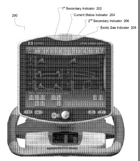
FIGS. 2-6 provide different views of a ventilator having a display and built
into the top of the display housing a four indicator visual alarm system
comprising a
lower, exotic gas indicator, a first and a second secondary indicator and a
current
status indicator.
FIG, 2 is a front view of the display showing the four indicators.
FIG. 3 is an oblique front view of the display showing the four indicators.
FIG. 4 is a side view of the display showing the four indicators.
FIG. 5 is an oblique rear view of the display showing the four indicators.
FIG. 6 is a rear view of the display showing the four indicators.
FIG. 7 depicts different ventilation urgency levels communicated by
different colors of light or combinations of light and behavior displayed by
the
indicators. The illustrations are top views of only the current status and
secondary
indicators showing the different color schemes for an embodiment of operation.
One side view is also shown.
FIG, 8 depicts different visual combinations of the different indicators of
the
interactive multilevel alarm system from a top view.
FIG. 9 depicts a method of escalation or de-escalation in current indicator
status.
FIG. 10 depicts a method of indicating a highest historical ventilator system
status at a secondary indicator.
FIG. 11 depicts a method for providing interactivity with the multilevel
alarm system of the ventilator by making one or more of the indicators an
interactive
element.
3
CA 02782412 2012-05-30
WO 2011/069044 PCT/US2010/058854
Detailed Description
Although the techniques introduced above and discussed in detail below may be
implemented for a variety of devices, the present disclosure will discuss the
implementation of these techniques for use in a mechanical ventilator system
for use in
providing ventilation support to a human patient. The reader will understand
that the
technology described in the context of a medical ventilator for human patients
could be
adapted for use with other systems such as ventilators for non-human patients,
different
types of medical devices and any devices that can generate multiple alarms or
operate in
one or more of multiple different states.
Medical ventilators monitor the delivery of breathing gas to the patient, may
directly or indirectly monitor physiological parameters of the patient, and
monitor the
operation of the ventilator. For the purposes of this discussion, the
ventilator will be
referred to as including an interactive multilevel alarm system as a way of
collectively
talking about those elements in the control systems of the ventilator that
generate alarms
based on the various parameters monitored by the ventilator. The interactive
multilevel
alarm system includes a visible alarm display system and may include an
audible alarm
generating system. The visible alarm display system refers to those components
(e.g.
visible indicators) other than the graphical user interface of the ventilator
that provide
visible indications of alarms and ventilator status information to the
operator. Likewise,
the audible alarm system refers to those components (e.g. speakers and sound
generators) responsible for generating audible alarms.
The interactive multilevel alarm system indicates the current status level of
the
ventilator at a current status indicator. The current status indicator may be
located on
the ventilator such that the operator may be able to see the current status
indicator from
any side or angle. Depending on the settings provided, selected therapy and
other
conditions, a ventilator may be designed to generate some number of alarms of
different
magnitudes based on the current status level. Alarms of different magnitudes
may be
grouped into arbitrary "levels" dictated by the urgency or level of response
deemed
necessary by operators or by some characteristic. For example, in the
embodiments
described in this disclosure, at any given time while providing therapy to a
patient a
ventilator may be in one of four different current conditions.
= A "no current alarm" or normal operation status level;
= A low-level alarm condition;
4
CA 02782412 2012-05-30
WO 2011/069044
PCT/US2010/058854
= A medium-level alarm condition;
= A high-level alarm condition.
Different current status levels displayed at the current status indicator
indicate
to the operator that a different response is needed and different visual and
audible alarms
may be associated with each status level. For example, a low-level alarm may
require
no immediate attention but is provided for informational purposes only. A
medium-
level alarm may indicate that the operator should evaluate the conditions that
caused the
alarm in order to determine if an action is necessary. A high-level alarm
condition may
indicate a life-threatening or other emergency that requires immediate
attention.
For example, a low-level alarm may be generated when a measured parameter,
such as peak inspiratory pressure observed in a patient during breathing,
exceeds a
threshold amount (an example of patient physiological parameter being outside
the
targeted range); when a battery has failed, a condensate collection cup is
full or a filter
needs replacing (an example of an alarm being generated based on an
operational
condition.) Similarly, the low level alarm may be "escalated" to a medium
level alarm if
the measured parameter is observed to be in excess of the threshold for a
predetermined
period of time. If the patient's total exhaled tidal volume was to drop below
the set
point or the ventilator determines that the patient has become disconnected
from the
ventilator, a high-level alarm may be initiated. Escalation will be discussed
further
herein.
FIG. 1 illustrates an embodiment of a ventilator 100 connected to a human
patient 150. Ventilator 100 includes a pneumatic system 102 (also referred to
as a
pressure generating system 102) for circulating breathing gases to and from
patient 150
via the ventilation tubing system 130, which couples the patient to the
pneumatic system
via an invasive patient interface 152.
Ventilation may be achieved by invasive or non-invasive means. Invasive
ventilation, such as invasive patient interface 152, utilizes a breathing
tube, particularly
an endotracheal tube (ET tube) or a tracheostomy tube (trach tube), inserted
into the
patient's trachea in order to deliver air to the lungs. Non-invasive
ventilation may utilize
a mask or other device placed over the patient's nose and mouth. For the
purposes of
this disclosure, an invasive patient interface 152 is shown and described,
although the
reader will understand that the technology described herein is equally
applicable to any
invasive or non-invasive patient interface.
5
CA 02782412 2012-05-30
WO 2011/069044 PCT/US2010/058854
Airflow is provided via ventilation tubing circuit 130 and invasive patient
interface 152. Ventilation tubing circuit 130 may be a dual-limb (shown) or a
single-
limb circuit for carrying gas to and from the patient 150. In a dual-limb
embodiment as
shown, a "wye fitting" 170 may be provided to couple the patient interface 154
to an
inspiratory limb 132 and an expiratory limb 134 of the ventilation tubing
circuit 130.
Pneumatic system 102 may be configured in a variety of ways, In the present
example, system 102 includes an expiratory module 110 coupled with the
expiratory
limb 134 and an inspiratory module 104 coupled with the inspiratory limb 132.
Compressor 106 or another source(s) of pressurized gases (e.g., air, oxygen,
and/or
helium) is coupled with inspiratory module 104 to provide a gas source for
ventilatory
support via inspiratory limb 132.
The pneumatic system may include a variety of other components, including
sources for pressurized air and/or oxygen, mixing modules, valves, sensors,
tubing,
accumulators, filters, etc. Controller 112 is operatively coupled with
pneumatic system
102, signal measurement and acquisition systems, and an operator interface 120
may be
provided to enable an operator to interact with the ventilator 100 (e.g.,
change ventilator
settings, select operational modes, view monitored parameters, etc.).
Controller 110
may include memory 114, one or more processors 118, storage 116, and/or other
components of the type commonly found in command and control computing
devices.
The memory 112 is computer-readable storage media that stores software that
is executed by the processor 116 and which controls the operation of the
ventilator 100.
In an embodiment, the memory 112 includes one or more solid-state storage
devices
such as flash memory chips. In an alternative embodiment, the memory 112 may
be
mass storage connected to the processor 116 through a mass storage controller
(not
shown) and a communications bus (not shown). Although the description of
computer-
readable media contained herein refers to a solid-state storage, it should be
appreciated
by those skilled in the art that computer-readable storage media can be any
available
media that can be accessed by the processor 116. Computer-readable storage
media
includes volatile and non-volatile, removable and non-removable media
implemented in
any method or technology for storage of information such as computer-readable
instructions, data structures, program modules or other data. Computer-
readable storage
media includes, but is not limited to, RAM, ROM, EPROM, EEPROM, flash memory
or
other solid state memory technology, CD-ROM, DVD, or other optical storage,
magnetic cassettes, magnetic tape, magnetic disk storage or other magnetic
storage
6
CA 02782412 2012-05-30
WO 2011/069044 PCT/US2010/058854
devices, or any other medium which can be used to store the desired
information and
which can be accessed by the computer.
The controller 110 issues commands to pneumatic system 102 in order to
control the breathing assistance provided to the patient by the ventilator.
The specific
commands may be based on inputs received from patient 150, pneumatic system
102
and sensors, operator interface 118 and/or other components of the ventilator.
In the
depicted example, operator interface includes a display 120 that is touch-
sensitive,
enabling the display to serve both as an input and output device.
As depicted, the alarm system 122 is communicatively connected to the
controller 110. The controller 110 of the ventilator can direct the alarm
system 122 to
generate alarms under predetermined circumstances. Different predetermined
circumstances can cause the controller 110 to communicate different alarm
levels to the
alarm system 122. The different alarm levels communicated by the controller
110 cause
the alarm system 122 to display different alarm statuses on alarm system
indicators as
described herein. The controller 110 also communicates to the alarm system 122
whether the ventilator is delivering an exotic gas to the patient. Delivery of
an exotic
gas is also displayed by the alarm system 1122 on an alarm system indicator as
described
herein.
The alarm system 122 is also communicatively connected, either directly or
indirectly, to the display 120. When the alarm system 122 detects an
operator's input,
the alarm system 122 causes the display 120 to display alarm conditions.
FIG. 2 illustrates an embodiment of a visible alarm display system 200. The
visual alarm display system 200 includes alarm lights, referred to herein as
indicators.
The visible alarm display system includes a current status indicator 204, a
secondary
indicator, in this embodiment made up of a first secondary indicator 202 and a
second
secondary indicator 206, and an exotic gas indicator 208. The indicators may
include
one or more of any type including incandescent lights, light emitting diodes
(LEDs), or
other technology capable of creating visually perceptible light.
The general operation of the current status indicator 204 has already been
discussed. The secondary indicator, which in the emboditnent shown consists of
two
non-contiguous zones 202 and 206, indicates the highest historical alarm
level. The
highest historical alarm level reflects the highest current status level
reached since the
alarm was last reset. Thus, an operator viewing the secondary indicator 202
and 206
will instantly know if the ventilator has in the past been in an alarm state
regardless of its
7
CA 02782412 2012-05-30
WO 2011/069044 PCT/US2010/058854
current status. Depending on the embodiment, the secondary indicator 202 and
206 may
indicate only the existence of a historical alarm state higher than the
current status of the
ventilator. In other words, the secondary indicator 202 and 206 will display
the current
status level if the current status level is equal to or higher than the
highest historical
status level. The secondary indicator 202 and 206 may also be referred to as a
"latched
indicator" to allude to its function as latching to the highest alarm level
seen by the
ventilator since the last time the alarm system was reset by the operator or
the ventilator
was powered up.
The secondary indicator 202 and 206 in the illustrated embodiment highlights
that in the three indicator alarm described herein, any of the indicators
(i.e., the current
status indicator, the secondary alarm indicator and the exotic gas indicator)
may consist
of separate individual indicators or zones that act together so that at least
one zone of
each indicator is visible from all angles. When discussing embodiments in
which an
indicator (i.e., the current status indicator, the secondary alarm indicator
and the exotic
gas indicator) has multiple, non-contiguous zones, the different zones will be
referred to
as a "first" indicator and "second" indicator of that particular type (e.g.,
the first current
status indicator and second cunent status indicator), although the reader will
understand
that the first and second indicators may also be referred to collective as a
single indicator
(e.g., the current status indicator may consist of a first and second current
status
indicator).
In the embodiment shown, for instance, the visual display system includes a
first secondary indicator 202 and a second secondary indicator zone 206. The
first
secondary indicator 202 and the second secondary indicator 206 flank either
side of
the current status indicator 204. In an embodiment, the current status
indicator 204
and secondary indicator 202 and 206 are located on the ventilator such that,
when
viewed from predetermined heights such as heights above 4 feet above the floor
on
which the ventilator is standing, at least one secondary indicator is visible
from any
direction in a 360 degree arc around the ventilator. That is, regardless of
the relative
angle of the operator to the ventilator (e.g., facing the ventilator from the
front, back,
sides, etc.) at least one of the two secondary indicators will be in view.
In the embodiments shown herein, this is achieved by placing the indicators,
with the current status indicator 204 above and the secondary indicator below
202
and 206, on top of the highest point of the ventilator. Other configurations
are also
possible including providing multiple indicators at multiple locations around
the
8
CA 02782412 2012-05-30
WO 2011/069044
PCT/US2010/058854
housing of the ventilator or providing indicators in the form of bands running
around
the exterior of the ventilator at different heights.
In one embodiment, the current status indicator 204 and the secondary
indicators 202 and 206 are touch sensitive. Detection of an operator's touch
to
either indicator is considered acknowledgement by a user to address the alarm
condition. In an embodiment, such an acknowledgement may cause the alarm
system to lower the volume, display specific windows or information on the
display
or cease the emission of an audible alarm associated with the current
ventilator
status level.
The interactive element may be able to differentiate between different types
of inputs from the operator, such as differentiating between a tap, a touch
starting
from the left and going to the right and a touch starting from the right and
going to
the left. Depending on what type of input is received, the audible alarm may
be
modified in different ways. For example, a tap may silence the alarm, a longer
touch may pull up a particular window on the display related to the alarm and
a left-
to-riglit or right-to-left touch may make the alarm louder or quieter.
Different interactive elements may be provided for the audible alarm control
and for the visual alarm control. For example, touching the current status
indicator
204 may control the audible alarm and touching the secondary indicator 202 and
206
may clear the historical status level so that the historical status level is
reset to the
current status level. In yet another embodiment, the operator could bring up a
control panel/cause the ventilator to display a graphical user interface
associated
with the alarm condition by touching the current status indicator 204 or
secondary
indicator 202 and 206.
The interactive element may use any suitable technology or device in order
to detect the operator command. For example, in an embodiment an indicator may
incorporate a mechanical push switch so that the indicator can be depressed by
the
operator's finger. Alternatively, a touch-sensitive technology such as
resistive,
capacitive, acoustic pulse recognition or any other technology, now known or
later
developed, for detecting a user input. In an embodiment the entire display
housing
including the visual indicators could be covered by a material, such as a
glass or
polymer to create a unitary, smooth exterior surface into which different
interactive
elements are located in different areas of the cover material. Thus, different
areas of
9
CA 02782412 2012-05-30
WO 2011/069044 PCT/US2010/058854
the housing surface including the surface of the visual indicators could be
used as
interface elements.
In yet another embodiment, additional interactive elements may be provided
at various locations on the ventilator for interacting with the alarm system
and
controlling the audio and visual alarms. For example, when an audible alarm is
active an interactive element for controlling volume may appear or be
illuminated so
that the operator is alerted to the location of the element. As another
example, the
current status indicator 204 could be one interactive element that silences
the audible
alarm and another interactive element could be located somewhere else on the
ventilator to control the volume of the audible alarm, such as on the main
ventilator
display.
The visible alarm display system may also include an exotic gas indicator 208.
In an embodiment, the exotic gas indicator 208 can be viewed from any position
around
the ventilator. For example, in one embodiment, each of the three indicators
(current
status, secondary and exotic gas) are stacked, one on top of the other, and
placed on top
of the highest component of the ventilator. The exotic gas indicator 208 may
be off until
such time as an exotic gas is in use. In an embodiment, the exotic gas
indicator 208 may
use a different color or color/behavior combination for each different exotic
gas so that
the operators know which gas is in use. Alternatively, a single color may be
used in
which the gas in use cannot be determined from the indicator. Likewise, the
exotic gas
indicator 208 may be adapted to also indicate specific ranges of oxygen
concentrations,
for example lighting when a gas mix setting such as oxygen drops below or
exceeds an
operator set limit. Such an indication could be used to note a change in the
patient's
status. In another embodiment, the exotic gas indicator can display different
colors to
indicate different exotic gasses used during ventilation.
An interactive element may also be incorporated into the exotic gas indicator
208. In an embodiment, for example, an operator could disable the delivery of
the
exotic gas by touching the exotic gas indicator 208. Alternatively, the
operator could
bring up a control panel/cause the ventilator to display a graphical user
interface
associated with and/or controlling the exotic gas delivery by touching the
exotic gas
indicator 208. Such an interactive element may or may not be disabled when
there is no
exotic gas being delivered.
CA 02782412 2012-05-30
WO 2011/069044 PCT/US2010/058854
FIG. 3 depicts the visual alarm display system 300 from an oblique view. As
can
be seen, the current status indicator 304, first secondary indicatory 302,
second
secondary indicator 306, and exotic gas indicator 308 are all visible from the
side angle.
FIG. 4 depicts the visual alarm display system 4E10 from a side view. As can
be
seen, the current status indicator 402, second secondary indicator 404, and
exotic gas
indicator 406 are all visible from the side.
FIG. 5 depicts the visual alarm display system 500 from an oblique rear view.
As can be seen, the current status indicator 504, first secondary indicator
506, second
secondary indicator 502, and exotic gas indicator 508 are all visible from the
back angle.
FIG. 6 depicts the visual alarm display system from 600 a rear view. As can be
seen, the current status indicator 604, first secondary indicator 606, second
secondary
indicator 602, and exotic gas indicator 608 are all visible from the back.
FIG. 7 depicts different ventilation urgency levels communicated by
different colors of light displayed by the indicators. In one embodiment, any
of the
indicators are able to emit different colors of light for different urgency
levels.
Indicators may also be able to flash or strobe in order to attract more
attention under
certain circumstances. The following table describes an embodiment of the
indicators' different colors and behavior during different status levels and
de-
escalation scenarios.
Ventilator's Current Current Status Secondary Indicator
Status Indicator
Normal Status Green Color indicative of highest
historical alarm status (i.e.,
yellow, flashing yellow or
red); off or green if highest
historical status is normal.
Low-level alarm Yellow Yellow or highest historical
alarm status if higher than
low-level alarm.
Medium-level alarm Flashing Yellow Yellow or Red if highest
historical alarm status is
high-level alarm.
High-level Alarm Flashing Red Red or Flashing Red
The following table describes another embodiment of the indicators'
different colors and behavior during different status levels and de-escalation
scenarios.
11
CA 02782412 2012-05-30
WO 2011/069044 PCT/US2010/058854
Ventilator's Current Current Status Secondary Indicator
Status Indicator
Normal Status Green Color indicative of highest
historical alarm status (i.e.,
yellow, flashing yellow or
red); off if highest historical
status is normal.
Low-level alarm Yellow Color indicative of highest
historical alarm status (i.e.,
yellow or red); off if highest
historical status is normal.
Medium-level alarm Flashing Yellow Color indicative of highest
historical alarm status (i.e.,
yellow or red); off if highest
historical status is normal.
High-level Alarm Flashing Red Flashing Red
A series of exemplary multilevel alarm scenarios are depicted in FIG. 7. Alarm
scenario 700 depicts an alarm with a current status of normal, as indicated by
the green
current status indicator. The secondary status indicator of alarm scenario 700
does not
display any color. This indicates that alarm scenario 700 has no historical
status. The
latched status of alarm scenario 700 is that no alarm has been activated since
the alarm
was last reset.
Alarm scenario 702 depicts an alarm with a current status of low or medium, as
indicated by the yellow current status indicator. The secondary status
indicator of alarm
scenario 702 does not display any color. This indicates that alarm scenario
702 has no
historical status. The latched status of alarm scenario 702 is that no alarm
has been
activated since the alarm was last reset.
Alarm scenario 704 depicts an alarm with a current status of high, as
indicated by
the red current status indicator. The secondary status indicator of alarm
scenario 704
also displays red. This indicates that alarm scenario 704 has a current status
equal to the
highest historical status. The latched status of alarm scenario 704 is not
applicable
because the current status of the alarm scenario is the same as the highest
historical
status.
Alarm scenario 706 depicts an alarm with a current status of normal, as
indicated
by the green current status indicator. The secondary status indicator of alarm
scenario
706 displays yellow. This indicates that alarm scenario 706 has a highest
historical
status of low or medium. The latched status of alarm scenario 706 is that the
alarm
12
CA 02782412 2012-05-30
WO 2011/069044 PCT/US2010/058854
scenario has displayed a low or medium alarm status since the alarm was last
reset. FIG.
7 also depicts a side view of alarm scenario 706. As can be seen, both the
current status
indicator and the secondary status indicator are visible from the side of the
alarm system,
with the current status indicator located on top of the secondary indicator.
Alarm scenario 708 depicts an alarm with a cutTent status of normal, as
indicated
by the green current status indicator. The secondary status indicator of alarm
scenario
708 displays red. This indicates that alarm scenario 708 has a highest
historical status of
high. The latched status of alarm scenario 708 is that the alarm scenario has
displayed a
high alarm status since the alarm was last reset.
FIG, 8 depicts different visual combinations of the different indicators of
interactive multilevel alarm system from a top view. Combination 800 depicts
an
elliptical current status indicator 802 surrounded by an elliptical secondary
indicator
806. The secondary indicator 806 is surrounded by an elliptical exotic gas
indicator 804.
Combination 808 depicts an elongated elliptical current status indicator 812.
The
current status indicator is flanked by a first secondary indicator 814 and a
second
secondary indicator 816. The current status indicator 812, first secondary
indicator 814,
and second secondary indicator 816 are surrounded by an elliptical exotic gas
indicator
810. In this embodiment, the first and second secondary indicators 814, 816
operate in
unison and can be considered single embodiment of a secondary indicator that
can be
viewed from all angles.
Combination 818 depicts a visual alarm that does not include an exotic gas
indicator. The current status indicator 820 separates the first secondary
indicator 822
from the second secondary indicator 824. As depicted, the ends of the current
status
indicator 822 are wider than the mid section of the current status indicator
822.
Combination 826 also depicts a visual alarm display that does not include an
exotic gas indicator. The current status indicator 820 separates the first
secondary
indicator 822 from the second secondary indicator 824.
FIG. 9 depicts a method 900 of escalating or de-escalating the alarm level
associated with the current ventilator status. At indicating operation 902,
the interactive
multilevel alarm system indicates a current ventilator status by displaying a
first color at
a current status indicator. The multilevel alarm system can also indicate a
current
ventilator status by displaying a first combination of color and behavior at a
current
status indicator. In one embodiment, the current ventilator status is an alarm
level. The
different alarm levels can indicate to an operator that a different response
is needed,
13
CA 02782412 2012-05-30
WO 2011/069044 PCT/US2010/058854
Exemplary alarm levels include: a "no cunent alarm" or normal operation status
level, a
low-level alarm condition, a medium-level alarm condition, and a high level
alarm
condition. Each of the exemplary alarm levels can be associated with a
different color
or different combination of color and behavior as discussed above.
At detecting operation 904, the multilevel alarm system detects a change in
current ventilator status. The change in current ventilator status can be
either an
escalation or de-escalation. An escalation occurs when the alarm level
associated with
the current ventilator status increases. For example, current ventilator
status escalates
when the alarm level increases from low to medium. A de-escalation occurs when
the
alarm level associated with the current ventilator status decreases in alarm
level. For
example, current ventilator status de-escalates when the alarm level decreases
from
medium to low.
At indicating operation 906, the multilevel alarm system indicates a new
current
ventilator status at the current status indicator by displaying a second
color. The
multilevel alarm system can also indicate a new current ventilator status by
displaying a
second combination of color and behavior at the current status indicator. The
second
color or second color and behavior cotnbination is associated with the
escalated alarm
level or the de-escalated alarm level. As will be discussed in greater detail
below, if
there is an escalation, the secondary indicator will be changed if the new
status is greater
than what is currently displayed by the secondary indicator and, if there is a
de-
escalation, there will be no change in the status of the secondary indicator.
FIG. 10 depicts a method 1000 of indicating a highest historical ventilator
system
status at a secondary indicator. At turn on operation 1002, the ventilator is
turned on.
Turning on can be accomplished by plugging the ventilator in, depressing an
"on"
switch, awaking the ventilator from sleep mode, or any other known method for
turning
on a machine.
At display operation 1004 the alarm system indicates an initial "no alarm"
status
at both indicators. A "no alarm" is displayed because the ventilator is yet to
communicate a predetermined alarm condition to the alarm system that would
cause the
alarm system to display an alarm. The "no alarm" status is indicated on both
the current
status indicator and secondary indicator. The current status indicator and
secondary
indicator indicate a "no alarm" status by displaying a color or combination of
color and
behavior at the current status indicator and secondary indicator. As discussed
with
14
CA 02782412 2012-05-30
WO 2011/069044 PCT/US2010/058854
reference to FIG. 9, the color or combination of color and behavior is
associated with an
alarm level indicating the patient's "no-alarm" ventilatory status.
At monitor operation 1006, the multilevel alarm system monitors the
ventilatory
status of the patient. As discussed above, the alarm system is communicatively
coupled
to the controller. The alarm system monitors the ventilatory status of the
patient by
communicating with the controller and waiting for a change in status.
At change operation 1008, the multilevel alarm system awaits a change in
current
ventilatory status of the patient. As discussed above, this change is detected
from
communication with the controller during the monitoring operation 1006. As
discussed
with reference to FIG. 9, the change in ventilator status can be an escalation
or de-
escalation in alarm level. If a change in current status is not detected, the
method 1000
returns to monitor operation 1006. If a change in current status is detected,
the method
1000 advances to change current status operation 1010.
At change current status operation 1010, the alarm status displayed by the
current
status indicator is changed to indicate a new current status. A new current
status is
indicated by displaying a new color or new combination of color and behavior
at the
current status indicator. As discussed with reference to FIG. 9, the new
current status
color or new current status combination of color and behavior is associated
with the
escalated alarm level or the de-escalated alarm level.
At compare operation 1012, the new current status is compared to the last
highest
current status. The multilevel alarm system compares the new current status to
the last
highest current status to determine whether the new current status is greater
than or
equal to the last highest current status. The new current ventilator status is
greater than
or equal to the last highest current status if the alarm level of the new
current ventilator
status is greater than or equal to the alarm level of the last highest current
status. For
example, if the new current ventilator status is "medium" and the last highest
current
status was "medium", "low", or "normal", then the new current status is
greater than or
equal to the last highest current status. On the other hand, if the new
current status is
"medium" and the last highest current status was "high", then the current
status is less
than the last highest current status.
If, at compare operation 1012, the multilevel alarm system determines that the
new current status is less than the last current status, the secondary alarm
level is
maintained. This is because under this process flow, the secondary alarm level
will only
CA 02782412 2012-05-30
WO 2011/069044 PCT/US2010/058854
be maintained when the current alarm level is less than a previous alarm level
or levels.
The method 1000 then returns monitor operation 1006.
If at compare operation 1012, the multilevel alarm system determines that the
new current status is greater than or equal to the last highest current
status, an upgrade
secondary alarm operation 1014 is performed. In operation 1014, the multilevel
alarm
system displays the new current status color or the new current status
combination of
color and behavior at the secondary indicator to indicate the highest
historical ventilator
system status. Since the multilevel alarm system has not activated an alarm
greater than
the current status level, the secondary indicator displays the same color or
the same
combination of color and behavior as the current status indicator.
FIG. 11 depicts a method 1100 for providing interactivity with the interactive
multilevel alarm system of the ventilator when the alarm is in an alarm state.
At
provide operation 1102, the alarm system provides a first and second
interactive
indicator. In one embodiment, the first and second interactive indicator are
visible
in a 360 degree arc when viewed from a predetermined height. As discussed
previously, the first interactive may be a current status indicator and the
second
interactive indicator may be a secondary indicator. The first and second
interactive
indicators can further be comprised of multiple zones.
At generate operation 1104, the alarm system generates an alarm indication
associated with the alarm state via the first interactive indicator. As
discussed
above, the alarm condition may be a visual indicator associated with the alarm
state.
For example, and alarm state of "high" is associated with a red visual
indicator. In
this embodiment, the first interactive indicator would display a red light. In
another
embodiment, the alarm indication is an audible alarm associated with an alarm
state.
In another embodiment, the alarm indication includes a combination of audible
and
visual alarms.
At detect operation 1106, the alarm system detects an operator's input at one
of the first and second interactive indicators. In one embodiment, one or more
of the
indicators are touch sensitive and the alarm system detects an operator's
touch. In
another embodiment, the indicator may be a simple push switch that can be
depressed by an operator's finger. In another embodiment, the operator's input
is
detected at a different indicator than the indicator generating the alarm
indication.
At determine operation 1108, the alarm system determines a type of input
corresponding to the operator's input. In one embodiment, the type of input
might
16
CA 02782412 2012-05-30
WO 2011/069044
PCT/US2010/058854
be a tap. In another embodiment, the type of input might be a touch starting
from
the left and going to the right. In another embodiment, the type of input
might be a
touch starting from the right and going to the left.
At modify 1110, the alarm system modifies the indicator alarm based on the
determined type of input and the interactive indicator at which the operator's
input
was detected. In one embodiment, if the alarm system determines that the type
of
input is a tap on the current status indicator, the alarm system may adjust
the audible
alarm. In another embodiment, if the alarm system determines that the type of
input
is a tap on the secondary indicator, the alarm system may clear the historical
status
level so that the historical status level is rest to the current status level.
In an
alternative embodiment, the interaction with the alarm indicators may not
affect the
indicator's condition, but rather may change the audible alarm or perform some
other function. In another embodiment, if the alarm system determines that the
input
was received at a first indicator, it may modify the alarm indication at both
the first
and second indicators. In another embodiment, if the alarm system determines
that
the input was received at the second indicator, it may only modify the alarm
condition at the second indicator.
In yet another embodiment, the operator could bring up a control panel/cause
the ventilator to display a graphical user interface associated with the alarm
condition by touching the current status or secondary indicator. For example,
touching the secondary indicator could bring up a historical log of alarms and
identify which condition or occurrence resulted in the secondary indicator
being
escalated to its current alarm state. For example, if the secondary indicator
is
latched on a medium alarm, the operator could press the secondary indicator
and be
immediately presented with the alarm log showing the first (or every) medium
alarm
event that has occurred since the last alarm reset. In addition to the alarm
log, other
windows associated with an alarm may also be presented in response to an
indicator
touch. In an embodiment, if the alarm is associated with a specific setting on
the
ventilator, a window could also be displayed allowing the operator itnmediate
access
to the setting. Similarly, if the alarm is associated with a specific patient
physiological parameter (e.g., minute volume, respiration rate, etc.), a
window could
be presented showing the historical data which caused the alarm.
It will be clear that the systems and methods described herein are well
adapted to attain the ends and advantages mentioned as well as those inherent
17
CA 02782412 2014-11-13
therein. Those skilled in the art will recognize that the methods and systems
within this
specification may be implemented in many manners and as such is not to be
limited by
the foregoing exemplified embodiments and examples. For example, the
operations and
steps of the embodiments of methods described herein may be combined or the
sequence
of the operations may be changed while still achieving the goals of the
technology. In
addition, specific functions and/or actions may also be allocated in such as a
way as to
be performed by a different module or method step without deviating from the
overall
disclosure. In other words, functional elements being performed by a single or
multiple
components, in various combinations of hardware and software, and individual
functions can be distributed among software applications. In this regard, any
number of
the features of the different embodiments described herein may be combined
into one
single embodiment and alternate embodiments having fewer than or more than all
of the
features herein described are possible.
While various embodiments have been described for purposes of this disclosure,
various changes and modifications may be made which are well within the scope
of the
present invention. Numerous other changes may be made which will readily
suggest
themselves to those skilled in the art and which are defined in the appended
claims.
18