Note: Descriptions are shown in the official language in which they were submitted.
CA 02782616 2012-05-31
WO 2011/068759 PCT/US2010/058212
-1-
JOINT PACK WITH NESTING INSULATORS
TECHNICAL FIELD
[0001] The present disclosure relates generally to electrical distribution
equipment
and, more particularly, to an electrical system with dielectric insulators in
a nesting
arrangement.
BACKGROUND
[0002] A bus system typically includes two or more bus assemblies, one or more
bus assembly connectors, as well as a plurality of plug-in units. Each bus
assembly includes
one or more phase-conductors and a housing. For example, in a three phase
system, the bus
assembly may include three live phase-conductors or three live phase-
conductors and one
neutral-conductor, depending on the type of system architecture being
employed. To draw
power, various plug-in units or electrical components may be directly
connected to one or
more plug-in connection sites spaced along the bus assemblies. Each bus
assembly connector
is used to physically and electrically connect two sections or sets of bus
assemblies together.
[0003] Current bus assembly connectors are bulky and it is desired that their
overall size be decreased. Considering that the dimensions of the phase
members cannot be
readily altered, one method to decrease the size of the bus assembly
connectors is to reduce
the spaces between the phase members (referred to herein as the phase spaces).
A problem
occurs when the existing bus assembly connector is decreased in size to make
the overall size
of the bus assembly connector more compact. In particular, as a result of
decreasing the sizes
of the individual phase spaces within the bus assembly connector, an
unintended change may
occur in the amount of creepage and/or through-air clearance that occurs
between the phase
members, thereby rendering the bus assembly connector no longer satisfactory
for the
particular creepage and clearance standards for which it is intended to be
used.
[0004] A common problem in assembling such bus assembly connectors is that
one or more phase members may be incorrectly oriented with respect to the
other phase
members. Another common problem is that a portion or all of one or more phase
members
may be placed at the incorrect phase location (i.e. phase A, B, or C) when
assembling the bus
assembly connector such that a conductor plate of a phase member faces an
incorrect phase
(e.g. ground conductor being in the wrong position). Another problem that
occurs is when a
CA 02782616 2012-05-31
WO 2011/068759 PCT/US2010/058212
-2-
portion of a phase member, such as a conductor plate, is inadvertently omitted
when
assembling the bus assembly connector. These types of errors may cause the bus
assembly
connector to operate incorrectly and may cause serious damage to persons or
property if used
in the overall bus system.
[0005] Additionally, bus assemblies, which include phase conductors of the bus
assembly sections that are inserted into the bus assembly connectors, which
electrically
connect two bus assemblies, are in wide use in the commercial settings. The
components that
form the bus assembly are typically manufactured as having substantially large
lengths to
allow the bus assembly sections to traverse large areas of a building to carry
power.
However, the bus assemblies may undergo extreme stresses along their lengths
due to
electromotive forces generated during a shorting event. Exterior or interior
clamping and
supports of the bus conductors to protect against shorting EMF displacement
may be used.
These clamps and supports must of course be provided with adequate dielectric
protection.
[0006] Thus, a need exists for an improved bus assembly connector and
fortifying
assembly for use with a bus assembly that satisfies one or more of these needs
and solves
these problems.
CA 02782616 2012-05-31
WO 2011/068759 PCT/US2010/058212
-3-
SUMMARY
[0007] An aspect of the present disclosure is directed to a bus assembly and
bus
assembly connector which include one or more dielectric, also referred to
sometimes herein
as insulating, insulator or insulated; members that have axial sleeves that
fit within one
another in only one order like a puzzle during assembly to form a nesting
arrangement
covering a central bolt for holding the conductive, also referred to sometimes
herein as bus,
or phase bus, members of the bus assembly. The nesting arrangement of the
axial sleeves
allow reduction of the overall size of the bus assembly connector while
satisfying power
rating standards as well as allowing bolting of the bus assembly to thereby
clamp and secure
the bus assembly. The axial sleeves can be distinctively designed and/or have
designated
colors such that the phase members, must be assembled in a predetermined
order, with no
components being omitted, to form the bus assembly connector as well as a bus
assembly.
The axial sleeves can also have features which limit rotation of the insulated
members with
respect to one another.
[0008] The foregoing and additional aspects of the present disclosure will be
apparent to those of ordinary skill in the art in view of the detailed
description of various
aspects, that is made with reference to the drawings, a brief description of
which is provided
next.
BRIEF DESCRIPTION OF THE DRAWINGS
[0009] The foregoing and other advantages of the present disclosure will
become
apparent upon reading the following detailed description and upon reference to
the drawings.
[0010] Figure 1 illustrates a partially exposed view of an overall bus system
joint
according to one or more aspects of the present disclosure;
[0011] Figure 2 illustrates a side view of a bus assembly connector in
accordance
with one or more aspects of the present disclosure;
[0012] Figure 3 illustrates a perspective view of a ground phase member in
accordance one or more aspects of the present disclosure;
[0013] Figure 4 illustrates a perspective view of a first surface of an
intermediate
phase member in accordance with one or more aspects of the present disclosure;
[0014] Figure 5 illustrates an exploded cross sectional view of a bus assembly
connector cover in accordance with one or more aspects of the present
disclosure;
CA 02782616 2012-05-31
WO 2011/068759 PCT/US2010/058212
-4-
[0015] Figure 6 illustrates an exploded perspective view of a bus assembly in
accordance with one or more aspects of the present disclosure;
[0016] Figure 7 illustrates an exploded cross-sectional view of a portion of
the
bus assembly on Figure 6 in accordance with one or more aspects of the present
disclosure;
[0017] Figure 8 illustrates a cross-sectional view of a portion of the bus
assembly
on Figures 6 and 7 in accordance with one or more aspects of the present
disclosure.
CA 02782616 2012-05-31
WO 2011/068759 PCT/US2010/058212
-5-
DETAILED DESCRIPTION
[0018] Although the subject matter will be described in connection with
certain
aspects, it will be understood that the subject matter described herein is not
limited to those
particular aspects. On the contrary, the inventive subject matter is intended
to cover all
alternatives, modifications, and equivalent arrangements as may be included
within the spirit
and scope as defined by the appended claims.
[0019] Referring to Figure 1, an exemplary bus system joint 10 , in the form
of a
joint pack for a busway system, is shown. The bus system joint 10 includes a
bus assembly
connector 100, a first bus assembly section 20A, and a second bus assembly
section 20B.
The first and the second bus assembly sections 20A, 20B are three-pole bus
assemblies
and/or three-phase bus assemblies. The first bus assembly section 20A includes
a housing
21A and three phase-conductors 25A-25C. Each of the phase-conductors 25A-25C
is
electrically insulated from each other and the housing 21A. Each of the phase-
conductors
25A-25C has at least one exposed end configured to physically and electrically
mate with the
bus assembly connector 100, as shown in Figure 1. It should be noted that the
bus assembly
connector 100 is removable from the phase conductors of the bus assembly
sections 25A-
25C.
[0020] Similarly, the second bus assembly section 20B includes a bus assembly
housing 21B and three phase-conductors 26A-26C of the bus assembly sections.
Each of the
phase-conductors 26A-26C is electrically insulated from each other and from
the housing
21B. Each of the phase-conductors 26A-26C has at least one exposed end
configured to
removably mate with a second opposing end of the bus assembly connector 100 in
the same
manner as the three phase conductors 25A-25C.
[0021] The bus assembly connector 100 is configured to electrically connect
the
first bus assembly section 20A and the second bus assembly section 20B when
both are
physically engaged with the bus assembly connector 100. For example, the first
phase-
conductor 25A of the first bus assembly section 20A is electrically connected
with the first
phase-conductor 26A of the second bus assembly section 20B, and so on.
Although the bus
assembly sections and bus assembly connector are shown to be for a three-pole
system, a bus
assembly section being of a four-pole system includes three phase-conductors
and one
neutral-conductor (not shown) is contemplated.
CA 02782616 2012-05-31
WO 2011/068759 PCT/US2010/058212
-6-
[0022] Referring generally to Figure 1, the bus assembly connector 100 is
shown
according to an exemplary configuration of the present disclosure. The bus
assembly
connector 100 is a multi-phase bus assembly connector, and more particularly,
a three-phase
bus assembly connector. The bus assembly connector 100 is generally cube-
shaped having a
top end 100A and an opposing bottom end 100B, a first side 1000 (Figure 2),
and a second
opposing side 100D (Figure 2). As shown in Figure 2, a top bus assembly
connector cover
102 is located at the top end 100A and a bottom bus assembly connector cover
104 is located
at the bottom end 100B of the bus assembly connector 100.
[0023] Figure 2 illustrates a side view of the bus assembly connector 100 in
accordance with one or more aspects of the present disclosure. As shown in
Figure 2, the bus
assembly connector 100 includes a plurality of insulating phase members (also
referred to as
"phase members") 106, 108, 110, 112 coupled to one another and vertically
stacked along an
axis A between the top bus assembly connector cover 102 and the bottom bus
assembly
connector cover 104. As will be described in more detail below, a phase member
is referred
to herein as an insulator plate having a centrally located insulated axial
sleeve along with one
or more conductor plates disposed on either or both opposed sides of the
insulator plate. As
shown in Figure 2, a ground phase member 106 is located immediately below the
top bus
assembly connector cover 102. Additionally, a ground phase member 112 is
positioned
immediately above the bottom bus assembly connector cover 104. Additionally,
one or more
intermediate phase members (although two intermediate phase members 108, 110
are shown
in Figure 2) are located between the ground phase members 106 and 112. The
phase
members 106, 108, 110, 112 are oriented lengthwise along respective parallel
planes that are
substantially perpendicular to the direction of axis A.
[0024] The phase members 106, 108, 110, 112 along with the top and bottom bus
assembly connector covers 102, 104 are secured to one another with a bolt 114
and a nut 116,
in that the bolt 114 extends through the central apertures extending through
the axial sleeves
of the phase members, as discussed below. Additionally, a washer (e.g., a
Belleville washer)
118A is positioned between the head of the bolt 114 and the top bus assembly
connector
cover 102. Similarly, another washer (e.g., a Belleville washer) 118B is
positioned between
the bottom bus assembly connector cover 102 and the nut 116. It is
contemplated that other
fasteners and/or washers can be alternatively used. While the bus assembly
connector 100 is
shown as having a certain number, type, and size of phase members and other
components,
CA 02782616 2012-05-31
WO 2011/068759 PCT/US2010/058212
-7-
various other numbers, types, and sizes of phase members and/or other
components are
contemplated.
[0025] In an aspect, the phase members 106, 108, 110, 112 are vertically
stacked
along the axis A and are vertically separated by spaces that correspond to
designated
electrical phases of the bus assembly connector 100 (hereinafter referred to
as "phase
spaces"). In particular, a phase space 107 is located between opposing phase
members 106
and 108; whereas a phase space 109 is located between opposing phase members
108 and
110; and a phase space 111 is located between opposing phase members 110 and
112. In the
aspect shown in Figure 2, the phase space 107 is associated with phase A,
whereas phase
space 109 is associated with phase B, and phase space 111 is associated phase
C. Each of the
phase spaces 107, 109 and 111 allows a respective phase-conductor of a bus
assembly
sections, such as one of the phase-conductors 25A-25C, 26A-26C shown in Figure
1, to be
slidably inserted therein to allow electrical connection between the phase
conductors of the
bus assembly sections.
[0026] Details of the phase members will now be discussed. Figure 3
illustrates a
perspective of a ground phase member. It should be noted that although the
following
description is directed to and discussed in light of the ground phase member
106, the same
description can be applied to the ground phase member 112 (see Figure 2). As
shown in
Figure 3, the ground phase member 106 includes an insulator plate 124 having a
generally
flat rectangular shape along with an axial sleeve (also referred to as
"sleeve") 120 desirably
made of insulator material that protrudes perpendicularly from the insulator
plate 124 in the
direction along axis A. As shown in Figure 3, the axial sleeve 120 of the
phase member 106
includes a body with a central aperture 122 along the axis A to accommodate
insertion of the
bolt 114, as described above. The sleeve 120 includes curved notches 130
located at each of
the corners of the portion 120 as well as one or more protrusions 132 that
runs vertically
along the side of the portion 120.
[0027] In an aspect of the present disclosure, the insulator plate 124 is
formed
such that the sleeve 120 is integral with the rest of the plate 124 and thus
is considered as one
piece. In another aspect, the insulator plate 124 and the sleeve 120 are
separately formed
components that are coupled to one another to assemble the ground phase member
106.
[0028] It should be noted that although the sleeve 120 is shown in Figure 3 as
extending from only one side of the insulator plate 124, it is contemplated
that the sleeve 120
CA 02782616 2012-05-31
WO 2011/068759 PCT/US2010/058212
-8-
extends vertically along axis A on the opposing side of the insulator plate as
well. In an
aspect, the sleeve 120 has a poka yoke configuration, whereby the sleeve 120
is distinctly
shaped to interface only with a sleeve of only one other predetermined phase
member. A
poka-yoke configuration is referred to herein as a mechanism configuration
used in a
manufacturing or assembly process that helps an equipment operator avoid
mistakes and
eliminate product defects by preventing, correcting, or drawing attention to
human errors as
they occur. More details of the poka yoke configuration are described below.
[0029] Figure 4 illustrates a perspective view of the intermediate phase
member in
an aspect of the present disclosure. As discussed, the intermediate phase
member is
designated as a phase member positioned adjacent to a ground phase member. It
should be
noted that although the following description is directed toward the
intermediate phase
member 108, the same description can be applied to the intermediate phase
member 110 (see
Figure 2) as well as ground members 106 and 112 (Figure 3). The intermediate
phase
member 108 includes an insulator plate 224 having a generally flat rectangular
shape along
with an axial sleeve 220 desirably made of insulator material that protrudes
perpendicularly
with the insulator plate 224 in the direction along the axis A. In an aspect,
the insulator plate
224 is formed such that the axial sleeve 220 is integral with the rest of the
plate 224 and thus
is considered as one piece. In another aspect, the insulator plate 224 and the
axial sleeve 220
are separately formed components that are coupled to one another to assemble
the
intermediate phase member 108.
[0030] The sleeve 220 shown in Figure 4 has a square-shaped receptacle 222
defined within the walls 232, whereby the receptacle 230 is in communication
with the
central aperture 234, oriented along the axis A, that accommodates insertion
of the bolt 114,
as described above. In addition, the sleeve 220 includes four curved
protrusions 236 at each
of the corners of the sleeve 220 as well as a keyed slot 211 located on an
inside surface of the
sleeve 220. It should be noted that sleeve can have any cross-sectional shape
and is not
limited to the square-shape described above.
[0031] As stated above, the example sleeves in Figures 3 and 4 emphasize the
mirrored, correspondingly mating interfaces of the sleeves that are required
to be assembled
together to ensure proper assembly of the bus assembly connector. In
particular, the
dimension of the receptacle 230 is configured such that only sleeve 120
(Figure 3) is able to
be inserted therein. In addition, the shapes and dimensions of the curved
protrusions 234
CA 02782616 2012-05-31
WO 2011/068759 PCT/US2010/058212
-9-
correspond with that of the curved notches 130 such that the protrusions 234
fittingly slide
into the notches 130 when the sleeve 120 is inserted into the sleeve 220.
[0032] It should be noted that the phase member 108 not only includes the
sleeve
220 on one of the surfaces (as shown in Figure 4), but also includes the
sleeve on the
opposing surface (Figure 5). However, for the present description, only the
sleeve 220 is
referred to. In an aspect, although not necessary, the sleeves of the
intermediate phase
member 108 can have poka yoke configurations, whereby each sleeve is
distinctly shaped to
interface only with a corresponding sleeve of only one other predetermined
phase member.
More details of the poka yoke configuration are described below.
[0033] As shown in Figure 4, the insulator plate 224 includes a first side
224A
and a second opposing side 224B as well as a first end 224C and a second
opposed end 224D.
Additionally, the insulator plate 224 has a top surface 224E and a bottom
surface 224F, both
of which extend between sides 224A-224B and ends 224C-224D. The top and bottom
surfaces 224E, 224F each desirably receive a conductor plate thereon, as shown
in Figures 4
and 5. The one or more conductor plates electrically connect the bus assembly
connector to
the bus assembly sections described above. In particular, a conductor plate
226 is shown
disposed on the surface 224E (Figure 4) whereas a conductor plate is disposed
on the bottom
surface 224F of the insulator plate 224 (not shown).
[0034] The conductor plates 126, 128, 226, 228 can be made of any electrically
conducting material, such as, for example, copper, gold, iron, and the like.
The insulating
plates 106, 108, 110, 112 electrically insulate the A, B, and C phases from
one another. The
first and the second insulating plates 106 and 108 electrically insulate phase
A from the other
phases and ground. The second and the third insulating plates 108 and 110
electrically
insulate phase B from the other phases. The third and the fourth insulating
plates 110 and
112 electrically insulate phase C from the other phases and ground. The
insulating plates
106, 108, 110, 112 can be made of any electrically insulating material, such
as, for example,
plastic, rubber, MYLAR (biaxially-oriented polyethylene terephthalate),
polyvinyl chloride
(PVC), bulk molded compound or thermoset, and the like.
[0035] As stated above, the present bus assembly connector 100 utilizes nested
phase members to decrease the overall height of the bus assembly connector 100
while
meeting creepage and clearance limitations mandated by standards (e.g.,
Underwriters
Laboratory (UL) Standard UL 0857). The axial sleeves as well as the insulating
plates of
CA 02782616 2012-05-31
WO 2011/068759 PCT/US2010/058212
- 10-
each of the phase members are made of an insulating material that have
sufficient dielectric
breakdown strength and tracking (creepage) resistance to prevent an electrical
discharge to
creep along surfaces or pass through-air, from one phase to one or more other
phases or
ground in the bus assembly connector, and vice versa. However, by decreasing
the amount of
physical space between adjacent phase members, an unacceptable decrease in the
amount of
creepage distance or through-air clearance can occur, causing the bus assembly
connector to
fail its standards.
[0036] To overcome this potential problem, one or more sleeves of phase
members in the bus assembly connector can be configured to at least partially
overlap with
one or more adjacent sleeves to form the nesting arrangement when the phase
members are
assembled. By achieving the nesting arrangement, it is possible to pass
material through the
energized phase members while retaining clearances for purposes of clamping or
close
proximity design. Further, not only does nesting of phase members reduce the
overall
spacing of the bus assembly connector, but it allows short circuit measures
that are typically
not achievable by other means.
[0037] In particular, the sleeves of the phase members 106, 108, 110, 112 are
designed to fit within one another in a nested arrangement to reduce the
height dimensions of
the phase spaces, whereby the overlapping sleeves are designed to retain their
creepage and
clearance capabilities to ensure that the bus assembly connector 100 satisfies
the standards
and ratings within which it is intended to operate. As will be described in
more detail below,
the nesting arrangement of insulator components can not only be applied to bus
assembly
connectors, but also to phase conductors of the bus assembly sections (i.e.
25A-25C; 26A-
26C in Figure 1).
[0038] In an example, the ground phase member 106 (Figure 3) is designed to be
vertically stacked and coupled to the intermediate phase member 108 (Figure 4)
in
assembling the bus assembly connector 100. In particular to the example, the
protruding
sleeve 120 of the ground phase member 106 (Figure 3) is configured to be
inserted into the
receptacle 230 of the sleeve 220 (Figure 4), whereby the sleeves 120 and 220
at least partially
overlap when coupled together. This vertical overlapping of the sleeves 120
and 220 creates
a nested arrangement between them and effectively reduces the vertical spacing
between the
phase members 106 and 108. By each of the sleeves 106, 108 having
predetermined
dielectric rating characteristics, the nested arrangement of the sleeves 106,
108 will maintain
CA 02782616 2012-05-31
WO 2011/068759 PCT/US2010/058212
-11-
the desired dielectric creepage and clearance ratings of the bus assembly
connector.
Although the example only describes nesting of the ground phase member 106 and
the
intermediate phase member 110, it is contemplated, in another aspect, that
each and every
phase member used in the bus assembly connector 100 have sleeves designed to
form a
nesting arrangement with the sleeves with which they are to be coupled with
when
assembling the bus assembly connector 100.
[0039] Although the nesting arrangement can be achieved with sleeves that are
not distinctive from one another (thereby allowing any phase member to be
vertically stacked
with any other phase member), it is contemplated that the sleeves can have
poka yoke
configurations. Accordingly, in an aspect, one or more of the sleeves are
distinctively
different from other sleeves to require that they be coupled in a
predetermined order and
assembled configuration. It is contemplated that the phase members have
designated colors
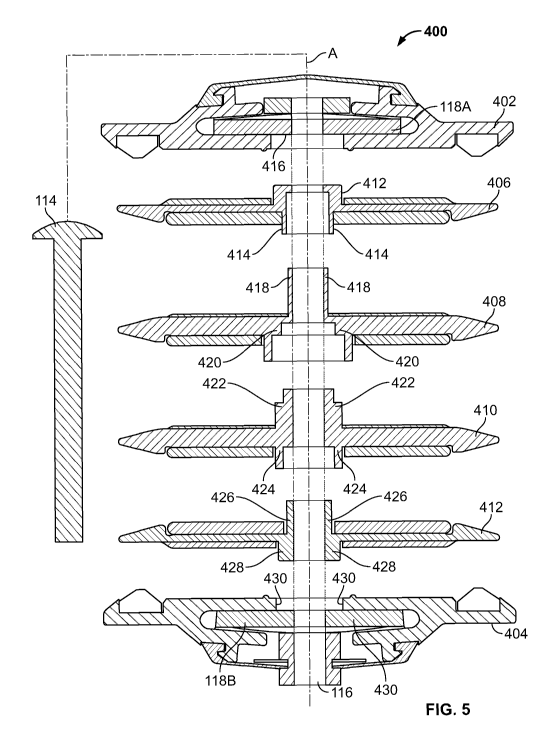
and/or patterns to aid the user in proper assembly. Figure 5 illustrates an
exploded cross-
sectional view of a bus assembly connector 400 having phase members with poka
yoke
features or configurations in accordance with an aspect of the present
disclosure. As shown
in Figure 5, each of the phase members 406, 408, 410 and 412 includes sleeves
that are
distinctly different from one another such that each sleeve will only fit with
only one other
sleeve of another predetermined phase member. In an aspect, it is contemplated
that all of the
phase members have poka yoke features such that all the phase member are
required in
assembling the bus assembly connector 400.
[0040] As discussed above, each phase member 406, 408, 410, 412 includes an
axial sleeve that extends in a vertical direction with respect to the planar
insulating plate,
whereby each axial sleeve includes a top interface area and a bottom interface
area. In
particular, the ground phase member 406 includes an axial sleeve with a top
interface 412 and
a bottom interface 414. The intermediate phase member 408 includes an axial
sleeve with a
top interface 418 and a bottom interface 420. The intermediate phase member
410 includes
an axial sleeve with a top interface 422 and a bottom interface 424. The
ground phase
member 412 includes an axial sleeve with a top interface 426 and a bottom
interface 428. It
should be noted that the number of components in the bus assembly connector
400 is an
example and more or fewer components may be alternatively be used.
[0041] Similarly, the distinctive cross-sectional shape and dimensions of the
bottom interface 414 of intermediate phase member 406 are such that the bottom
interface
CA 02782616 2012-05-31
WO 2011/068759 PCT/US2010/058212
-12-
414 will only receive and mate with the top interface 418 of the intermediate
phase member
408. In other words, attempting to insert the top interface 422, the bottom
interface 424 or
any other interface (except for interface 418) into interface 414 will not
allow the
intermediate phase member 408 to mate or couple with those other interfaces.
Thus,
considering that the top interface 418 mirrors with and fits into the contour,
shape and
dimensions of bottom interface 414, only those two predetermined interfaces
are to be
coupled to one another in assembling the bus assembly connector 400.
[0042] Similarly, the distinctive cross-sectional shape and dimensions of the
bottom interface 414 of intermediate phase member 408 are such that the bottom
interface
414 will only receive and be coupleable to the top interface 418 of the
intermediate phase
member 408. In other words, one who attempts to insert the top interface 422,
the bottom
interface 424 or any other interface (except for interface 418) into the
interface 414 would
find that the intermediate phase member 408 would not mate or couple with
those other
interfaces. Thus, considering that the top interface 418 mirrors the contour,
shape and
dimensions of bottom interface 414, those two predetermined interfaces are to
be coupled to
one another only in assembling the bus assembly connector 400.
[0043] In addition to the top interface 418, the axial sleeve of phase member
408
includes a stepped bottom interface 420. As can be seen in Figure 5, the
stepped
configuration of the bottom interface 420 is distinctly different than any of
the other top and
bottom interfaces, except for the top interface 422 of phase member 410 that
mirrors with and
fits into the stepped configuration of bottom interface 420. Thus, the top
interface 422 of the
phase member 410 mates with the stepped bottom interface 420 of the
intermediate phase
member 408 when assembling the bus assembly connector 400.
[0044] As shown in Figure 5, the bottom interface 424 of the intermediate
phase
member 410 has a notched receiving area, whereby the notched receiving area
has a
distinctive configuration and dimension that allows only the top interface 426
of the ground
phase member 412 to be inserted therein to couple the two phase members 410,
412 together.
Additionally, the bottom interface 428 of the ground phase member 412 has a
shape and
dimension that is distinctively different than any of the other top or bottom
interfaces. In
particular, the bottom interface 428 is shaped only to fit within the aperture
430 of the bus
assembly connector cover 404 when the bus assembly connector 400 is assembled.
CA 02782616 2012-05-31
WO 2011/068759 PCT/US2010/058212
-13-
[0045] As discussed above, each of the axial sleeves has top and bottom
interfaces
that are distinctive in shape, dimension and contour and that fit into the top
or bottom
interface of another adjacent predetermined phase member, such that each top
and bottom
interface must couple to the predetermined shaped interface of a predetermined
phase
member in order to successfully assemble the bus assembly connector 400.
Further, although
not necessary, the axial sleeves can be designed such that one or more phase
members cannot
be omitted when assembling the bus assembly connector 400 as the components
will not
securely fasten together. It should be noted that the above description in
Figure 5 is only
exemplary to show the effectiveness of the poka-yoke features incorporated by
the bus
assembly connector, and it is contemplated that any combination of shapes,
dimensions, order
of parts, number of parts can be utilized in achieving the poka-yoke features
without being
limited to the discussion herein. Although it is desired that all of the axial
sleeves are distinct
from one another, it is contemplated that fewer than all the axial sleeves can
have a poka
yoke configuration. As previously mentioned, the axial sleeves, with or
without the poka
yoke features, are desirably configured to fit within one another in a nesting
arrangement to
reduce the phase spaces and thus overall height of the bus assembly connector.
[0046] Additionally, although not necessary, the phase members are configured
such that they must be oriented properly when the phase members are coupled
together. For
example, the axial sleeve 120 (Figure 3) can include a protrusion 132 that
slidably fits within
corresponding slot 211 in axial sleeve 220 (Figure 4) to ensure that the phase
members 106
and 108 are properly oriented. Additionally, the interlocking features of the
axial sleeves
120, 220 limit or prevent the phase members 106, 108 from rotating about one
another about
the axis A when coupled to one another. It should be noted that the
illustrated and described
configurations of the axial sleeve and their respective interfaces are merely
exemplary, it
should be appreciated that the axial sleeves and their respective interfaces
can have any type
of shape, configuration and/or dimension, and is thus not limited to those
shown in the
Figures herein.
[0047] Assembly of the bus assembly connector will now be discussed with
reference to the poka yoke aspect illustrated and discussed in connection with
Figure 5. The
components of the bus assembly connector 400 are arranged and/or stacked from
the top bus
assembly connector cover 402 through the bottom bus assembly connector cover
404: the top
bus assembly connector cover 402; the ground phase member 406; the first
intermediate
CA 02782616 2012-05-31
WO 2011/068759 PCT/US2010/058212
-14-
phase member 408; the second intermediate phase member 410; the ground phase
member
412; the bottom bus assembly connector cover 404; the bolt 114, the nut 116
and the washers
118A and 118B. In addition, it should be noted that each phase member 406,
408, 410 and
412 is associated with one or more conductor plates, which are assumed to be
already be
coupled to the respective phase members 406, 408, 410 and 412.
[0048] During the assembly, ground phase member 412 is coupled with the
bottom bus assembly connector cover 404 by inserting the bottom interface 428
into the
receiving aperture 430. The bottom interface 424 of the intermediate phase
member 410 is
coupled only with the top interface 426 of the ground phase member 412, where
at least a
portion of the bottom interface 424 is inserted into and received by the top
interface 426 such
that the interfaces 424 and 426 nest with one another. The bottom interface
420 of the
intermediate phase member 408 is coupled only with the top interface 422 of
the intermediate
phase member 410, where at least a portion of the bottom interface 420 is
inserted into and
received by the top interface 422 such that the interfaces 420 and 422 nest
with one another.
The bottom interface 414 of ground phase member 406 is coupled only with the
top interface
418 of the intermediate phase member 408, where at least a portion of the
bottom interface
414 is inserted into, and thus received by, the top interface 418 such that
the interfaces 414
and 418 nest with one another. Following, the top interface 412 of ground
phase member 406
is inserted into and coupled only with the receiving aperture 416 of the top
bus assembly
connector cover 402.
[0049] Considering that the insulated axial sleeves of adjacent phase members
406, 408, 410 and 412 vertically overlap with one another along the axis A,
there are no
spacings or breaks between phase members which lack dielectric or insulator
material. The
nesting arrangements of the axial sleeves of phase members 406, 408, 410, and
412 form a
continuous vertical dielectric insulator between the ground phase member 406
and ground
phase member 412 with sufficient dielectric clearances as mandated by
standards.
[0050] Stacking the components in the preceding order automatically aligns the
respective central apertures along the axis A, whereby the washers 118A and
118B are
positioned within the bus assembly connector covers 402, 404. A bolt 114 can
be slid along
the axis A through the common central aperture positioned approximately at a
center of the
bus assembly connector 100. The bolt 114 and the nut 116 are tightened to
secure the
components together, thereby defining the respective spaces of each of the
pairs of opposing
CA 02782616 2012-05-31
WO 2011/068759 PCT/US2010/058212
- 15-
phase members 406, 408, 410 and 412 for slidably engaging therebetween a phase-
conductor
of a bus system. Tightening the bolt 114 and the nut 116 compresses the
washers 118A,
118B, which aids in distributing the compressive load of the bolt 114 and the
nut 115, as well
as securing or locking the nut 116 in place to prevent an accidental loosening
of the nut 115
during use of the bus assembly connector 400 in the bus system 10.
[0051] It should be noted that although a particular order is discussed above
with
regard to the assembly of the bus assembly connector 400 (i.e. beginning from
the bottom bus
assembly connector cover upwards toward the top bus assembly connector cover),
it is
contemplated that the assembly can begin at the top bus assembly connector
cover or
anywhere between the top and bottom bus assembly connector covers. For example
only, it
is possible that assembly begins with coupling of phase members 408 and 410,
whereby the
remaining components are vertically stacked to the coupled phase members 408
and 410.
[0052] As discussed above, the nesting arrangement can also be applied to the
phase conductors, i.e., phase buses, of a bus assembly (i.e., 25A-25C; 26A-26C
in Figure 1).
Figure 6 illustrates an exploded view of a portion of a bus assembly of a bus
assembly section
in accordance with an aspect of the present disclosure where bus phase
conductors 506, 510,
514 are secured against EMF shorting displacement by a center nut and bolt 97,
99
respectively, and suitable nesting dielectrics 504, 508, 512, 516 as further
explained below.
The bus assembly section 500 includes housings 502 and 518 with a phase A bus
(conductor)
506, a phase B bus (conductor) 510, and a phase C bus (conductor) 514, all of
which are
positioned between the housings 502 and 518. Additionally, a first phase
(insulator) member
504 is positioned between the housing 502 and the phase A bus 506. A second
phase
(insulator) member 508 is positioned between the phase A bus 506 and the phase
B bus 510.
Further, a third phase (insulator) member 512 is positioned between the phase
B bus 510 and
the phase C bus 514. Moreover, a fourth phase (insulator) member 516 is
positioned between
the phase C bus 514 and the housing 518. It should be noted that the bus
assembly 500
shown in Figure 6 is exemplary, and a fewer or greater number of phase
(insulator) members
and/or phase buses (conductors) may be utilized. A pair of washers 98 are
disposed adjacent
to housings 502 and 518, whereby a metallic bolt 99 is slidably inserted into
the commonly
aligned apertures of the individual components. A nut 97 couples to the bolt
99 to secure the
components together in a sandwiched fashion.
CA 02782616 2012-05-31
WO 2011/068759 PCT/US2010/058212
- 16-
[0053] In general, each phase (insulator) member shown in Figure 6 includes an
insulated axial sleeve with an aperture along the axis B. Further, each
insulator member
includes a substantially flat rectangular insulator plate that is desirably
integral with the axial
sleeve and extends along a plane substantially perpendicular to the axial
sleeve. In particular,
the insulator member 504 includes an axial sleeve 520; the insulator member
508 includes an
axial sleeve 522; the insulator member 512 includes an axial sleeve 524; and
the insulator
member 516 includes an axial sleeve 526. Although the axial sleeves 520, 522,
524 and 526
are shown to have a circular cylindrical cross-section along axis B, it is
contemplated that one
or more of the axial sleeves 520, 522 524, 526 include a header portion which
traverses along
the plane parallel to the insulator member and comes into contact with the bus
(conductor)
member, as further described below.
[0054] It should be noted that the plane insulator members and the axial
sleeves
can be any size or cross-sectional shape dictated by electrical and mechanical
needs. In an
aspect, one or more of the axial sleeves are configured to fit at least
partially within one or
more other axial sleeves to create a nesting assembly. Further, it is
contemplated that one or
more of the axial sleeves can have distinctive poka yoke configurations that
require that their
insulator members be located adjacent to one or more predetermined bus members
and
coupled together in a predetermined order when assembling the bus assembly.
[0055] Figure 7 illustrates an exploded cross-sectional view of a portion of
the bus
assembly 500 in accordance with an aspect of the present disclosure. As shown
in Figure 7,
the axial sleeve 520 of the first insulator member 504 includes an aperture
503 within a
circular-shaped first inner wall 528, whereby the aperture 503 allows the bolt
99 to be
slidably inserted therethrough along the axis B. The sleeve 520 also includes
a first outer
circular wall 530 that is concentric with the first inner wall 528 about axis
B, whereby a
circular-shaped first receiving area 532 is located between the first inner
and first outer walls
528, 530.
[0056] Additionally, the sleeve 522 of the second insulator member 508
includes
an aperture 507 within a circular-shaped second inner wall 534. The sleeve 522
also includes
a second outer circular-shaped wall 536 that is concentric with the second
inner wall 534
about the axis B, whereby a circular-shaped second receiving area 538 is
located between the
second inner and second outer walls 534, 536.
CA 02782616 2012-05-31
WO 2011/068759 PCT/US2010/058212
-17-
[0057] As shown in Figure 7, the sleeve 524 of the third insulator member 512
includes an aperture 511 within a circular-shaped third inner wall 540. The
sleeve 524 also
includes a circular-shaped third intermediate wall 542 that is concentric with
the third inner
wall 540 about the axis B, whereby a circular-shaped third inner receiving
area 544 is located
between the third inner and second outer walls 540, 542. Additionally, a
circular-shaped
third outer wall 546 concentric with walls 540 and 542 is located at an outer-
most diametric
position of the sleeve 524, with respect to the axis B. The third outer wall
546 is positioned a
distance to form circular-shaped third outer receiving area 548 between walls
542 and 546.
[0058] Further, the sleeve 526 of the fourth insulator member 516 includes an
aperture 515 within a circular-shaped fourth inner wall 550 about the axis B.
The sleeve 526
also includes a circular-shaped fourth outer wall 552 that is concentric with
the fourth inner
wall 550 about the axis B, whereby a circular-shaped fourth receiving area 534
is located
between the walls 550 and 552.
[0059] In the example, each axial sleeve is designed such that predetermined
walls and/or receiving areas of one or more other axial sleeves fit in a
designated location to
create a nesting arrangement. Figure 8 illustrates the axial sleeves in Figure
7 in the
assembled state in accordance with an aspect of the present disclosure.
[0060] In particular, as shown in Figure 8, with respect to the sleeve 503,
the third
wall 540 and the second wall 550 nest within the receiving area 532 (Figure 7)
of the first
insulator 504. From Figure 7, additionally, the fourth wall 530 and the fifth
wall 534 nest
within the receiving area 544 of the third insulator 512. Further, the sixth
wall 542 nests
within the receiving area 538, whereas the fourth outer wall 552 nests within
the third outer
receiving area 548. As shown, each axial sleeve is designed such that all the
insulator
members must be coupled in a predetermined order with each insulator member at
a
predetermined vertical position with respect to the remaining insulator
members.
[0061] The several overlapping, nested axial sleeves allow the insulator
material
to interface between the energized phase bus assemblies along the axis B while
retaining the
dielectric clearances necessary for purposes of clamping the bus assemblies
for short circuit
bracing. The nesting arrangement allows the metallic bolt 99 to pass through
the closely
spaced phase buses to clamp or otherwise secure the components of the bus
assembly
together without compromising the dielectric clearance and creepage ratings.
The particular
nested arrangement shown in Figure 8 is based on the particular voltage and
power ratings
CA 02782616 2012-05-31
WO 2011/068759 PCT/US2010/058212
-18-
with which the bus assembly 500 is to be used, and therefore may be altered
depending on the
particular required voltage and power ratings of the bus assembly 500.
[0062] While particular aspects and applications of the present disclosure
have
been illustrated and described, it is to be understood that the present
disclosure is not limited
to the precise construction and compositions disclosed herein and that various
modifications,
changes, and variations may be apparent from the foregoing descriptions
without departing
from the spirit and scope of the present disclosure as defined in the appended
claims.