Note: Descriptions are shown in the official language in which they were submitted.
CA 02782668 2012-06-26
INSULATED CONTAINER WITH WORK SURFACE
Field of the Invention
This invention relates to the field of portable insulated containers.
Background of the Invention
Portable, soft-sided insulated containers may be used to transport articles
that may best
be served cool, such as beverages or salads, or warm, such as appetizers, hot
dogs, and so on.
Such containers are also used to carry liquids, whether hot liquids, such as
soup containers,
coffee or tea, or cold liquids such as beer, soft drinks, or other carbonated
beverages, juices and
milk. The containers are typically made in a generally cube-like shape,
whether of sides are of
equal length or not, having a base, four upstanding walls, and a top. The top
wall is often a lid
which opens to permit articles to be placed in, or retrieved from, the
container. In soft-sided
coolers, the main closure of the lid has tended to depend on the closing of a
zipper, often a
zipper running around three sides of a rectangle, with the fourth side being
hinged.
It may be that some people would prefer not to have the sometimes cumbersome
bother
of opening the main closure, particularly if it requires the use of two hands,
and if the process is
awkward. They may prefer the use of a closure member that can be used with one
hand, such
as a zipperless closure member. Further, while opening the main closure member
to fill the
insulated container may be appropriate, and may occur in the kitchen or at
another loading
location where full access is desired and convenient, it may also be that when
the unit is being
used, opening the full main closure member may lead to more rapid heat loss
(or gain, as may
be) than if a smaller, auxiliary, closure member were used.
Furthermore, when an object is removed from the cooler, it may be that it
would be
convenient to have some place to rest that object temporarily. It may be that
one wishes to put
down a drink in a glass while reaching for a can of ginger ale or cola to
freshen a drink, or to
have a place where a lemon or lime can be sliced suitably. For whatever
reason, it may be
desirable to have a place for resting objects, even if merely to free one's
hand to close the
cooler. It may also be convenient for that resting place to be adjacent to the
easily accessed
opening; for that resting place to be firm, such that objects placed upon it
may be less prone to
wobble or tip, and for that resting place to be washable such that it may be
wiped clean with a
cloth should drinks or other objects be spilled on it. Further still, it may
be convenient for that
CA 02782668 2012-06-26
- 2 -
resting place to be such as may discourage, or limit, the extent to which
objects may slide if the
surface is not precisely level, as may be the case at a pic-nic, at a sporting
venue, or at the
beach.
In the event that the insulated container is a collapsible insulated container
that may be
collapsed or folded to a collapsed position when not in use, it may be that a
rigid working
surface, or table top, however it may be called, may be mounted in such a way
as not to obstruct
movement of the assembly to the folded or collapsed, or storage condition.
Alternatively, the
rigidity of the work surface may define a frame, or stiffening member, that,
when in place, may
tend to encourage the assembly to maintain its shape when in use.
Summary of the Invention
In an aspect of the invention there is a soft-sided insulated container, or
container
assembly, having a rigid member defining a table top. In an additional feature
of that aspect of
the invention the rigid member may be an upper member of the container or
container
assembly. In a further feature is may include an element adapted to discourage
objects from
sliding thereoff.
In a further feature of that aspect of the invention, the closure member is
movable to
govern internal access to the container. In another feature the closure member
is a zipperless
closure member. In still another feature, the soft-sided insulated container
is movable between
folded position and an expanded position and has securements operable
releasably to secure the
container in the folded position.
In another aspect of the invention there is a soft-sided insulated container
having a body
and a top. The body has a soft-sided insulated wall structure defining a
cavity therewithin in
which to receive objects. At least a portion of the top defines a first
closure member of the
insulated container, the first closure member being movable between a closed
position and an
open position to govern access to the cavity. The top includes a rigid member;
and, when the
first closure member is in the closed position, the rigid member defines an
externally accessible
work surface upon which to place objects.
In another feature of that aspect of the invention the rigid member overlies
an insulated
layer portion of the top. In still another feature, the top panel has a
breadth and a width, and the
CA 02782668 2012-06-26
- 3 -
rigid member has at least one of (a) a breadth less than the breadth of the
top panel; and (b) a
width that is less than the width of the top. In yet another feature, the
rigid member spans the
top panel in one direction. In a further feature, the top has a front edge and
an opposed rear
edge, a left hand edge and an opposed right hand edge, and the rigid panel
spans the top cross-
wise between the left hand and right hand edges. In still yet another feature,
the rigid member
has a margin running along the front edge of the top. In an additional
feature, the rear edge of
the top is hingedly connected to the body of the container, and the rigid
member has rear
margin spaced from the rear edge of the top. In yet another additional
feature, a rearward
portion of the top is defined between the rear edge of the top and the rear
margin of the rigid
member, and the rearward portion of the top is pliable, permitting the
rearward portion to bend
on a curve. In still another feature, the top has one of: (a) an inset
secondary closure member
adjacent to the rigid member; and (b) an inset secondary closure member formed
amidst the
rigid member. In a further feature, the secondary closure member is a
zipperless closure
member, the secondary closure member is pivots on a hinged connection, and the
secondary
closure member is oriented to open toward a largest portion of the work
surface.
In another feature, the top is hingedly mounted to the body of the container.
In an
additional feature, the body has an upper margin defining a periphery of an
opening of the
cavity, the top is movable to mate with the periphery of the opening; and the
rigid member is
smaller than the opening. In a yet further feature, the top has a front margin
and an opposed
rear margin, a left hand margin and an opposed right hand margin; the top is
hingedly
connected to the body along the rear margin, and the rigid member spans the
top in one
direction. In a still further feature, the rigid member has a first margin
portion running along at
least part of the left hand margin of the top; a second margin portion running
along at least part
of the front margin of the top, and a third margin portion running along at
least part of the right
hand margin of the top. In another feature, the top has a front margin and an
opposed rear
margin, a left hand margin and an opposed right hand margin; and the rigid
member spans the
top in one direction.
In still another feature, the top has a first portion and a second portion;
the first portion
is proximate to the connection of the top to the body; the second portion is
distant from the
connection to the body; and the second portion includes the rigid member. In a
further feature,
the container has a secondary closure member that is one of (a) an inset
secondary closure
member adjacent to the rigid member; and (b) an inset secondary closure member
formed
amidst the rigid member. In another feature, the secondary closure member is a
zipperless
CA 02782668 2012-06-26
- 4 -
closure member, the secondary closure member pivots on a hinged connection,
and the
secondary closure member is oriented to open toward a largest portion of the
work surface.
In still another feature, the body has a front wall, a rear wall, a left hand
wall and a right
hand wall. The front wall has a width and a height. The rear wall has an upper
margin. The
top is hingedly connected to the upper margin of the rear wall. The top has a
proximal portion
adjacent to the upper margin of the rear wall, and a distal portion distant
from the upper margin
of the rear wall. The distal portion includes the rigid member. The rigid
member has a width
and length, the width being measured predominantly parallel to the upper
margin of the rear
wall, and the length being measured cross-wise to the width. The length of the
rigid member is
one of (a) less than, and (b) equal to, the height of the front wall of the
body. In yet another
feature, the work surface includes a portion bounded by a peripheral retaining
wall, whereby
when the rigid member is other than precisely level the retaining wall is
operable to discourage
objects placed on the work surface from sliding off the work surface.
In still yet another feature, the body is movable between an expanded position
and a
folded position, the body having securements operable releasably to retain the
body in the
folded position. In an additional feature, the rigid member overlies an
insulated layer portion of
the top. In another feature, the top panel has a breadth and a width, and the
rigid member has at
least one of (a) a breadth less than the breadth of the top panel; and (b) a
width that is less than
the width of the top. In still another feature, the rigid member spans the top
panel in one
direction. In another feature, the top has a front edge and an opposed rear
edge, a left hand
edge and an opposed right hand edge, and the rigid panel spans the top cross-
wise between the
left hand and right hand edges. In a further additional feature, the rigid
member has a margin
running along the front edge of the top. In a yet further feature, the rear
edge of the top is
hingedly connected to the body of the container, and the rigid member has rear
margin spaced
from the rear edge of the top. In a still further feature, a rearward portion
of the top is defined
between the rear edge of the top and the rear margin of the rigid member, and
the rearward
portion of the top is pliable, permitting the rearward portion to bend on a
curve.
In another feature, the top has one of: (a) an inset secondary closure member
adjacent to
the rigid member; and (b) an inset secondary closure member formed amidst the
rigid member.
In another feature, the secondary closure member is a zipperless closure
member, the secondary
closure member is pivots on a hinged connection, and the secondary closure
member is oriented
to open toward a largest portion of the work surface. In another feature, the
top is hingedly
CA 02782668 2012-06-26
- 5 -
mounted to the body of the container. In an additional feature, the body has
an upper margin
defining a periphery of an opening of the cavity, the top is movable to mate
with the periphery
of the opening; and the rigid member is smaller than the opening. In another
feature, the top
has a front margin and an opposed rear margin, a left hand margin and an
opposed right hand
margin; the top is hingedly connected to the body along the rear margin, and
the rigid member
spans the top in one direction. In still another feature, the rigid member has
a first margin
portion running along at least part of the left hand margin of the top; a
second margin portion
running along at least part of the front margin of the top, and a third margin
portion running
along at least part of the right hand margin of the top.
In another feature, the top has a front margin and an opposed rear margin, a
left hand
margin and an opposed right hand margin; and the rigid member spans the top in
one direction.
In yet another feature, the top has a first portion and a second portion; the
first portion is
proximate to the connection of the top to the body; the second portion is
distant from the
connection to the body; and the second portion includes the rigid member. In
still another
feature, the container has a secondary closure member that is one of (a) an
inset secondary
closure member adjacent to the rigid member; and (b) an inset secondary
closure member
formed amidst the rigid member. In an additional feature, the secondary
closure member is a
zipperless closure member, the secondary closure member is pivots on a hinged
connection, and
the secondary closure member is oriented to open toward a largest portion of
the work surface.
In another feature, the body has a front wall, a rear wall, a left hand wall
and a right
hand wall. The front wall has a width and a height. The rear wall has an upper
margin. The
top is hingedly connected to the upper margin of the rear wall. The top has a
proximal portion
adjacent to the upper margin of the rear wall, and a distal portion distant
from the upper margin
of the rear wall. The distal portion includes the rigid member. The rigid
member has a width
and length, the width being measured predominantly parallel to the upper
margin of the rigid
member, and the length being measured cross-wise to the width; and the length
of the rigid
member is one of (a) less than, and (b) equal to, the height of the front wall
of the body. In
another feature, the work surface includes a portion bounded by a peripheral
retaining wall,
whereby when the rigid member is other than precisely level the retaining wall
is operable to
discourage objects placed on the work surface from sliding off the work
surface.
In still the body has a front wall, a rear wall, a left hand wall and a right
hand wall. The
front wall has a width and a height. The rear wall has an upper margin. The
top is hingedly
CA 02782668 2012-06-26
- 6 -
connected to the upper margin of the rear wall. In the expanded position, the
body has an upper
margin defining a periphery of an opening of the cavity, the top is movable to
mate with the
periphery of the opening; and the rigid member is smaller than the opening.
The top has a
proximal portion adjacent to the upper margin of the rear wall, and a distal
portion distant from
the upper margin of the rear wall. The distal portion includes the rigid
member. The rigid
member has a width and length, the width being measured predominantly parallel
to the upper
margin of the rear wall upper margin, and the length being measured cross-wise
to the width.
The length of the rigid member is one of (a) less than, and (b) equal to, the
height of the front
wall of the body; and in the folded position of the body the first portion of
the top panel curves
over the folded body, and the rigid member lies in front of the front wall of
the body with the
work surface facing outwardly and forwardly. In another feature, the container
has a secondary
closure member that is one of (a) an inset secondary closure member adjacent
to the rigid
member; and (b) an inset secondary closure member formed amidst the rigid
member. In an
additional feature, the secondary closure member is a zipperless closure
member, the secondary
closure member pivots on a hinged connection, and the secondary closure member
is oriented to
open toward a largest portion of the work surface.
In another aspect of the invention, there is a soft-sided insulated container
having a rigid
member defining a work surface upon which to rest objects. The body is
collapsible and is
movable between a collapsed position and a non-collapsed position. The top
includes a second
closure member, the second closure member being smaller than the first closure
member. The
rigid member is movable between a first position and a second position, the
first position being
a retracted position, the second position being a deployed position; and when
the body is in the
non-collapsed position, and the work surface member is in the deployed
position, the secondary
closure member is free of obstruction by the work surface member.
In a feature of that aspect of the invention, the rigid member defining the
work surface
includes a folding shelf In an alternate feature, the rigid member is movable
in linear
translation relative to the lid. In another feature, the work surface spans
the lid in at least one of
(a) a side-to-side direction; and (b) a front-to-back direction.
In another aspect of the invention there is any combination of any of the
features of any
one of embodiments shown or described herein, in combination with the features
of any other
embodiment shown or described herein, except to the extent those features are
mutually
CA 02782668 2012-06-26
'
- 7 -
exclusive. In another aspect of the invention, there is any apparatus
substantially as shown or
described herein, in whole or in part.
Brief Description of the Drawings
These aspects and other features of the invention can be understood with the
aid of the
following illustrations of a number of exemplary, and non-limiting,
embodiments of the
principles of the invention in which:
Figure la shows a perspective view taken from in front, above, and to the
right, of an
embodiment of a soft-sided container assembly according to an aspect of the
present invention, the assembly being shown in an expanded condition and with
its auxiliary closure member open;
Figure lb shows the container assembly of Figure la in a perspective view
taken from
above on the opposite diagonal to that of the perspective view of Figure la
and
with the auxiliary closure member closed;
Figure le shows a top view of the container assembly of Figure la;
Figure id shows a bottom view of the container of Figure la;
Figure le is a front view of the container assembly of Figure la;
Figure if is a rear view of the container assembly of Figure la;
Figure lg is a left hand view of the container assembly of Figure la;
Figure lh is a right hand view of the container assembly of Figure la;
Figure 2a shows a perspective view taken from in front, above, and to the
right, the
container assembly of Figure la in a collapsed, or folded, condition;
Figure 2b shows the folded container assembly of Figure 2a in a perspective
view taken
from below, in front, and to the left;
Figure 2c shows the folded container assembly of Figure 2a in a perspective
view taken
from above, behind, and to the right on the opposite diagonal to Figure 2b;
Figure 2d is a front view of the container assembly of Figure 2a;
Figure 2e is a rear view of the container assembly of Figure 2a;
Figure 2f shows a top view of the container assembly of Figure 2a;
Figure 2g shows a bottom view of the container of Figure 2a;
Figure 2h is a left hand view of the container assembly of Figure 2a;
Figure 2i is a right hand view of the container assembly of Figure 2a;
CA 02782668 2012-06-26
- 8 -
Figure 3a shows an isometric view of the container assembly of Figure la,
showing an
auxiliary closure member of the top panel in an open condition, and showing a
front auxiliary compartment closure member in an open position;
Figure 3b shows a top view of the container assembly of Figure 3a from above
with its
auxiliary closure member in an open position;
Figure 3c shows the container assembly of Figure 3a from above and to the left
with the
main closure member thereof in a fully open condition;
Figure 3d is a cross-sectional view of the container assembly of Figure la;
taken on
section '3d ¨ 3d' of Figure lc;
Figure 4a is a top view of a substantially rigid member of the container of
Figure la;
Figure 4b is a view on a lengthwise cross-section of the member of Figure 4a
taken on
section `4b ¨ 4b';
Figure 4c is a view on a lengthwise cross-section of the member of Figure 4a
taken on
section '4c ¨ 4c';
Figure 4d is a view on a lengthwise cross-section of the member of Figure 4a
taken on
section '4d ¨ 4d';
Figure 5a is a perspective view of an alternate arrangement of soft-sided
insulated
container assembly to that of Figure la shown in an expanded condition;
Figure 5b is a perspective view of the soft-sided cooler assembly of Figure 5a
in a
collapsed, retracted, or storage position or configuration;
Figure 5c is an end, view of the soft-sided insulated container assembly of
Figure 5b;
Figure 5d is a front view of the soft-sided container assembly of Figure 5b;
Figure 5e is a top view of the soft-sided insulated container assembly of
Figure 5b;
Figure 6a shows a perspective view of an alternate soft-sided container
assembly to that
of Figure la with a movable work surface member in an extended position;
Figure 6b is a top view of the container assembly of Figure 6a with the work
surface in
a stored or retracted position;
Figure 6c is a front view of the container assembly of Figure 6b;
Figure 6d is an exploded view of a three-part work surface sandwich assembly
used in
the container assembly of Figure 6a;
Figure 6e shows the assembled members of with work surface assembly of Figure
6d in
an extended condition;
Figure 6f shows a top view of the assembly of Figure 6e in a closed or
retracted
position;
CA 02782668 2012-06-26
=
- 9 -
Figure 7a is a perspective view from the front right hand comer of a further
soft-sided
insulated container assembly to that of Figure la, having an extending shelf
assembly mounted to a rear wall thereof;
Figure 7b is a top view of the container assembly of Figure 7a;
Figure 7c is a front view of the container assembly of Figure 7a;
Figure 7d is a developed, that is, unfolded, view of the shelf assembly of the
container
assembly of Figure 7a;
Figure 7e is a perspective view of the shelf assembly of Figure 7d in a
collapsed or
folded position;
Figure 7f is a perspective view of the shelf assembly of Figure 7e in a
partially unfolded
position;
Figure 7g Figure 7f is a perspective view of the shelf assembly of Figure 7e
in a
partially unfolded position;
Figure 7h is a perspective view of the shelf assembly of Figure 7e in a
partially
unfolded position;
Figure 7i is a perspective view of the shelf assembly of Figure 7e in a
partially unfolded
position;
Figure 7j is a side view of the shelf assembly of Figure 7e in a fully folded
position or
condition as in Figure 7e;
Figure 7k is a side view of the shelf assembly of Figure 7j in a partially
unfolded
position;
Figure 71 is a side view of the shelf assembly of Figure 7j in a fully
expanded and
deployed position or condition;
Figure 7m is a scrap perspective view of an alternative shelf assembly to that
of Figure
7j with a drop leaf as opened; and
Figure 7n is a cross-section of the shelf assembly of Figure 7m in a closed,
retracted, or
storage, position.
Detailed Description
The description that follows, and the embodiments described therein, are
provided by
way of illustration of an example, or examples, of particular embodiments of
the principles of
the present invention. These examples are provided for the purposes of
explanation, and not of
limitation, of those principles and of the invention. In the description, like
parts are marked
throughout the specification and the drawings with the same respective
reference numerals.
CA 02782668 2012-06-26
- 10 -
The drawings may be understood to be to scale and in proportion unless
otherwise noted.
Figure 3d is not drawn to scale 9 for example. The wording used herein is
intended to include
both singular and plural where such would be understood, and to include
synonyms or
analogous terminology to the terminology used, and to include equivalents
thereof in English or
in any language into which this specification many be translated, without
being limited to
specific words or phrases.
For the purposes of this description, it may be that a Cartesian frame of
reference may
be employed. In such a frame of reference, the long, or largest, dimension of
an object may be
considered to extend in the direction of the x-axis, the base of the article,
where substantially
planar, may be considered to extend in an x-y plane, and the height of the
article may be
measured in the vertical, or z-direction. When the container assembly is
sitting on its bottom
panel, the largest predominantly upstanding panels may be designated
arbitrarily as the front
and rear sides, faces, or portions of the container. Similarly, the closure
member, or opening, of
the bag is arbitrarily designated as being at the top, and the base panel is
designated as being at
the bottom, as these terms may be appropriate for the customary orientation in
which the
objects may usually be found, sold, or employed, notwithstanding that the
objects may be
picked up and placed on one side or another from time to time at the user's
choice. It should
also be understood that, within the normal range of temperatures to which
human food and
human touch is accustomed, although the term cooler, or cooler container, or
cooler bag, may
be used, such insulated structures may generally also be used to keep food,
beverages, or other
objects either warm or hot as well as cool, cold, or frozen. Unless noted
otherwise, the terms
"inside" and "outside", "inwardly" and "outwardly", refer to location or
orientation relative to
the enclosed spaces of the container assembly, as may be.
In this specification reference is made to insulated containers. The adjective
"insulated"
is intended to be given its customary and ordinary meaning as understood by
persons skilled in
the art. It is not intended to encompass single layers, or skins, of
conventional webbing
materials, such as Nylon (t.m.), woven polyester, canvas, cotton, burlap,
leather, paper and so
on, that are not otherwise indicated as having, or being relied upon to have,
particular properties
as effective thermal insulators other than in the context of being provided
with heat transfer
resistant materials or features beyond that of the ordinary sheet materials in
and of themselves.
In this description, when an item, or structure, or wall, is indicated as
being insulated, such term
is understood to mean that the wall has a layer of insulation, as distinct
from merely being a
layer of plastic or canvas, or paper or cardboard, or webbing in and of itself
by virtue of its own
CA 02782668 2012-06-26
,
- 11 -
resistance to heat transfer. For example, an insulated wall may have an outer
surface or skin, or
covering, which, in the context of soft-sided insulated containers may be a
layer of nylon,
which may be a woven or textured nylon. The wall may have an inner surface or
skin, or
covering, such as a vinyl liner or sheet. A layer of insulating material which
may typically be a
closed-cell or open cell foam, may be captured between the inner and outer
skins. This
commentary is provided to supplant any dictionary definition, and to prevent
interpretation in
any Patent Office that strays from the customary and ordinary meaning of the
term "insulated"
as provided herein.
Similarly, this description may tend to discuss various embodiments of soft-
sided
containers, as opposed to hard shell containers. In the jargon of the trade, a
soft sided cooler, or
bag, or container, is one that does not have a substantially rigid, high
density exoskeleton
(typically a molded shell, e.g., of ABS or polyethylene, or other common types
of molded
plastic). Rather, as noted, a soft-sided insulated container wall may tend to
have, for example,
an outer skin, a layer of insulation, and an internal skin, both the internal
and external skins
being of some kind of webbing, be it a woven fabric, a nylon sheet, or some
other membrane.
The layer of insulation, which may be a sandwich of various components, is
typically a flexible
or resilient layer, perhaps of a relatively soft and flexible foam.
A soft-sided container may still be a soft-sided container where, as described
herein, it
may include one or more substantially rigid internal liners that seat within
the soft-sided wall
structure, or it may include one or more battens (which may be of a relatively
hard plastic)
concealed within the soft sided wall structure more generally, or where hard,
moulded, fittings
may be used whether at a container rim or lip, or to provide a base or a
mounting point for
wheels, but where the outside of the assembly is predominantly of soft-sided
panels. Again, this
definition is intended to forestall interpretation by any patent office of the
term "soft-sided" in a
manner that diverges from the ordinary and customary meaning of the term as
understood by
persons of ordinary skill in the art in the industry, and as explained herein.
Further, in this description, when an object is indicated as being
collapsible, the
meaning is of being intentionally collapsible, or foldable, as opposed to
being something the
will crush if subject to sufficient force. A collapsible container is one that
moves between a
known, collapsed position, and a known deployed, or expanded, position.
CA 02782668 2012-06-26
=
- 12 -
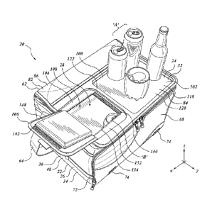
Referring to the Figures, and by way of a general overview, a soft-sided
insulated
container assembly is indicated generally as 20. Container assembly 20 has a
first, or main,
portion, or body, 22, and a second part or portion, 24, that co-operates with
first portion 22.
Typically, the main portion or body 22 has a wall structure, or outer casing,
26 that defines an
internal volume, or cavity, receptacle, or chamber, 28, however it may be
termed, for receiving
objects such as may be desired to be kept cool or warm, a variety of such
objects being
indicated in Figure la as 'A' and 'W. Outer casing 26 may be in the nature of
a soft-sided,
insulated wall structure 34, as described below. Second portion 24 may be, or
include, a top
wall or top panel that defines a closure member, or lid, 32, movable between
open and closed
positions to govern access to the interior of main body 22. Lid 32 may define
a first main or
primary closure member of container assembly. Where it is desired to contain
liquids, container
assembly 22 may include a liner 30 for use within wall structure 26. To the
extent that main
body, or portion, 22 includes an internal liner 30, in one embodiment that
liner 30 may be made
by folding a monolithic plastic sheet, typically a clear plastic vinyl sheet,
with the corners
folded as shown and described in US Patent 6,582,124 issued June 24, 2003.
Liner 30 may
have an upper margin, and may be releasably secured at that upper margin by a
tracked
fastener, or by hook-and-eye fabric strip fasteners, or a combination thereof,
such that liner 30
is watertight, and is removable from within wall structure 28, and of
container assembly 20
more generally, for example to facilitate washing or replacement thereof.
Outer Casing 26
Outer casing 26 may be made of an insulative material 37 for thermally
insulating
chamber 28. The insulative material 37 may be located between an outer
covering 36 and an
inner surface sheet 38. The insulative material inhibits heat transfer between
chamber 28 and
the surroundings of container assembly 20. This may tend to help to maintain a
temperature of
items such as food products stored within the receptacle, i.e., chamber 28,
whether cooler or
warmer, as may be. When lid 32 is in a closed position, heat transfer may be
inhibited to a
greater extent. Insulative material 37 may additionally be soft, such as a
resilient foam, whether
closed cell or open cell, so that the container may tend not to damage, or be
damaged by,
objects with which it may come into contact. If a suitable plastic or other
material or stain
resistant surface coating or surface treatment is used, then outer casing 26
may also be readily
cleaned to remove dirt and other debris acquired through use.
CA 02782668 2012-06-26
- 13 -
Outer casing 26 may have an insulated bottom panel 40, and insulated wall
panels,
namely a front panel 42, a rear panel 44, and a pair of left-hand and right-
hand end panels, or
side panels, 46 and 48. The choice of front and rear, left and right, is
arbitrary. However, for
the purposes of this description rear panel 44 may be understood as the panel
having an upper
margin to which lid 24 is attached, and front panel 42 is the panel opposed to
rear panel 64 and
distant therefrom. Although other embodiments can be made, typically, the
front and rear
panels may lie predominantly in x-z planes; the end or side panels may lie
predominantly in y-z
planes, and the bottom panel may lie predominantly, in an x-y plane, the
various wall panels co-
operating to define five sides of a box, with an internal cavity, or volume,
for receiving objects
to be kept warm or cool as may be, identified as chamber 28. Each panel 40,
42, 44, 46 and 48
may be located at substantially right angles to two adjacent wall panels. For
example, panel 44
is located adjacent panel 46 at one end, and adjacent panel 48 at an opposite
end. The bottom
panel may be attached to all four panels 42, 44, 46 and 48, along edges
thereof Bottom panel
40 and panels 42, 44, 46 and 48, may typically be rectangular, with respective
opposite panels
42 and 44, and 46 and 48. In this configuration, chamber 28 is a generally
cube-like. Panels 42,
44,46 and 48, and bottom panel 40 may be fastened to one another by sewing,
gluing or some
other suitable fastening means. The front, left hand side and right hand side
panels 42,46 and
48, may be made from a single piece of insulated material. Lid 32, rear panel
44 and bottom
panel 40 may also be formed from a single piece of material. For example, rear
panel 44 and
lid 32 may be formed from a single piece of material having a fold therein, as
at hinge 62, to
define rear panel 44 and lid 32. It may be noted that lid 32 may thusly be
connected to the
upper margin of rear panel 44 by a flexible fabric hinge.
In alternative embodiments, outer casing 26 may have either less than four, or
more than
four, predominantly upright panels (not shown). For example, outer casing 26
may be
configured to have one continuous panel defining a round wall, thereby forming
a right
cylinder, or some other generally rounded shape.
Chamber 28 may have a lip or rim, 50, which may define the main or primary
opening
60 through which objects may be introduced into or withdrawn from chamber 28
of container
assembly 20. Panels 42, 44, 46 and 48 may each have an upper, or distal, edge
or margin 52,
54, 56 and 58, respectively, which in the case of edges or margins 52, 56 and
58 is also a free
edge. Margin 54 may be, or may terminate at, a hinge 62, which may be a fabric
or web hinge.
The four margins 52, 54, 56 and 58 co-operate to define a periphery bounding
main container
opening 60. Lid 32 is hingedly, or pivotally attached to rear panel margin 54,
as indicated at
hinge 62, and is movable pivotally about its rearward hinged edge between the
closed, or sealed
CA 02782668 2012-06-26
=
- 14 -
position, and an open, and unsealed, position, thereby governing access the
interior of the
assembly, namely to chamber 28 and thereby to permit or obstruct the
introduction or
withdrawal of objects to be received in the container. In the closed position,
lid 32 may be
secured in place by a tracked closure member, such as the zipper shown in the
illustrations.
Outer casing 26 may have a lifting member, such as a shoulder strap 64
attached thereto, for
example, at side panels 46 and 48.
Figure 3d, in which thicknesses may have been exaggerated as the purpose of
illustration shows the general structure of a cross-section of any of the
insulated wall panels,
revealing the layers of construction. With the exception of auxiliary pouch
24, this section is
typical not only of front panel 42 but also, generally, of rear panel 44, side
panels 46 and 48,
bottom panel 40. The outer layer, or facing, or covering, 36, of the panel (be
it 42, 44,46 or 48)
is an outer skin which in the nature of a nylon, woven nylon, canvas or other
covering layer 68,
which may tend to be abrasion resistant. It overlays an intermediate thermal
insulation
medium, such as may be in the nature of closed cell foam insulation layer 37
for impeding,
which is to say discouraging, heat transfer between the interior of container
assembly 20 and
external ambient. The inner face of the insulated wall panel, namely inner
surface sheet 38,
may be an inner skin which may be in the nature of a flexible sheet, whether
of vinyl (t.m.) or
of plasticised metallic foil sheeting that is shiny and reflective. The
metallic foil sheeting
material may be the type sold under the name Therma-Flect (t.m.). This same
general structural
arrangement prevails in bottom panel 40, although outer covering layer 66 may
be a rather
thicker, scuff-resistant material than the outer skin of the upwardly
extending side walls.
Container assembly 20 may include a further, or secondary, wall panel, or wall
panel
assembly 68 that may be mounted to the front face of front panel 42 to define
a secondary
enclosure, chamber, pocket, pouch, receptacle or compartment, however it may
be named,
indicated at 70. Although the embodiment of wall panel assembly 68 shown is
insulated, in
other embodiments this insulation may be optional. Wall panel assembly may
extend across
substantially the entire width of front panel 42, or only a portion thereof,
and may extend over
substantially the full height of wall panel 42, or a lesser portion thereof.
Some embodiments of
container assembly 20 may not include wall panel assembly 68. Wall panel
assembly 68 may
include a closure member, and that closure member may include a tracked
fastener, such as a
zipper, or such other fastening fitting or fittings as may be appropriate,
indicated as 72. The
lower portion of wall panel assembly 68, or if no such wall panel 68 is used,
then the lower
portion of front panel 42, may have securement fittings, such as indicated at
74.
CA 02782668 2012-06-26
- 15 -
To the extent that a liner 30 is employed, it may be a folded vinyl liner,
which may be a
clear vinyl liner, and liner 30 may be removable and washable. Liner 30 may
have the same
generally box-shaped form as chamber 28, and may fit therewithin accordingly.
The top side of
liner 30 is typically open, corresponding to opening 60, and the upper edge or
periphery of liner
30 may typically be sewn into a seam. It may have a zipper half 55 sewn along
the edges of
three sides, those three sides mating with the opposing zipper half of zipper
55 mounted to the
three free edges, at respective upper margins 52, 56 and 58, of casing 26. The
upper edge,
margin 54, of the rear wall of liner 30 may include a hook-and-eye fabric
fastening strip (e.g.,
Velcro (t.m.)) as at 76 for mating with a corresponding hook-and-eye fabric
fastening strip 78
mounted to the upper margin of the inside face of rear panel 44.
Turning now to the top panel of container assembly 20, namely that panel
defining lid
32, as noted it is movable between first and second positions, one position
being relatively more
obstructive of opening 60 than the other. The top panel, or lid, 32 may be
sized generally to fit
opening 60. That is, to the extent that opening 60 can be said to have a shape
and size, which
may be taken as a projection in the z-direction such as may give a footprint
of that opening, lid
32 may have a corresponding shape and size or footprint. In some embodiments
the footprint of
opening 60, and lid 32, may correspond also to the footprint of bottom panel
40.
Lid 32 may have a first portion, 82, and a second portion 84. Taking the
juncture of
hinge 62 at the upper margin 54 of rear panel 44 as a reference datum, first
portion 82 may be
referred to as a proximal portion, and second portion 84 may be referred to as
a distal portion.
From outside to inside, proximal portion 82 may include an outer surface layer
86, a flexible
reinforcement or batten 88, a layer of insulation, 90, and an inner surface
layer 92. Outer
surface layer 86 may be a flexible fabric web, or plastic sheet, which may be
a woven fabric.
The flexible reinforcement, 88, which may be employed in some embodiments, may
tend to
function to protect the layer of insulation, and also to function as a spring.
Flexible
reinforcement 88, when used, may be placed either inside or outside layer of
insulation 90 and
functions to provide a higher resistance to bending than merely insulation
layer 90 by itself,
such that first portion 82 is more resistant to bending than the soft-sided
wall structure
generally, and may tend to form a curve, or curl, rather than a crease, when
bent. It may be
noted that while reinforcement 88 is soft, or springy, or complaint, in
bending out-of-plane,
namely-out-of-the-x-y plane, (as when lid 32 is folded about the other panels
in the collapsed
and secured configuration shown in Figures 2a, 2b, 2c, 2h and 21,
reinforcement 88 is relatively
CA 02782668 2012-06-26
- 16 -
stiff in resisting in-plane (i.e., in the x-y plane) shear in the x-direction
(i.e., as when a shear
force in the ¨x direction is placed upon the proximal margin of reinforcement
88 at hinge 62,
and a reaction shear force in the +x direction is placed upon the
corresponding distal margin of
reinforcement 88).
In some embodiments container assembly 20 may be collapsible. That is, in
those
embodiments container assembly 20 is movable between a first position, which
may be
identified as the expanded or deployed condition or position shown in the
first series of Figures
la to lh, and a second position, which may be identified as a collapsed or
retracted or folded, or
storage position, whatever terminology may be used, as shown in the second
series of Figures
2a ¨ 2i. Those first and second positions are pre-determined, deliberate,
repeatable
configurations of container assembly 20. Container assembly 20 may include
securements, or
securement fittings 94, which may be hook-and-eye fabric strips, that are
engaged by mating
fasteners such as found at the end of retaining straps 96, whereby the
container assembly 20 is
secured in the collapsed position or condition. The distal margin of lid 32
may similarly have
lid underside securement fittings 98 for engagement in the collapsed position
with securement
fittings 74. It may be noted that in the folded position front panel 42
maintains, or substantially
maintains, a generally planar and parallel orientation relative to rear panel
44 (keeping in mind
the general flexibility of the structure, the extent to which the panels are
either planar or
precisely parallel is approximate). In collapsing, however, side panels 46 and
48, and bottom
panel 40, fold as seen in Figures 2a, 2b, 2c, 2g, 2h and 21. As folded, the
spacing of the front
face of front panel 42 from the front face of rear panel 44 is then a function
of the double-folded
thickness of the side panels 46, 48 plus the thickness of front panel 42.
In the expanded or deployed position, container assembly may be in its
accustomed
form of a generally cube-like squarish or rectangular box. In this position or
condition, lid 32
pivots between open and closed positions on hinge 62, and may have a generally
flat condition.
By contrast, in the collapsed or folded position the distance in the y-
direction from the front
face of rear panel 44 to the front face of front panel 42 is non-trivial.
However, in this
condition proximal portion 82 functions, in effect, as a large extended hinge
that curves or curls
over or reaches about, the other elements of container assembly 20, the reach
of proximal
portion 82 being sufficient to permit distal portion 84 to seat against, front
panel 42, and to be
secured thereto by the engagement of lid underside securement fittings 98 with
securement
fittings 74.
CA 02782668 2012-06-26
- 17 -
Second portion 84 may define or include a substantially rigid member 100,
having a
work surface. That work surface may be referred to for convenience as a table
top, 110. In
some embodiments, second portion 84 (and hence table top 110), may amount to
all, or nearly
all, of lid 32 from hinge 62 to the most distant extremity of lid 32 (that is,
there may be little or
no "first portion"). Alternatively, the relative proportions of first portion
82 to second portion
84, in terms of respective lengths in the x-direction, L82 and L84, may be in
the range of 0 <L82
/L84 < 1/2, and perhaps 1/5 <L82 /L84 <2/5, and perhaps more narrowly, 'A <L82
/L84 < 1/5., it
being understood that the length of lid 32 in the y-direction may generally be
the sum of L82
and L84.
Similarly, in some embodiments, as in the collapsible embodiment noted above,
main
body 22 may have a height in the z-direction, that height being the distance
from the bottom
surface of bottom panel 40 to rim 50, and being substantially the same (if not
identical to) the z-
direction extent of front panel 42, such that it may be identified as 1142. In
the embodiment of
Figure la, the length of second portion 84 may be less than or equal to the
height of front panel
42, that is, L82 < h42, such that in the collapsed condition second portion 84
may lie against, or
generally adjacent to, from panel 44 in a compact, folded position, without
interfering with or
obstructing, the ability of body 22 more generally to be folded.
Second portion 84 may include a first region, 102, and a second region 104.
First region
102 may include table top 110. Second region 104 may include a second, or
secondary, or
auxiliary, or alternate, closure member (or closure member assembly) 106 that
provides access
to chamber 28 through a second, or secondary, opening 108.
Substantially rigid member 100 is, or underlies, or defines first region 102,
including
table top 110. In some embodiments it may be that substantially rigid member
100 is of such an
extent that a portion thereof also underlies, or extends about, or defines,
second region 104,
although this need not necessarily be so. In some embodiment the auxiliary
closure member
need not necessarily be reinforced with a rigid member, but may be formed in a
soft-sided,
unreinforced wall panel structure, instead.
Member 100 may have a generally rectangular periphery 112, which lies,
generally in a
first x-y plane Pi 12. Periphery 112 may include a rearward, or proximal,
margin 113 closest to
hinge 62, and adjoining first portion 82 of lid 32; and a distal margin 114
opposite thereto most
distant from hinge 62. Margins 113 and 114 may run generally parallel to hinge
62 in the x-
CA 02782668 2012-06-26
'
- 18 -
direction. Periphery 112 may also include a left hand margin 115 and a right
hand margin 116,
those left and right hand margins being space apart and opposed. When the
cooler is expanded
and lid 32 is closes, margins 115 and 116 may run in the y-direction.
It may be that margin 113 adjoins first portion 82, or, in embodiments in
which there is
no first portion 82, then adjoining hinge 62. It may also be that margin 114
extends along the
distal-most edge of lid 32 farthest from hinge 62 such that member extends the
full length of
second portion 84 in the radial direction relative to hinge 62, which may also
be expressed as
the full length of second portion 84 in the y-direction when lid 32 is closed.
In such instance,
when lid 32 is closed, and the main closure securement, be it a zipper or
other tracked fastener
is in place in a mating, closed, configuration, margin 114 may be adjacent to,
and to run along
part or all of, upper margin 52 of front panel 42.
Similarly, when lid 32 is closed, it may be that left hand margin 115 runs
along the left-
most edge of lid 32, and, for part or all of its run in the y-direction it may
run along upper
margin 56 of left hand end panel 46, and right hand margin 116 may run along
the right-most
edge of lid 32, and, for part or all of its run in the y-direction it may run
along upper margin 58
or right hand end panel 48. Where margins 115 and 116 run along the left-most
and right-most
margins of lid, then member 100 spans the full width of lid 32, or, expressed
differently,
member 100 extends the full length of lid 32 in the x-direction.
Where the margins of member 100 run along the edges of lid 32, overlying the
upper
margins of panels 42, 46 and 48, to such extent as may be, member 100 may tend
locally to
stiffen those upper margins and fix their position. Where the margins of
member 100 run along
any two of them, or are mated to the distal margin of reinforcement member 88,
reinforcement
member 100 may tend to stabilise that upper margin, to stabilise the relative
positions of the
upper margins so linked, and to function as a substantially rigid shear panel
between those wall
panels, thereby tending to maintain (if not to establish) the side wall panels
in rectangular
relation relative to each other, and to maintain the generally rectangular
plan form of container
assembly 20 in the expanded position more generally. When viewed on a
projection in the z-
direction, (with lid 32 closed on rim 50), member 100 may have the same, or
substantially the
same, extent, or footprint, as second portion 84, e.g., in the lengthwise and
widthwise
directions. In other embodiments, table top 100 may be smaller than second
portion 84.
CA 02782668 2012-06-26
- 19 -
Periphery 112 may have a profiled of recessed leg or toe 118 at the outermost
extremity.
The downward step or recess, indicated at 108, may be such that it provides a
seat for fabric
materials that may be sewn or otherwise fastened to it, whereby the fabric may
be flush.
Substantially rigid member 100 presents a work surface 120 upon which objects,
such as
a can, a bottle, or a glass, cup, or tumbler, may be placed. Work surface 112
is oriented to face
away from chamber 28, and may present a cutting board surface upon which an
apple, a lemon
or a lime (or other fruit, or vegetable, or cheese), or a sandwich may be
sliced. It may be made
of, or surfaced with, any suitable rigid material, even such materials as
wood, metal or ceramic.
It may most typically be made of a formed plastic member, such as may be made
from a high
density plastic such as polyurethane sheet, nylon sheet, UHMW plastics, and so
on. The sheet
stock from which table top 100 is moulded or formed may have a nominal
thickness in the
range of perhaps 1/32" to 1/8", but may typically be if the order of 1/16" to
3/32" thick.
Considering the embodiment illustrated in Figures 4a to 4d, first region 102
and
second region 104 lie to either side of an intermediate member 122, which, in
the embodiment
shown, runs in the y-direction across member 100 between margin 113 and margin
114.
First region 102 has a depressed central portion, or central web 124 that is
surrounded at
its various edges by margins 113, 114, 115 and intermediate member 122.
Central portion or
web 124 may be substantially flat and planar, and may lie in a plane P124 that
is substantially
parallel to, and offset from, plane P112. In each case depressed central
portion 124 is adjoined
by a web or wall 126 that stands predominantly in the z-direction joining
central portion or web
124 to margins 113, 114, 115 and member 122, whereby the effect is to define
flanges 130
around a flat central portion. The upper, or outwardly facing surface 128 of
central web 124
defines the work surface of the table top, or it may be faced with a surface
member or surface
treatment, as may be appropriate, e.g., such as form making a cutting-board
surface, or for
having a no-slip roughened surface to discourage sliding. The peripheral
flange also defined a
retainer, or peripheral wall, that may tend to discourage the sliding of
objects there-off in the
event that cooler assembly 20 is placed on a surface that it not precisely
level, and the may tend
to some extent to retain spills until they can be cleaned up.
It is not necessary that table top 120 defined by surface 128 be square or
rectangular. It
could, for example, be circular, or elliptic, or oblong, as may be. A square
or rectangular
surface of substantial area may be desirable, where the maximum y-direction
width corresponds
CA 02782668 2012-06-26
- 20 -
to 1142, or roughly so. The x-direction extent may be comparable, and in some
embodiments
may be greater, even to the extent of the x-dimension length of lid 32.
Second region 104 may also have a depressed potion 132, which itself may be
substantially planar in an x-y plane P132 offset from plane P112 by some
distance in the z-
direction. This offset distance may be less than, equal to or greater than the
offset distance of
plane P124 from plane P112. Depressed portion 132 is surrounded by part or all
of margins 113,
114, 116 and intermediate member 122, such that, again, the effect is to form
a continuous,
flanged periphery. (In the embodiment illustrated, member 122 effectively
becomes a channel-
section or rib defining a divider between regions 102 and104.) Web 132 has a
central cut-out,
or opening 134. In plan-view, the profile of web 132 may be square, or
rectangular, as may be,
or may have the shape shown, in which one side (at the staff) is straight and
relatively short,
and the distant (or distaff) side is relatively longer, with the remaining two
edges following a
widening or splaying shape, so that the overall outline is that of a
trapezoid, with two sharp
corners and two corners formed on relatively large radii. As assembled, a
closure member 136
is mounted with a fixed edge along one side (the short side), defining a hinge
138. Closure
member may have the form of a flap movable between open and closed positions
to govern
access to chamber 28 through opening 108. A zipperless securement, such as
mating hook-and-
eye fabric fastening strips 140, 142 may be provided to permit the user to
operate closure
member 136 with one hand. Although it is not necessary, it may be convenient
for the distaff
(or distal) edge of closure member 106 to be oriented toward, or amidst, table
top 120, such that
when closure member 106 is open, the flap hangs over the outboard edge of lid
32, tending
thereby not to impede the convenient removal of objects from chamber 28, and
the placement
of those objects, without obstruction, on table top 120. In some embodiments,
the underside, or
inside, of first portion 82 of lid 32 may be lined with an insulating layer
144, and the inner skin
of layer 144 may be a reflective skin. Similarly, the underside of portion 84
may have an
insulation layer 146, which may have a reflective inner skin. The underside of
the flap of
auxiliary closure member 106 may likewise have an insulation layer, or
blanket, as at 148.
In the embodiment of Figures la to lh, the first and second regions of distal
portion 84
are located side-by-side in a left-hand and right-hand orientation, with the
opening of auxiliary
closure member 106 facing toward table top 110. Alternate embodiments are
possible. For
example, closure member 106 could face the front of the unit, i.e., toward
margin 114, or such
other direction as may be appropriate. The arrangement need not be left-hand-
right hand. For
example, in the embodiment of Figure 5a - 5d, soft-sided insulated container
assembly 150 has
CA 02782668 2012-06-26
*
-.21 -
a top wall defining a lid portion, or lid, 152 that includes a rigid member
154 that is
substantially co-extensive with lid portion 152 (and of the footprint of the
base of assembly 150
more generally. Rigid member 154 may include a first portion 156 defining a
work surface, or
table top, 158, and a second portion 160 that defines a zipperless auxiliary
closure member 162.
Closure member 162 has an hinged margin 164 that is located adjacent to the
hinged margin
166 of lid portion 152 more generally. Closure member 162 opens toward table
top 158, i.e.,
toward the center or centroid thereof, but in this instance is mounted along
the rear margin of
lid 152, and is in an intermediate position in the left-to-right width
direction. That position may
be on the centerline of the unit. Rigid member 154 may be a moulding of
relatively deep
section, and may include peripheral retaining features such as a continuous
peripheral lip 168 or
raised corners 170, or both. As seen most clearly in Figure 5c, working
surface 172 of table top
portion, or work surface, 158 is a textured surface with non-slip features.
As shown in the illustrations, the work surface 158 of lid 152 may span the
entire width
of the surface in the x-direction, and may also span the entire depth of the
surface from the rear
edge to the front edge in the y-direction (when the assembly is in the
expanded condition). As
above, it may also form a rigid frame to maintain the general box shape of the
assembly when
deployed. In this configuration, the lower margin of formed rigid member 154
may have a
securement, such as a tracked fastener 155 (e.g., a zipper) by which it is
joined to the lower
portion, or body, 153 of assembly 150 more generally when the assembly is in
the expanded
position and lid 152 is in the closed position relative thereto. When tracked
fastener 155 is
released, lid 152 may be moved to an open position, analogous to that shown in
for assembly 20
in Figure 3c, thereby permitting, for example, loading of container assembly
152 generally.
When assembly 150 is moved to the collapsed position or condition, an internal
flexible
hinge, or web member, 174, which may be made of nylon (t.m.) or other cloth,
or of an
elasticized, or somewhat elasticized, or "stretchy", material, in whole or in
part, permits the rear
margin of lid 152 to separate from the upper margin of the rear wall of body
153, the extended
length of member 174 permitting lid 152 to be folded over the front of the
unit as collapsed,
with member 174 being curved over the collapsed sidewalls in a manner similar
to the curvature
of portion 82 of assembly 20 in the collapsed condition. When assembly 150 is
in the expanded
position, member 174 hangs inside the main internal enclosure of assembly 150,
analogous to
chamber 28 of assembly 20.
CA 02782668 2012-06-26
- 22 -
The secondary members of the structure of assembly 150 may differ from
assembly 20,
as indicated by external pockets 176 and netting 178. In other respects, the
construction of
insulated container assembly 150 is substantially the same as container
assembly 20. The
insulated wall structure construction is the same, and assembly 150 may
include a removable
liner, also as described above. Assembly 150 is a collapsible soft-sided
insulated container
assembly, as shown in Figure 5d. As with container assembly 20, the
substantially rigid
member is of similar length and width to the front face of container assembly
150 more
generally, such that when collapsed as in Figure 5d, the collapsed container
sections nest
against, and have substantially the same projected profile as, rigid member
154.
In another alternate embodiment, Figures 6a ¨ 6h show a soft-sided insulated
container
assembly 180. It has a first portion 182 and a second portion 184. First
portion 182 defines the
lower portion of the container body, and may be taken as being substantially
the same in
construction as main body 22 of container assembly 20, with the exception of
front auxiliary
container compartments 183 and 185 in place of secondary wall panel assembly
68.
Second portion 184 may be taken as being the same as lid portion 32 of
container
assembly 20, having a first portion 186 substantially the same as first
portion 82, differing
therefrom to the extent that second portion 188 of lid portion 184 has an
extendible table top
structure or assembly, identified as substantially rigid assembly 190 in place
of substantially
rigid member 100. To that extent the description of lid portion 32 is not
repeated.
In place of substantially rigid member 100, assembly 190 has a three piece
sandwich
assembly that includes a movable member as described hereinbelow. The first
piece of the
three piece assembly is a base member or base frame, identified as first
substantially rigid
member 192, which has the same arrangement of margins and footprint as member
100, and is
sewn to the underlying fabric and insulation elements of second portion 184 in
the same
manner. Rigid member 192 has a substantially planar central web portion 194
which spans
second portion 188 in the x and y directions, and which is bounded on three
sides of its
periphery by out-of-plane reinforcement members, or flanges, identified as
first (or left hand),
second (or front), and third (or right hand) flanges 196, 197, and 198
respectively that stand in
the z direction out of the x-y plane of central web portion 194. These
reinforcements may also
function as retainers or retaining walls for guiding or inhibiting motion.
While out-of-plane
reinforcements may have many shapes, in the embodiment shown items 196, 197
and 198 have
the form of top-hat, or channel, sections moulded into member 192. The outer
leg 199 of the
CA 02782668 2012-06-26
=
- 23 -
top hat section may be co-planar (or substantially co-planar) with central web
portion 194,
though it may be of thinner section. The resultant U-shaped wall (as seen from
above)
terminates at its rearward margin at left and right hand, turned-in abutments,
or stops, indicated
as 200, 202. Other than stops 200, 202, the rearward margin of member 192 may
be
substantially clear and planar.
Rigid member 192 has a depressed, or stepped-down flanged portion 204 which
has
defined therein an auxiliary opening 206. An auxiliary or secondary closure
member, 210 may
be mounted to flanged portion 204 in substantially the same manner as
auxiliary closure
member 136 is mounted to depressed portion 132. The clear, unimpeded, flat
central portion of
substantially rigid member 192, indicated as 208, defines a first region 212
of member 192, and
depressed flanged portion 204 defines a second region 214 of member 190. First
region, 212,
when exposed defines a first work surface 216 upon which objects may be
placed.
Assembly 190 also includes a second rigid member, 220. Member 220 has a
substantially planar central web portion 222 bounded on three sides of its
periphery by out-of-
plane reinforcement members, or flanges, identified as first (or left hand),
second (or rear), and
third (or right hand) flanges 224, 225, and 226 respectively that form a
continuous three-sided
wall. The rearward reinforcement section may be asymmetric, having a longer
outboard
depending leg. The other reinforcements may also have the form of channel
sections, and may
function as retainers or retaining walls. While out-of-plane reinforcements
may have many
shapes, in the embodiment shown items 224, 225 and 226 have the form of a
channel, sections
moulded into the respective peripheral edges of member 220. A further flange,
in the form of a
channel section 230, may be formed along the front margin of web portion 222
and define a
reinforced edge, or flange thereof. At the front-ward corners of the left and
right hand margins
are shown outwardly protruding abutments, or stops 232, 234 respectively.
Second member
220, or the central web portion thereof may be made of a see-through, i.e.,
transparent material.
The central web portion of second member 220 defines another work surface 228.
Work
surface 228 is a movable work surface that may translate between a first,
retracted or storage
position entirely or predominantly overlying first member 192, and a second,
extended or
deployed position or condition less predominantly overlying member 192, and in
which second
position member 192 may be predominantly or entirely exposed, and member 220,
or a
substantial portion thereof may be moved to a cantilevered position
overhanging portion 182,
and having a free edge extending therebeyond. Work surface 228 may be a
cutting-board
CA 02782668 2012-06-26
- 24 -
surface, or a textured non-slip surface, or a plain smooth surface, as may be,
that working
surface being bounded by a retainer in each direction.
Assembly 190 further includes a third member 240, which is a retainer, or cap
plate, or
closing member which mounts to the backs of the top hat sections of the three-
sided U-shaped
wall of member 192, entrapping member 220 vertically in a sandwich
arrangement. Third
member 240 may have the general shape of a picture-frame, or bezel, or
peripheral strip that
extends about the perimeter of second region 188, with an open central region
248 that may be
predominantly rectangular, and that exposes the upper surface of the
underlying member, be it
first member 192 or second member 220, through that generally rectangular
opening (it need
not be rectangular, but could be some other appropriate shape). The
relationship of second
member 220 to first member 190 and third member 240 is such that there is a
single degree of
freedom of motion, in this case translation in the y-direction parallel to the
planes of the
respective central webs of both first member 190 and second member 220. The
mutual
engagement or co-operation of the respective left and right hand side flanges
of first member
190 and second member 210 define guides for each other and for their
respective stops, second
member 210 being nested within the side flanges of first member 190. Motion in
the forward
direction is limited by engagement of the leading edge of flange 230 of member
220 against the
rear or inward wall of the front flange 197 of member 192, and sliding motion
in the opposite
direction being bounded, or limited, or arrested, by the mutual engagement of
the stops 200 and
202 of stationary member 192 with stops 232, 234 of movable member 220.
Member 240 may fit closely upon and have substantially the same footprint when
seem
from above as the U-shaped three sided reinforcement wall of item 190, the
width of member
240 inwardly along the left and right hand edges being at least partially to
overlap, and
therefore capture in the vertical direction, the left and right hand side
flanges of member 220,
such that the cooperative relationship of the left and right hand side
portions 236, 238 of
member 240 and the vertical space of the top hat sections of the side
reinforcements of member
190 function as a guideway, or pathway, or track, for the slidingly mutually
engaged side edge
reinforcements of member 220. On its rearward margin, or run, or edge 242
member 240 has a
forwardly deviating relief, or dog-leg, as at 244, which co-operates with a
corresponding
rearwardly deviating dog-leg portion 246 in the rearward edge of member 220 to
give access to
the handle thereby defined by portion 246 of rear margin flange 226 of member
224 exposed
when member 220 is in the closed or retracted position shown in Figure 6e.
When in the closed
CA 02782668 2012-06-26
- 25 -
position, member 220 covers, and conceals, auxiliary closure member 210. When
access is
desired, member 220 is moved to its extended position as shown in Figure 6d.
In the extended position shown in Figures 6a and 6e, member 220 forms a
cantilever.
The cantilever may extend over portion 186 to (or, indeed, past) hinge 62.
Portion 186 may
support member 220, to the point of hinge 62 functioning as a fulcrum, or
reaction, of the
cantilever. A reaction moment is provided by the engagement of the front edge
flange 230 of
member 220 with the rear marginal spanning edge portion 242 of member 240.
Member 240
may have substantially rectangular opening 248 defined therein such as to
permit access to
auxiliary opening 206, and also to the upwardly facing working surface 212 of
member 192
when member 240 is in the extended position. Further, opening 248 gives access
to work
surface 228 when member 220 is in the closed, retracted, or storage position
of Figure 2e. Thus
in the expanded position the total area of work surface available includes
both region 212 and
work surface 228, and in the closed position, work surface 228. This combined
table top may
provide a suitably sized area for preparing foods or drinks, or for eating
while on a picnic or
other outing.
In a further alternative, shown in Figures 7a ¨ 71, an extended, or
extendable, work
surface assembly 260 may be mounted to the rear wall panel of a container
assembly 258,
which may be substantially similar to a body such as body 22 of soft-sided
insulated container
assembly 20. Working surface assembly 260 may be a folding assembly made of
rigid
members 262, 264, 266, 268, 270 and 272. A storage position or condition
retainer element is
identified as 274. Item 274 may have the form of an elasticized band or strip
or cord having first
and second ends mounted in appropriately convenient locations such as the
nether (i.e., lower)
regions of the container end walls 46, 48 of body 22, perhaps at or near the
junction with the
insulated rear wall. Left and right hand securement fittings, are identified
as clamps 276 and
278, respectively. Clamps 276 and 278 are movable from a locked position, as
shown in
Figures 7e and 7j, to an unlocked position by lifting on the slightly raised
thumb tabs, or end
levers, 277, 279, causing them to pivot on their pivots 275 to a raised,
disengaged position,
allowing motion of the various other members. When assembly 260 has been moved
to its
open, or deployed position, clamps 276, 278 are pivoted in the other direction
and returned to
their securing, or locking position. When assembly 260 is folded, the
procedure is reversed.
In one embodiment, with the exception of retaining hardware such as clamps
276, 278
and retainer element 274, working surface assembly 260 may be manufactured
from a single,
CA 02782668 2012-06-26
=
- 26 -
monolithic sheet, 276, with folds, and a cut out or aperture 278, as indicated
in Figure 7d. The
single fold between items 262 and 264 is indicated as hinge 263; the double
fold between items
264 and 266 is indicated as hinge 265; the double fold between items 262 and
268 is indicated
as hinge 267; the double fold between items 268 and 270 is indicated as hinge
269; and the
double fold between items 270 and 272 is indicated as hinge 271.
As can be seen in Figures 7a and 7j, in the collapsed, or folded condition,
the tray, or
table-top work surface extension, in the form of a rigid member 264, lies
adjacent to its various
strut members adjacent and substantially parallel to the back panel 256 of
assembly 258, and is
secured in that position by clamps 276, 278 and retainer 274. When a work
surface is desired,
the retainer and the clamps are released from the securement position shown in
Figure 7e, such
that member 264 may be lifted upwardly and outwardly in a curving path as
suggested in Figure
7f, and that member 262 may pivot upwardly and outwardly on hinge 263 while
this happens.
As it does so, first strut member 266 is released, and falls or slides
downwardly, with aperture
278 sliding down strut portion 270, which itself can swings or flex outwardly
somewhat on
hinge 279 until members 266 and 270 are locked against each other and can
rotate no further
outward, with the distal end of member 266 seating adjacent hinge 269, thus
defining a strut
supporting the distal edge of member 264. Rigid base panel 268 maintains the
spacing between
hinge 267 and hinge 269 to which member 262 is attached. In the last position,
of Figure 7g,
panel 264 has rotated to a right angle relative to panel 262, which now sits
flat parallel to
members 268, 270, and 272. Inasmuch as the working surface of member 264 is
exposed even
when in the closed position, retaining walls or flanges can be formed in the
lateral margins
thereof if desired without interfering with the function of the apparatus, and
a retaining wall, or
lip may be mounted across the distal end of member 264 adjacent to hinge 265.
In the position
of Figure 71 clamps 276, 278 may be rotated laterally inwardly and downwardly
on their pivots
pins 282, to hold member 262, and thus the proximal end of member 264 close to
the wall.
Pivot pins 282 may pass through apertures 284 in member 268, and protrude to
act as stops for
the back side of member 262. In the reverse process, when the clamps are
released, member 266
can be squeezed toward member 264, and the structure will fold, with slots 286
being clearance
slots for pins 282.
There are other ways of constructing a collapsible or extendable shelf
structure. One
alternate is shown in Figures 7m and 7n. A collapsible, folding shelf assembly
is indicated
generally as 290. It includes a substantially rigid member 292 that defines a
work surface, not
unlike member 220 in construction, having a hinge 294 at the proximal edge,
and flange
CA 02782668 2012-06-26
- 27 -
margins around the three other sides to enhance stiffness. Although Figure 7m
is a partially
cut-away view, the full extent of rigid member 292 is indicated by the
intermittent dashed line.
Rigid member 292 is a drop leaf Assembly 290 also includes two movable wings,
or arms, or
supports, 296, 298 that swing outwardly to support member 292 in its deployed
or open
position, and swing inwardly to lie flat against the rear wall of the
insulated structure, nesting
inside the profile of member 292 when the drop-leaf is in its lowered or
closed position. It may
be that a soft-sided collapsible insulated container assembly may include both
the substantially
rigid lid assembly of container assembly 20 and an auxiliary shelf assembly,
such as folding
shelf assembly 260. In such circumstances, in the collapsed condition the
substantially rigid lid
portion may lie against the front wall of the folded assembly, and the
substantially rigid folded
shelf assembly may lie substantially flat against the rear wall. Other
collapsible shelf
arrangements are possible, whether using telescoping members or over-center
arms or other
means.
In the embodiments of Figures 7a ¨ 71 and 7m ¨ 7n, the working surface can be
deployed or retracted without obstructing access to the auxiliary closure
member of lid 32. By
contrast, in Figures 6a ¨ 6h, when member 220 is in the closed position, the
auxiliary closure
member 210 is obstructed. Thus the embodiments of Figures 7a ¨ 7n provide a
temporary,
collapsible, working surface that may provide a substantially flat and level
place on which to
rest objects, without impeding access to the secondary closure member, i.e.,
the secondary
closure member remains free of obstruction whether the working surface is
deployed or not.
The embodiments illustrated and described above illustrate individual non-
limiting
examples in which the principles of the present invention are employed. It is
possible to make
other embodiments that employ the principles of the invention and that fall
within the following
claims. To the extent that the features of those examples are not mutually
exclusive of each
other, the features of the various embodiments may be mixed-and-matched, i.e.,
combined, in
such manner as may be appropriate, without having to resort to repetitive
description of those
features in respect of each possible combination or permutation. The invention
is not limited to
the specific examples or details which are given by way of illustration
herein, but only by the
claims, as mandated by law. The claims are to be given the benefit of
purposive interpretation
to include equivalents under the doctrine of equivalents.