Language selection

Search

Patent 2782711 Summary

Third-party information liability

Some of the information on this Web page has been provided by external sources. The Government of Canada is not responsible for the accuracy, reliability or currency of the information supplied by external sources. Users wishing to rely upon this information should consult directly with the source of the information. Content provided by external sources is not subject to official languages, privacy and accessibility requirements.

Claims and Abstract availability

Any discrepancies in the text and image of the Claims and Abstract are due to differing posting times. Text of the Claims and Abstract are posted:

  • At the time the application is open to public inspection;
  • At the time of issue of the patent (grant).
(12) Patent: (11) CA 2782711
(54) English Title: COMBINATION SLIDER BLOCK AND PUSHER LUG
(54) French Title: BLOC COULISSANT ET PLAQUE DE POUSSEE COMBINES
Status: Granted and Issued
Bibliographic Data
Abstracts

English Abstract

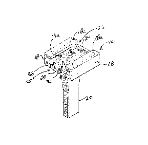
A combination slider block and pusher lug for mounting on a base plate mounted on a transfer chain includes a flanged channel having a latch and a base plate receiving cavity for snugly fitting over the base plate. A pair of flanges extend inwardly in opposed facing relation over the cavity from the sides of the channel so as to define a slot sized to receive the mount such as the weld between the base plate and the chain. The web of the flanged channel has a lug mounted orthogonally thereto. The cavity has an opening at one end, sized to receive the base plate therethrough. An opposite end of the cavity includes a stop to arrest sliding translation of the base plate through and along the cavity. The latch is mounted adjacent the opening. The latch operates to selectively lock the base plate in the cavity.


French Abstract

Une combinaison de bloc coulissant et de plaque de poussée servant à linstallation sur une plaque de base installée sur une chaîne de transfert comprend un canal bridé comportant un verrou et une plaque de base recevant une cavité en vue dun raccord serré sur la plaque de base. Une paire de brides se prolongent vers lintérieur dans une relation de face opposée sur la cavité des côtés du canal de sorte à définir une fente de taille à recevoir la partie dinstallation comme la soudure entre la plaque de base et la chaîne. La toile du canal bridé présente un ergot installé de manière orthogonale. La cavité présente, à une extrémité, une ouverture de taille à recevoir la plaque de base. Une extrémité opposée de la cavité comprend une butée servant à arrêter la translation par coulissement de la plaque de base dans la cavité et le long de la cavité. Le verrou est installé adjacent à louverture. Le verrou agit pour bloquer de manière sélective la plaque de base dans la cavité.

Claims

Note: Claims are shown in the official language in which they were submitted.


WHAT IS CLAIMED IS:
1. A combination slider block and pusher lug for mounting on a base plate
mounted
on a transfer chain wherein the base plate has a length, a width and a
thickness,
and is mounted substantially flush on the chain, and wherein a mount mounts
the
base plate to the chain, and wherein the mount is inset from the sides of the
base
plate, the combination slider block and pusher lug comprising:
a flanged channel having a base plate receiving cavity wherein opposite sides
of
said channel define said cavity, said cavity having a depth corresponding to
the
thickness of the base plate, and a width corresponding to the width of the
base
plate and which includes the sides of the base plate, and wherein a pair of
flanges
extend inwardly in opposed facing relation over said cavity from said sides of
said
channel so as to define a slot therebetween and wherein said slot is sized to
receive therein the mount between the base plate and the chain, so that when
the
base plate is mounted within said cavity, the mount mates in and along said
slot,
wherein said flanged channel has a web between said sides which covers
substantially the length and the sides of the base plate when the base plate
is
mounted in the cavity and wherein said web has a lug mounted orthogonally
thereto so as to protrude orthogonally from said web, disposed on said web
orthogonally to said cavity, wherein said cavity has an opening therein at one
end
of said flanged channel, sized to receive therethrough the base plate, and
wherein
an opposite end of said cavity, opposite to said opening, includes a stop to
arrest
sliding translation of the base plate through and along said cavity,
and wherein a latch is mounted to said flanged channel so as to be adjacent
said
opening and wherein said latch is biasable between an open position wherein
said
opening is unobstructed for receiving the base plate therethrough, and a
closed
position selectively locking the base plate into said cavity.
2. The device of claim 1 wherein said latch is resilient.
8

3. The device of claim 2 wherein said latch includes a tongue mounted to
said
flanged channel, and wherein a distal end of said tongue has a latch dog which
at
least partly occludes said opening when said latch is in said closed position.
4. The device of claim 3 wherein said tongue is mounted to said web along a
resilient hinge-line so as to provide a resilient hinge for resilient biasing
of said
latch between said open and closed positions.
5. The device of claim 4 wherein said flanged channel is resiliently
deformable.
6. The device of claim 1 wherein said flanged channel is resiliently
deformable.
7. The device of claim 4 wherein said flanged channel has at least one cut-
out and
wherein each cut-out of said at least one cut-out contains at least part of a
corresponding said tongue so that said hinge line is recessed within at least
one
said each cut-out.
8. The device of claim 7 wherein said each cut-out contains substantially
all of said
tongue.
9. The device of claim 7 wherein said at least one cut-out is in said web.
10. The device of claim 3 wherein said opposed-facing flanges define a
corresponding height of said cavity between each of said opposed-facing
flanges
and said web, and wherein said latch dog has a height which is less than said
height of said cavity , whereby a deflection distance of said tongue when
deflected into said latch open position is minimized.
11. The device of claim 10 wherein said latch dog is a lip extending across
said
tongue.
9

12. The device of claim 11 wherein said lip has a notch for the insertion
of a tool
between said tongue and said plate, whereby the tool deflects said tongue into
said
latch open position.
13. The device of claim 4 wherein said web and said tongue are
substantially planar,
and wherein said tongue is cantilevered from said web.
14. The device of claim 13 wherein said tongue and said web are
substantially co-
planar when said tongue is undeflected.
15. The device of claim 14 wherein said web has a cut-out and wherein said
cut-out
contains at least part of said tongue so that said hinge line is recessed
within said
cut-out.
16. The device of claim 15 wherein said cut-out contains substantially all
of said
tongue.
17. The device of claim 16 wherein said flanged channel is resiliently
deformable.

Description

Note: Descriptions are shown in the official language in which they were submitted.


CA 02782711 2012-07-05
COMBINATION SLIDER BLOCK AND PUSHER LUG
Field of the Invention
This invention relates to the field of pusher lug lumber conveyors
employed in the lumber industry, and in particular to an improvement to pusher
lugs and
slider blocks.
Background of the Invention
As stated by Henderson et al in United States patent No. 6,964,334 which
issued November 15, 2005, it is common practice in lumber processing
facilities such as
sawmills to transport lumber over the top of sorter bins by overhead chain
conveyors
equipped with pusher lugs. Chain conveyors for the movement of lumber have
links
which each have an upstanding lug mounted thereon, spaced at intervals along
the chain.
Movement of the chain brings the lug into contact with the lumber, which is
then urged in
the direction of the running of the chain. When the lumber is located over a
desired bin, a
gate corresponding to that bin opens allowing the lumber to fall into that
bin.
Conventionally, a slider block is rigidly mounted to the chain where the
pusher lugs
attach to the chain to facilitate sliding translation of the lugs along the
conveyor.
Typically, fasteners attach the slider block to the chain, requiring that the
chain links be
pre-drilled where the slider blocks are to be fastened. Thus, the process of
attaching the
slider blocks to the chain is time consuming and costly.
Consequently Henderson et al disclosed a slider block that required no
pre-drilling of the chain and no fasteners for mounting of the slider block
onto the chain
and pusher lug. The snap-on slider block provided for efficient installation
and
replacement of slider blocks. Henderson et al described the slider block as a
length of
resilient flanged channel having a cut-out in the lower web of the channel to
accommodate mounting a flat bar journalled in the cut-out. The flanged channel
had a
length sufficient to cover the length of a base plate on which the flat bar
was orthogonally

CA 02782711 2012-07-05
mounted. The sides of the channel defined a cavity having a depth
corresponding to the
thickness of the base plate. A pair of flanges extended inwardly over the
cavity from the
sides of the channel so as to define a chain-receiving slot therebetween. The
base plate
mounted within the cavity. The base plate was welded to a chain so that when
the base
plate was mounted in the cavity the chain was mounted in and along the chain-
receiving
slot.
In the prior art applicant is also aware of United States Patent No.
7,530,448 which issued May 12, 2009, to Henderson et al for Capped Lugs for
Transfer
Chains. Henderson et al describe each lug as having a cap defining a housing
in which
the lug is mounted, and wherein the housing is sealed around the lug to
inhibit the entry
of detritus into the housing.
A drawback of the snap-on slider block of US Patent No. 6, 964, 334 is
that the lug is metal and rigidly mounted to the chain. Thus, in the event of
jamming or
collisions of boards on the chain conveyor causing damage to the lugs,
especially if the
lugs are older and fatigued, the metal lugs will bend making them unusable.
Metal lugs
which have been bent or otherwise deformed so that they are no longer useful
must be cut
off and replaced. This typically requires that initially the lug is cut off to
leave a stub so
that a snap-on slider block may still be mounted on the base plate and the
conveyor can
then be later repaired properly to replace the stub with a full size metal
lug. The cutting
off of the damaged lug requires, at least to the extent that applicant's are
aware, a hot
work permit for the use of the torch within the mill facility and so it is
inconvenient to
effect the repair.
It is preferable that, in the event of damage, that the lugs break off rather
than deform and have to be cut off. Consequently the present invention
provides a
combination slider block and lug which snaps into place over the base plate
welded to the
transfer chain either in the case of new chains where all the slider blocks
and lugs are of
the snap-on design according to the present invention, or in the case where a
lug is
damaged, once the damaged lug has been entirely removed. In either case the
snap-on
2

CA 02782711 2012-07-05
combination slider blocks and pusher lug is intended to snap off, rather than
bend or
deform, in the event of a damage-causing event.
Summary of the Invention
In summary the combination slider block and pusher lug according to the
present invention for mounting on a base plate mounted on a transfer chain,
wherein the
base plate has a length, a width and a thickness, and is mounted substantially
flush on the
chain, and wherein a mount mounts the base plate to the chain, and wherein the
mount is
inset from the sides of the base plate, may be characterized in one aspect as
including a
flanged channel having a latch and a base plate receiving cavity wherein
opposite sides of
the channel define the cavity. The cavity has a depth corresponding to the
thickness of the
base plate, and a width corresponding to the width of the width base plate. In
particular,
the width includes the sides of the base plate. A pair of flanges extend
inwardly in
opposed facing relation over the cavity from the sides of the channel so as to
define a slot
therebetween. The slot is sized to receive therein the mount between the base
plate and
the chain, so that when the base plate is mounted within the cavity, the mount
mates in
and along the slot.
The flanged channel has a web between the sides which covers
substantially the length and the sides of the base plate when the base plate
is mounted in
the cavity. The web has a lug mounted orthogonally thereto so as to protrude
orthogonally from the web. Thus the lug is disposed on the web orthogonally to
the
cavity. The cavity has an opening therein at one end of the flanged channel,
sized to
receive therethrough the base plate. An opposite end of the cavity, opposite
to the
opening, includes a stop to arrest sliding translation of the base plate
through and along
the cavity. In operation of the transfer chain, as the lug translates and
engages a board the
stop is urged against the base plate.
The latch selectively locks the base plate in the cavity and is mounted to
the flanged channel so as to be adjacent the opening. The latch may be biased
between an
3

CA 02782711 2012-07-05
open position wherein the opening is unobstructed for receiving the base plate
therethrough, and a closed position selectively locking the base plate into
the cavity.
The latch may advantageously be resilient and may include a tongue
mounted to the flanged channel, and wherein a distal end of the tongue has a
latch dog
which at least partly occludes the opening when the latch is in the closed
position. In one
embodiment not intended to be limiting the tongue is mounted to the web along
a
resilient hinge-line so as to provide a resilient hinge for resilient biasing
of the latch
between the open and closed positions. In further embodiments the tongue is
formed as
part of the flanged channel, and the entire flanged channel is resiliently
deformable.
In one embodiment the flanged channel has at least one cut-out and each
cut-out contains at least part of a corresponding tongue so that the hinge
line is recessed
within the each cut-out. In some embodiments each cut-out contains
substantially all of
its corresponding tongue. Advantageously at least one cut-out is in the web.
In one embodiment the opposed-facing flanges define a corresponding
height of the cavity, where the height is the distance between each of the
opposed-facing
flanges and the web, and wherein the latch dog has a height which is less than
the height
of the cavity. Thus the deflection distance is minimized for the tongue to
deflect into its
latch open position.
In the illustrated embodiment, which is not intended to be limiting, the
latch dog is a lip extending across the tongue. The lip may have a notch for
the insertion
of a tool between the tongue and the plate. The tool, which may be a bladed
tool such as a
screw driver, may thus deflect the tongue into the latch open position.
In a preferred embodiment, in the latch closed position the web and the
tongue are substantially planar, the tongue is cantilevered from the web, and
the tongue
and the web are substantially co-planar when the tongue is undeflected.
4

CA 02782711 2012-07-05
In embodiments wherein the web has a cut-out and wherein the cut-out
contains at least part of or all of the tongue so that the hinge line is
recessed within the
cut-out, the tongue may be deflected so as to operate the latch while the base
plate is fully
supported within the cavity to thereby maintain the mounting of the flanged
channel on
the base plate as the tongue is levered into its open position.
Brief Description of the Drawings
FIG. 1 is a right-side perspective view of a combination slider block and
pusher lug according to one embodiment of the present invention.
FIG. 2 is a perspective view of the chain and base plate of FIG. 1.
FIG 2a is a sectional view along line 2a-2a in Figure 2.
FIG. 3 is top perspective view of a further embodiment of the pusher lug
of FIG. 1.
FIG. 4 is a bottom perspective view of the pusher lug of FIG. 3.
FIG. 5a is, in plan view, the pusher lug of FIG. 3.
FIG. 5b is, in front elevation view, the pusher lug of FIG 3.
FIG. 5c is, in right side elevation view, the pusher lug of FIG. 3.
Detailed Description Of Embodiments Of The Invention
With reference to the drawing figures wherein similar characters of
reference denote corresponding parts in each view, as seen for example in
Figures 1, 2

CA 02782711 2012-07-05
and 2a, a length of chain 10 has base plate 12 welded to it at a weld or mount
12a
between the base plate and chain, across the width "w" of chain 10.
Slider block 14 may advantageously be made of wear-resistant resilient
material such as plastic or other malleable or formable solids. In preferred
embodiments,
such as seen in Figs. 1 and 3, block 14 is a flanged channel, sleeve or
envelope
(collectively referred to as a flanged channel) so that block 14 slides snugly
over plate 12,
except for where plate 12 is welded at mount 12a to chain 10, so that the
plate is snuggly
journalled in the cavity 14a defined by the interior of the flanged channel.
The web 16
joining side walls 18 of slider block 14 has a pusher lug 20 mounted
orthogonally to it. It
is understood that a plurality of a combination of slider blocks and pusher
lugs are
mounted in spaced array along the length of the chain. Only one of the
combination slider
blocks and pusher lugs is illustrated.
Opposed facing inwardly turned flanges 18a mounted along the upper
edges of side walls 18 define a slot 22 between flanges 18a for receiving weld
or mount
12a therein as slider block 14 is slid over base plate 12 until base plate 12
abuts end wall
or stop 24.
In operation, chain 10, plates 12 and slider blocks 14 run along the inner
lowermost surfaces inside a chain run (not shown). Thus, the lower surface of
slider
block 14 may be contoured to match the contour of the inner lowermost surface
of the
chain run. Lug 20 protrudes downwardly from slider block 14 and through a slot
in the
lowermost surfaces of the chain run. As chain 10 is run in direction A along
its
longitudinal axis, slider block 14 slides along the inner surface of the chain
run, carrying
lug 20. That is, chain 10 is run in a direction such that lug 20 pushes plate
12 against the
end wall or stop 24. On an endless chain, at the end of the chain run, the
pusher lug and
slider block are returned along the corresponding chain return which may be a
chain
return channel in which chain 10 is run. Slider block 16 carries plate 12 and
lug 20 over
the upper surface of the chain return channel.
6

CA 02782711 2016-04-06
A latch 26 is provided on web 16 to hold plate 12 within the cavity 14a
defined
by the flanged channel so as substantially abut plate 12 against end wall or
stop 24. In an
alternative embodiment, not illustrated, one or more latches 26 may be
provided, which
may for example be mounted on one or both of side walls 18, whether or not in
addition
to a latch 26 being mounted on web 16. Latch 26 may, as illustrated, take the
form of a
resilient tongue 28, although this is not intended to be limiting. Tongue 28
may, as
illustrated be recessed into a cutout 16a in web 16. Thus tongue 28 may be
substantially
contained within cut-out 16a while being cantilevered from web 16 along hinge
line 30.
Thus tongue 28 may deflect resiliently in direction B about hinge line 30. In
its normal
non-resiliently biased position an upwardly extending hook, lip, dog or flange
32 on the
distal end of tongue 28 engages against the corresponding end edge of plate 12
so as to
releasably lock plate 12 into cavity 14a. Tongue 28 may be deflected
downwardly when
it is desired to remove slider block 14 and lug 20 from plate 12, for example
if lug 20
becomes damaged during use.
A notch 32a may be provided in flange 32 so that for example a lever such as a
screwdriver blade may be inserted through notch 32a and under plate 12. With
the lever
thus positioned, tongue 28 may be deflected downwardly by levering the lever
downwardly, thereby releasing latch 26 from its engagement with plate 12,
thereby
allowing slider block 14 to be slid off plate 12.
The scope of the invention is to be construed in accordance with the substance
defined by the following claims.
7

Representative Drawing
A single figure which represents the drawing illustrating the invention.
Administrative Status

2024-08-01:As part of the Next Generation Patents (NGP) transition, the Canadian Patents Database (CPD) now contains a more detailed Event History, which replicates the Event Log of our new back-office solution.

Please note that "Inactive:" events refers to events no longer in use in our new back-office solution.

For a clearer understanding of the status of the application/patent presented on this page, the site Disclaimer , as well as the definitions for Patent , Event History , Maintenance Fee  and Payment History  should be consulted.

Event History

Description Date
Inactive: Office letter 2024-06-14
Revocation of Agent Requirements Determined Compliant 2024-06-14
Appointment of Agent Requirements Determined Compliant 2024-06-14
Inactive: Office letter 2024-06-14
Revocation of Agent Request 2024-06-05
Appointment of Agent Request 2024-06-05
Inactive: Office letter 2023-08-22
Appointment of Agent Requirements Determined Compliant 2023-07-13
Revocation of Agent Request 2023-07-13
Appointment of Agent Request 2023-07-13
Revocation of Agent Request 2023-07-13
Revocation of Agent Requirements Determined Compliant 2023-07-13
Appointment of Agent Requirements Determined Compliant 2023-07-13
Revocation of Agent Requirements Determined Compliant 2023-07-13
Common Representative Appointed 2019-10-30
Grant by Issuance 2016-08-16
Inactive: Cover page published 2016-08-15
Pre-grant 2016-06-20
Inactive: Final fee received 2016-06-20
Letter Sent 2016-04-25
Notice of Allowance is Issued 2016-04-25
Inactive: Q2 passed 2016-04-18
Inactive: Approved for allowance (AFA) 2016-04-18
Amendment Received - Voluntary Amendment 2016-04-06
Letter Sent 2015-10-06
Inactive: S.30(2) Rules - Examiner requisition 2015-10-06
Reinstatement Requirements Deemed Compliant for All Abandonment Reasons 2015-10-05
Deemed Abandoned - Failure to Respond to Maintenance Fee Notice 2015-07-06
Inactive: Report - No QC 2015-07-03
Letter Sent 2014-08-14
Amendment Received - Voluntary Amendment 2014-07-31
Request for Examination Requirements Determined Compliant 2014-07-31
All Requirements for Examination Determined Compliant 2014-07-31
Request for Examination Received 2014-07-31
Inactive: Cover page published 2014-01-13
Application Published (Open to Public Inspection) 2014-01-05
Inactive: First IPC assigned 2013-01-11
Inactive: IPC assigned 2013-01-11
Application Received - Regular National 2012-07-25
Letter Sent 2012-07-25
Inactive: Filing certificate - No RFE (English) 2012-07-25
Small Entity Declaration Determined Compliant 2012-07-05

Abandonment History

Abandonment Date Reason Reinstatement Date
2015-07-06

Maintenance Fee

The last payment was received on 2016-06-28

Note : If the full payment has not been received on or before the date indicated, a further fee may be required which may be one of the following

  • the reinstatement fee;
  • the late payment fee; or
  • additional fee to reverse deemed expiry.

Patent fees are adjusted on the 1st of January every year. The amounts above are the current amounts if received by December 31 of the current year.
Please refer to the CIPO Patent Fees web page to see all current fee amounts.

Fee History

Fee Type Anniversary Year Due Date Paid Date
Registration of a document 2012-07-05
Application fee - small 2012-07-05
MF (application, 2nd anniv.) - small 02 2014-07-07 2014-07-07
Request for examination - small 2014-07-31
Reinstatement 2015-10-05
MF (application, 3rd anniv.) - small 03 2015-07-06 2015-10-05
Final fee - small 2016-06-20
MF (application, 4th anniv.) - small 04 2016-07-05 2016-06-28
MF (patent, 5th anniv.) - small 2017-07-05 2017-05-29
MF (patent, 6th anniv.) - small 2018-07-05 2018-06-04
MF (patent, 7th anniv.) - small 2019-07-05 2019-07-02
MF (patent, 8th anniv.) - small 2020-07-06 2020-06-30
MF (patent, 9th anniv.) - small 2021-07-05 2021-06-16
MF (patent, 10th anniv.) - small 2022-07-05 2022-06-10
MF (patent, 11th anniv.) - small 2023-07-05 2023-06-05
MF (patent, 12th anniv.) - small 2024-07-05 2024-05-08
Owners on Record

Note: Records showing the ownership history in alphabetical order.

Current Owners on Record
NORTHERN PLASTICS LTD.
Past Owners on Record
DEANE R. HENDERSON
Past Owners that do not appear in the "Owners on Record" listing will appear in other documentation within the application.
Documents

To view selected files, please enter reCAPTCHA code :


To view images, click a link in the Document Description column (Temporarily unavailable). To download the documents, select one or more checkboxes in the first column and then click the "Download Selected in PDF format (Zip Archive)" or the "Download Selected as Single PDF" button.

List of published and non-published patent-specific documents on the CPD .

If you have any difficulty accessing content, you can call the Client Service Centre at 1-866-997-1936 or send them an e-mail at CIPO Client Service Centre.

({010=All Documents, 020=As Filed, 030=As Open to Public Inspection, 040=At Issuance, 050=Examination, 060=Incoming Correspondence, 070=Miscellaneous, 080=Outgoing Correspondence, 090=Payment})


Document
Description 
Date
(yyyy-mm-dd) 
Number of pages   Size of Image (KB) 
Description 2012-07-04 7 312
Claims 2012-07-04 3 99
Abstract 2012-07-04 1 20
Drawings 2012-07-04 5 75
Representative drawing 2013-12-09 1 11
Description 2016-04-05 7 302
Claims 2016-04-05 3 97
Representative drawing 2016-07-06 1 9
Maintenance fee payment 2024-05-07 1 25
Change of agent 2024-06-04 4 116
Courtesy - Office Letter 2024-06-13 2 195
Courtesy - Office Letter 2024-06-13 2 199
Courtesy - Certificate of registration (related document(s)) 2012-07-24 1 125
Filing Certificate (English) 2012-07-24 1 166
Reminder of maintenance fee due 2014-03-05 1 113
Acknowledgement of Request for Examination 2014-08-13 1 176
Courtesy - Abandonment Letter (Maintenance Fee) 2015-08-30 1 172
Notice of Reinstatement 2015-10-05 1 163
Commissioner's Notice - Application Found Allowable 2016-04-24 1 161
Maintenance fee payment 2023-06-04 1 25
Fees 2014-07-06 1 23
Fees 2015-10-04 1 26
Examiner Requisition 2015-10-05 4 206
Amendment / response to report 2016-04-05 11 318
Final fee 2016-06-19 1 35
Fees 2016-06-27 1 25
Maintenance fee payment 2017-05-28 1 24
Maintenance fee payment 2018-06-03 1 24
Maintenance fee payment 2019-07-01 1 24
Maintenance fee payment 2020-06-29 1 25
Maintenance fee payment 2021-06-15 1 25
Maintenance fee payment 2022-06-09 1 25