Note: Descriptions are shown in the official language in which they were submitted.
:A 02782787 2012-08-04
WO 2011/071794
PCT/US2010/059035
PHOTOALIGNMENT MATERIALS HAVING IMPROVED ADHESION
BACKGROUND
[0001] The present disclosure relates to new (co)polymeric materials
suitable for use as
photoalignment layers. The new photoalignment materials comprise a photo-
orientable structurally
anisotropic polymer network that displays improved adhesion to substrate
surfaces and can align thicker
monomeric and polymeric liquid crystal layers. Methods of making and applying
the new photoalignment
materials are also disclosed.
[0002] Liquid crystal materials are used in a variety of applications where
the liquid crystal material is
deposited as a layer on the surface of a substrate. The successful functioning
of a liquid crystal device
depends, at least in part, on the ability of the liquid crystal molecules
within the layer to adopt and maintain
a particular alignment or orientation. These liquid crystal layers may be
aligned or oriented using various
methods. One approach is to coat the surface of the substrate with an
orienting layer prior to the application
of the liquid crystal layer. The orienting layer may then be used to orient
the liquid crystal material on the
substrate, for example, by rubbing or irradiation with polarized
electromagnetic radiation. The orientation
layer defines the direction of orientation of the liquid crystal molecules of
the layer with the result that the
longitudinal axes of the molecules become aligned with the direction of
orientation defined by the
orientation layer. In addition to directional alignment, the orientation layer
may also impart an angle of tilt
to the liquid crystal molecules, so that the molecules align themselves at an
angle to the surface of the
orientation layer rather than lying parallel to the surface.
100031 Orientation of' polymer layers by irradiation with polarized
electromagnetic radiation has been
known. Irradiation based orientation overcomes certain drawbacks associated
with orientation by uniaxial
rubbing, such as, for example, dust generation, heat generation, destruction
of thin films, and lack of
structuring capability. Further, orientation by irradiation also allows for
the possibility to provide distinct
areas having different orientation relative to neighboring areas. Examples of
photo-orientable alignment
materials include polymer-bonded photoactive cinnamic acid derivatives,
coumarin derivatives, cis/trans
isomerizable azo derivatives, and photochemically decomposable polyhnide
derivatives.
[0004] United States Patent No, 6,107,427 is directed to cross-linkable
photoactive polymeric
materials comprised of 3-myl-acrylic acid esters and amides as well as to
their use as orienting layers for
liquid crystal layers. Such materials find use in the production of optical
elements and multi-layer systems,
such as liquid crystal displays.
100051 International Publication No. WO 2004/060861 A2 discloses a photo-
crosslinkable copolymers
of (a) at least one monomer from the group of acrylates, methacrylates,
acrylamides and inethaerylamides
to each of which is covalently bonded, directly or via a bridging group, a
photochemically isomerizable or
dimerizable molecule, (b) at least one polyoxyalkyl ester or one
polyoxyalkylamide of an ethylenically
unsaturated monomer or dicarboxylic acid, or one polyoxyalkyl ether of an
ethylenically unsaturated
-1
:A 02782787 2012-08-04
WO 2011/071794
PCT/US2010/059035
alcohol, and (c) optionally, other ethylenically unsaturated comonomers. The
copolymers have a glass
transition temperature of not more than 70 C, and preferably less. Such
materials are suitable as alignment
layers for liquid crystals used in the production of electrooptical elements,
e.g., liquid crystal displays,
compensation films optical delay filters, eholesterie filters, antireflection
filters and the like.
[0006] International Publication No. WO 2005/015298 Al provides an
alignment layer having
improved adhesion to liquid crystal films, to a precursor material used for
the preparation of such a layer, to
a laminate comprised of such a layer and at least one liquid crystal polymeric
film, and to the use of the
alignment layer and the laminate for optical, electro-optical, decorative or
security uses and devices. The
alignment layer and the precursor material comprise at least one reactive
mesogen in monomeric,
oligomerie or polymeric form. The reactive mesogen preferably are incorporated
into the solvated
composition used to form an alignment film. Alternately the reactive mesogen
can be used as a component
in a composition used to form a command layers which generally are not polymer
layers, but self-
assembled monolayers or multilayers. The promotion of liquid crystal alignment
by the command layer
generally is not a bulk effect, but rather a surface effect where the command
layer molecules are tethered to
the surface, and typically are only a monolayer thick.
[0007] While the aforementioned photo-aligning copolymers and the resulting
alignment layers exhibit
somewhat improved adhesion (to substrates to which they are applied and to the
subsequently applied
liquid crystal layers), they nevertheless do not provide sufficient adhesion
to either layer for some
applications, for example for use in the production of ophthalmic devices such
as lenses. These prior art
alignment layer materials used in liquid crystal devices still generally
demonstrate poor adhesion for such
applications, and often are produced using high processing temperatures (200 C
to 250QC) that are not
compatible for certain substrates, e.g., plastic optical substrates As
previously mentioned, adhesion
between layers in applications where a liquid crystal layer or other layer is
deposited on the surface of the
photoalignment layer is also necessary. In applications where adhesion levels
are not sufficient, peeling of
the photoalignment layer from the substrate surface and/or peeling of
subsequent layers from the surface of
the photoalignment layer may be observed.
[0008] Further, certain applications, such as ophthalmic applications,
utilize liquid crystal layers of
greater than 20 microns in thickness. In these applications, photoalignment
layers that are capable of
aligning adherent liquid crystal layers of up to 1,000 microns in thickness
are desired. Thus,
photoalignment materials that may be used to form layers having improved
adhesion properties and thicker
aligned liquid crystal layers, relative to known photoalignment materials, are
desired. The photoalignment
materials of the present invention overcome the shortcomings of the previously
known photo-aligning
copolymers and alignment layers comprising them, and provide the desired
improved adhesion properties.
BRIEF SUMMARY OF THE DISCLOSURE
[0009] The present disclosure relates to a (co)polymer comprising:
a structure represented by the formula:
-2-
:A 02782787 2012-08-04
WO 2011/071794
PCT/US2010/059035
___________________________ L _______________ -Li!' 1 z
= [ -x
L a Lb LC
1
Za ZI) Z c
where:
each M1, Mb, and Mc are each independently residues of monomeric units
selected from
substituted or unsubstituted acryloyl units, wherein said acryloyl
substituents are chosen
from CI-CI alkyl, phenyl, -O. and combinations thereof, , substituted or
unsubstituted
styrene units, substituted or unsubstitutal epoxy units, substituted or
unsubstituted urethane
units, substituted or unsubstituted polycarboxylic acid, substituted or
unsubstituted polyol
units, substituted or unsubstituted polyatnine units, or substituted or
unsubstituted
hydroxyalkanoic acid units; wherein said substituents are selected from C1-C20
alkyl, C--
C20 alkoxy, C3-00 cycloalkyl, C1-C20 alkyl(C1-C20)alkoxy, halo(Ci-C20)alkyl,
heterocyclo(C3-Cio )alkyl, haloaryl, halo(Ci-C20)alkylaryl, CI-Cm alkylaryl,
C1-C20
alkoxyaryl, heteroaryl, aryl(Ci-C20)alkyl, heteroaryl(Ci-C20)alkyl;
1,, Lb, and 1_,0 are spacer groups that are each independently selected from a
single bond, -
(CF2)h-, -Si(Z')2(CH2)g-, or -(SI(CH3)20)1,-, -N(R)-, -C(R)=C(R)-, -C(R)=N-, -
C(R')2-C(R8)2-, -0-, -
C(0)-, -CC-, -S-, -S(0)-, -S(0)(0)-, -(0)8(0)0-, -0(0)S(0)0-, straight-
chain or
branched C1-C4 alkylene residue, arylene, C3-C10 cycloalkylene, or various
combinations thereof;
wherein Z' is independently chosen for each occurrence from hydrogen, C1-
C1salkyl, C3-C10
cycloalkyl or aryl; R is independently chosen for each occurrence from Zb,
hydrogen, CI-Cig alkyl,
C3-C10 cycloalkyl or aryl; R' is independently chosen for each occurrence from
Zb, C1-Ci8 alkyl, C3-
Ci0 cycloalkyl or aryl; the CI-Cm alkylene residue is mono-substituted by Zb,
cyano, or halo, or
poly-substituted by Zb or halo; "g" is independently chosen for each
occurrence from 1 to 20, and
"h" is a whole number from 1 to 16 inclusive;
each Za is independently a photochemically active chromophore selected from a
dimerizable substituted or unsubstituted cinnamate or substituted or
unsubstituted
coumarin, a cis/trans isomerizable substituted or unsubstituted azo, a
photochemically
decomposable substituted or unsubstituted polyimide, or a substituted or
unsubstituted
aromatic ester capable of undergoing a Photo-Fries rearrangement;
each Z1' is an adhesion promoter group independently selected from hydroxy,
carboxylic acid,
anhydride, isocyanato, blocked isocyanato, thioisocyanato, blocked
thloisoeyanato, amino, thio,
organofunctional silane, organofunctional titanate, organofunctional
zirconate, or epoxy, wherein
each organofunctional group is independently selected from vinyl, allyl, vinyl-
functional
-3-
:A 02782787 2012-08-04
WO 2011/071794
PCT/US2010/059035
hydrocarbon radicals, epoxy-functional hydrocarbon radicals, al lyl-functional
hydrocarbon
radicals, acryloyl-functional hydrocarbon radicals, methacryloyl -functional
hydrocarbon
radicals, styryl-functional hydrocarbon radicals, mercapto-functional
hydrocarbon radicals
or combinations of such organofunctional groups, said hydrocarbon radicals
being selected
from Ci-C20 alkyl, C2-C20 alkenyl, C2-C20 alkynyl, CI-C20 alkoxy, C1-C20
alkyl(C1-C20)alkoxy,
C20 alkoxy(CI-C20)alkyl, aryl, heteroaryl, and combinations of such
hydrocarbon radicals;
provided that when Zb is hydroxy or carboxylic acid, the (co)polymer further
comprises at least one
other adhesion promoter group;
Z' is a mesogen structure selected from a rigid straight rod-like liquid
crystal group, a rigid bent
rod-like liquid crystal group, or a rigid disc-like liquid crystal group; and
"x" has a value of 0<x<1, "y" has a value of 0<y<1, and "z" bas a value of
0<z<1 where x y + z
= 1 and "n" has a value ranging from 10 to 10,000,
wherein when x 1, then at least one of L' and Z' is further substituted with
at least one Zb
adhesion promoter group and when y 0, then at least one of La, Za, L0 and Ze
is further substituted
with at least one Zb adhesion promoter group.
[0010] According to one embodiment, the present disclosure provides a
(co)polymer wherein z is 0.
[0011] In another
embodiment, the present disclosure provides for a (co)polymer wherein z is
greater
than 0.
[001] Further
embodiments of the present disclosure provide for articles of manufacture. The
articles
of manufacture comprise at least one photoalignable portion comprising a
(co)polymer having a structure
represented by the above Formula, wherein the variables Ma, Mb, M`, L6, Lb,
Z8, Zb, Z0, x, y, z, and n are
as described herein.
[0013] Still
other embodiments of the present disclosure provide for optical elements, such
as
ophthalmic elements, display elements, windows, mirrors, active liquid crystal
elements, or passive liquid
crystal elements. The optical elements comprise a substrate and a first at
least partial layer on at least a
portion of a surface of the substrate. The at least partial layer comprises a
(co)polymeric material having a
structure represented by the above Formula, wherein the variables Ma, Mb, M0,
La, Lb, Z', Zb, Ze, x, y, z,
and n are as set forth in detail herein. In specific embodiments, the optical
elements may further comprise
one or more additional at least partial layers on at least a portion of the
surface of the substrate.
[0014] Still
further embodiments of the present disclosure provide for a liquid crystal
cell. The liquid
crystal cell comprises a first surface, a second surface opposite the first
surface, a first at least partial layer
on at least a portion of the first surface facing the second surface, a second
at least partial layer on at least a
portion of the second surface facing the first surface, where the first at
least partial layer and the second at
least partial layer define a space, and a liquid crystal material in the space
between the first at least partial
layer and the second at least partial layer. The first at least partial layer
and the second at least partial layer
are alignment layers and at least one of the first at least partial layer and
the second at least partial layer
comprises a (co)polymer having a structure represented by the above Formula,
wherein the variables IV18,
-4-
:A 02782787 2012-08-04
WO 2011/071794
PCT/US2010/059035
Mb, Mc, L0, Lb, Lc, Za, Zb, Zc, x, y, z, and n are as set forth in detail
herein. In specific embodiments, the
liquid crystal material comprises at least one of a clichroie material or a
photochromic-dichroic material.
[0015] Still other embodiments of the present disclosure provide methods of
applying a
photoalignment material to an optical element. The method comprises applying
an at least partial layer of a
photoalignment (co)polymer material onto at least a portion of a surface of a
substrate, forming an attractive
bond between one or more adhesion promoter groups on the photoalignment
(co)polymer material and a
compatible group on the surface of the substrate, and at least partially
aligning at least a first portion of the
photoalignment (co)polymer material by exposing the at least partial layer to
polarized UV radiation. The
photoalignment(co)polymer material has a structure represented by the above
Formula, wherein the
variables M0, Mb, M0, L8, 0,1,6, Z6, Zb, Z6, x, y, z, and n are as set forth
in detail herein.
BRIEF DESCRIPTION OF THE SEVERAL VIEWS OF THE DRAWING(S)
[0016] Various embodiments disclosed herein will be better understood when
read in conjunction with
the drawings, in which:
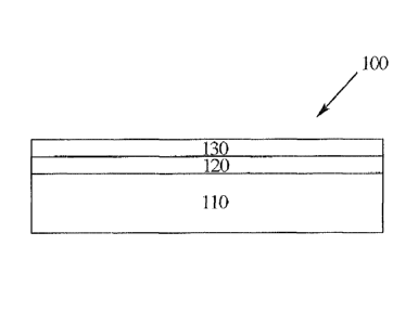
Figure 1 illustrates one embodiment of an optical element according to the
present disclosure.
Figure 2 illustrates a second embodiment of an optical element according to
the present
disclosure.
Figure 3 illustrates one embodiment of a liquid crystal cell according to the
present disclosure,
DETAILED DESCRIPTION
[0017] The present disclosure relates to structures and methods for
producing new photo-oriented
structurally anisotropic polymer networks suitable for deposition as layers on
substrates and which can
align thicker monomeric and polymeric liquid crystal layers and display
improved adherence to commonly
used substrates as well as subsequent layers deposited on the surface of the
polymer layer,
[00181 Liquid crystal materials are utilized in a variety of applications.
The molecules of a liquid
crystal ("LC") tend to align with one another in a preferred direction,
yielding a fluid material with
anisotropic optical, electromagnetic, and/or mechanical properties. The
rnesogen is the fundamental unit of
an LC, which induces the structural order in the liquid crystal material. The
mesogenic moiety of the LC
typically comprises a rigid moiety which aligns with other mesogenie
components in the LC composition,
thereby aligning the LC molecules in one specific direction, The rigid portion
of the mesogen may consist
of a rigid molecular structure, such as a mono- or polycyclic ring structure,
including for example, a mono-
or polycyclie aromatic ring structure. Liquid crystals mesogens that are
suitable for use in conjunction with
various embodiments disclosed herein include thermotropic liquid crystal
mesogens and lyotropic liquid
crystal mesogens. Examples of thermotropic liquid crystal mesogens that are
suitable for use in
conjunction with various embodiments disclosed herein include columatio (or
rod-like) liquid crystal
mesogens, discotic (or disc-like) liquid crystal mesogens, and cholesteric
liquid crystal mesogens.
Examples of potential mesogens are set forth in greater detail, for example,
in U.S. Application Serial No.
-5-
:A 02782787 2012-08-04
WO 2011/071794
PCT/US2010/059035
12/163,116, at paragraphs 100241400471; and include those described in Demus,
et al., "Fltissige Kristalle
in Tabellen," VEB Deutsche]. Verlag Fur Grundstoftindustrie, Leipzig, Germany,
1974 and "Fltissige
Kristalle in Tabellen II," VEB Deutscher Verlag Ftir Grundstoffindustrie,
Leipzig, Germany, 1984.
[0019] LCs may exist in a non-ordered state or an ordered (aligned) state.
The LC molecules in the
non-ordered state will adopt an essentially random orientation, that is, there
will be no general orientation to
the LC molecules. The LC molecules in an ordered or aligned state will
generally adopt an orientation
where the inesogenic portions of the LC molecules are at least partially
aligned throughout the aligned
portion of the LC material, As used herein, the terms "align" or "aligned"
mean to bring into suitable
arrangement or position by interaction with another material, compound or
structure, In certain cases, the
mesogenie portions of the LC molecules will be at least partially aligned in a
parallel orientation. In other
cases, the mesogenic portions of the LC molecules may be at least partially
aligned in a helical orientation.
[0020] Liquid crystal polymers ("LCPs") are polymers capable of forming
regions of highly ordered
structure while in a liquid phase. LCPs may be made from liquid crystal
monomer ("LCMs") compounds
that are then polymerized to form the LCP. Alternatively, LCPs may be formed
by polymerizing a
polymerizable material in the presence of a liquid crystal material, such that
the liquid crystal material in
entrapped in the polymer. LCs, LCMs, and LCPs have a wide range of uses,
ranging from use as strong
engineering plastics to delicate gels for LC displays. These materials may
also be used, for example, in
optical elements, such as, ophthalmic elements, display elements, windows, and
mirrors. Liquid crystal
materials may be used, for example, as at least partial layers, coatings, or
films on at least a portion of a
substrate and may impart certain desired characteristics to the substrate,
such as, for use in optical data
storage applications as photomasks or decorative pigments; in cosmetics and
for security applications (see,
for example, U.S. Patent No. 6,217,948); as curable resins for medical,
dental, adhesive and
stereolithographic applications (see, for example, U.S. Patent No. 7,238,831);
as articles of manufacture,
such as, molded assemble, or cast articles for use in the aforementioned
applications and various related
devices. In certain cases, the LC materials may be incorporated into optical
elements, such as, for example,
ophthalmic elements, display elements, windows, mirrors, active and passive
liquid crystal cells, elements,
and devices and other LC or LCP containing articles of interest, such as,
polarizers, optical compensators
(see, for example, U.S. Patent No. 7,169,448), optical retarders (see, for
example, U.S. Patent No.
RE39,605E), color filters, and waveplates for lightwave circuits (see, for
example, U.S. Patent No.
7,058,249), Certain mesogenic compounds may find particular use as LCMs and
LCPs for the formation of
ophthalmic elements which further comprise a dichroic or photochromie-dichroic
material or compound.
Dichroic compounds are capable of preferentially absorbing one of two
orthogonal components of plane
polarized light.
[0021] It is generally necessary to suitably position or arrange the
mesogenic or LC molecules,
including, for example, dichroie compounds, in order to achieve the desired
effect. That is, for rod-like or
linear mesogens, it is generally necessary to at least partially align the
molecules of the compound such that
the long axes of the at least partially aligned molecules of the mesogenic
compound are generally parallel to
-6-
:A 02782787 2012-08-04
WO 2011/071794
PCT/US2010/059035
each other, At least partial alignment of LC materials or other anisotropic
materials may be effected by at
least one of exposing the at least a portion of the material to a magnetic
field, exposing the at least a portion
of the material to a shear force, exposing the at least a portion of the
material to an electric field, exposing
the at least a portion of the material to plane-polarized ultraviolet (UV)
radiation, exposing the at least a
portion of the material to infrared radiation, drying the at least a portion
of the material, etching the at least
a portion of the material, rubbing the at least a portion of the material, and
aligning the at least a portion of
the material with another structure or material, such as an at least partially
ordered alignment material, It is
also possible to align the LC materials or other anisotropic material with an
oriented surface, such as a
surface coated with an at least partially ordered alignment material. That is,
liquid crystal molecules can be
applied as a coating, layer, or film to a surface that has been oriented, for
example by rubbing, grooving, or
photo-alignment methods, and subsequently aligned such that the long axis of
each of the liquid crystal
molecules takes on an orientation that is generally parallel to the general
direction of orientation of the
surface.
[0022] Alignment materials, such as photoalignment material, may be used as
a coating on a surface of
a substrate or a portion of the surface where the alignment material may be at
least partially aligned and
then may then be used to align one or more liquid crystal material in a
subsequent layer that is applied on a
portion of the alignment material layer. However, conventional photoalignment
materials may display
unsatisfactory adhesion to the surface and/or subsequent layers that may be
coated on the surface of the
photoalignment materials. This may lead to peeling or detaching of the
photoalignment layer from the
surface and/or subsequent layers and overall loss in product utility and
lifetime. The various embodiments
of the present disclosure provide for new (co)polymeric photoalignment
materials. The (co)polymeric
photoalignment materials display improved adhesion to a surface of a substrate
onto which the materials are
coated and improved adhesion between the materials and a subsequent layer that
is deposited on the surface
of the photoalignment materials layer. Improved adhesion characteristics are
affected by the incorporation
of an adhesion promoter group within the (co)polymeric structure of the
photoalignment material,
[0023] According to one embodiment, the present disclosure provides a
(co)polymer comprising a
structure represented by Formula I.
_________________________ ma
____________________________________ Mb
Y I
La Lb
za Zb
(I)
Referring to Formula!, IVI7 and Mb represent residues of monomeric units. Each
Ma and Mb are selected
from substituted or unsubstituted aeryloyl units, wherein said aeryloyl
substituents are chosen from
C1-C4 alkyl, phenyl, -0- and combinations thereof. Examples of such aeryloyl
units include
-7-
:A 02782787 2012-08-04
WO 2011/071794
PCT/US2010/059035
acryloyloxy, incthacryloyloxy and cinnamate. Each Ma and Mb are also selected
from substituted
or unsubstituted styrene units, substituted or unsubstituted epoxy units,
substituted or unsubstituted
urethane units, substituted or unsubstituted polycarboxylic acid, substituted
or unsubstituted polyol
units, substituted or unsubstituted polyamine units, or substituted or
unsubstituted hydroxyalkanoic
acid units wherein said substituents are chosen from C1-C20 alkyl, C1-C20
alkoxy, C3-C10
cycloalkyl, C1-C20 alkyl(C1-C20)alkoxy, halo(C1-C20)alkyl, heterocyclo(C3-Clo
)alkyl, haloaryl,
halo(C1-C20)alky/aryl, C1 -C20 alkylaryl, CI-Cm allcoxyaryl, lictcroaryl,
aryl(CI-C20)alkyl and
heteroaryl(Ci -C20)alkyl. As used herein, the term "residues" when used in
reference to a monomer or
monomeric unit means that which remains of the monomeric unit after it has
been incorporated into a
polymer chain. As used herein, the term "derivative" when used in reference to
a carboxylic acid or
polycarboxylic acid includes amides, esters, acyl halides, acyl anhydrides,
and cyano derivatives. The M6
and Mb groups in Formula I make up the polymer main chain of the (co)polymer.
According to specific
embodiments, the M6 arid Mb groups may each independently be residues of
substituted or unsubstituted
acryloyloxy units or substituted or unsubstituted inathacryloyloxy units.
[00241 As
represented by Formula I, the (co)polymer has pendant groups ¨1!-Z0 and ¨Lb-
Zb, where
the L groups represent spacer groups between the monomeric residue (i.e., Ma
and Mb) and the Za and Zb
groups, According to various embodiments, the L' and Lb groups are spacer
groups that may each
independently selected from a single bond, -(CH2)g-, -(CF2)ii-, -Si(Z')2(CH2)5-
, or -(Si(CH3)20)h-, -N(R)-, -
C(R)=C(R)-, -C(R)=N-, -C(R12-C(R')2-, -0-, -C(0)-, -S-, -
S(0)-, -S(0)(0)-, -(0)S(0)0-,
-0(0)S(0)0-, straight-chain or branched Cm-C2,1 alkylene residue, arylene, C3-
C10 cycloalkylene, or various
combinations thereof'. According to these structures, Z' may be independently
chosen for each occurrence
from hydrogen, CI-C ig alkyl, C3-00cycloalkyl or aryl; R may be independently
chosen for each occurrence
from Zb, hydrogen, CI-Cis alkyl, C3-C10 cycloalkyl or aryl; R' may
independently chosen for each
occurrence from Zb, Ca-C12 alkyl, C3-C10 cycloalkyl or aiy1; the CI-C24
alkylene residue may be mono-
substituted by Zb, cyano, or halo, or poly-substituted by Zb or halo. Further,
according to the spacer groups
L' and Lb, "g" may be independently chosen for each occurrence from 1 to 20,
for example, from 2 to 15
or from 5 to 10; and "h" may be represented by a whole number from 1 to 16
inclusive, for example,
from 2 to 12 or from 4 to 10.
[0025] Each Za
group represents a photochemically active chromophore. As used herein, the
phrase
"photochemically active chromophore" includes structures or portions of the
molecule or polymer which
chemically react (such as with themselves or with another active moiety, for
example another
photochemically active chromophore) upon the absorption of actinic radiation.
As used herein, the term
"actinic radiation" means electromagnetic radiation that is capable of causing
a response. Actinic radiation
includes, for example visible and ultraviolet radiation. The photochernically
active chromophore may
undergo a photochemical cis/trans-isomerization, a photochemical [2+2]
cycloaddition (leading to a cross-
linking of the polymer or oligoiner), a photochemical decomposition or a
photochemical rearrangement.
-8-
CA 02782787 2015-03-25
According to various embodiments, suitable photochemically active chromophores
include
dimerizable substituted or unsubstituted cinnamate or dimerizable substituted
or unsubstituted
coumarin derivatives, cis/trans isomerizable substituted or unsubstituted azo,
photochemically
decomposable substituted or unsubstituted polyimides, and photochemically
remangeable
substituted or unsubstituted aromatic esters, such as those that can undergo a
Photo-Fries
rearrangement. In specific embodiments, the photochemically active chromophore
may be a
dimerizable substituted or unsubstituted cinnamate or a dimerizable
substituted or unsubstituted
coumarin. Cinnamates and coumarins may react upon exposure to actinic
radiation to undergo a [2+2]
dimerization as described in "Alignment Technologies and Applications of
Liquid Crystal Devices,"
Kohki Takotah et al., Taylor and Francis, New York, 2005, pages 61-63.
Examples of suitable
cinnamates may be found in U.S. Patent Nos. 5,637,739 at column 6, lines 19 to
32 and 7,173,114 at
column 3, line 13 to column 5, line 2 and coumarins may be found in U.S.
Patent Nos. 5,231,194 at
column 1, line 37 to column 3, line 50; 5,247,099 at column 1, line 66 to
column 4 line 28; 5,300,656
at column 1, line 13 to column 10, line 15; and 5,342,970 at column 1, line 6
to column 7, line 34.
[0026] Further examples of photochemically active chromophores may include:
a
photoisomerizable azo compound such as Poly ((n-butyl methacrylate-co-(E)-4-
(phenyldiazenyl)phenyl methacrylate)-b-styrene) described in Chih-Feng Huang,
Wei Chen, Thomas
P. Russell, Anna C. Balazs, Feng-Chih Chang, and Krzysztof Matyjaszewski
(2009) Macromolecular
Chemistry and Physics. "Synthesis of Photoisomerizable Block Copolymers by
Atom Transfer Radical
Polymerization". 210. Pages 1484-1492; photodegradable polyimides such as Poly
(2-methy1-6-(4-(p-
tolyloxy)phenyl)pyrrolo[3,4-f]isoindole-1,3,5,7(2H,6H)-tetraone), Poly (5-(2-
(1,3-dioxo-2-(4-(p-
tolyloxy)phenyl)isoindolin-5-y1)-1,1,1,3,3,3-hexafluoropropan-2-y1)-2-
methylisoindoline-1,3-dione),
Poly (5-(2-(1,3-dioxo-2-(4-(2-(p-tolyl)propan-2-yl)phenyl)isoindolin-5-y1)-
1,1,1,3,3,3-
hexafluoropropan-2-y1)-2-methylisoindoline-1,3-dione); and Poly (5-
(1,1,1,3,3,3-hexafluoro-2-(2-(4-
(1,1,1,3,3,3-hexafluoro-2-(p-tolyl)propan-2-yl)pheny1)-1,3-dioxoisoindolin-5-
yl)propan-2-y1)-2-
methylisoindoline-1,3-dione) described in David Creed, Charles E. Hoyle,
Pethaman Subramanian,
Rajamani Nagarajan, Chandra Pandey, Edgardo T. Anzures, Kevin M. Cane, and
Patrick E. Cassidy,
"Photodegradation of Polyirnides.6.Effect of Donor-acceptor Groups on the
Photooxidative Stability
of Polyimides and Model Compounds" Macromolecules, 1994 ,27 (3), pp. 832-837;
a photoreactive
polyimide such as (2E,2'E)-4-(5-(1,1,1,3,3,3-hexafluoro-2-(2-methy1-1,3-
dioxoisoindolin-5-yl)propan-
2-y1)-1,3-dioxoisoindolin-2-y1)-4'-methy141,11-biphenyl]-3,31-diy1 bis(3-
phenylacrylate) described in
Seung Woo Lee, Sang 11 Kim, Byeongdu Lee, Wooyoung Choi, Boknam Chae, Seung
Bin Kim, and
-9-
CA 02782787 2015-03-25
Moonhor Ree (2003) Macromolecules "Photoreactions and Photoinduced Molecular
Orientations of
Films of a Photoreactive Polyimide and Their Alignment of Liquid Crystals".
36. 6527-6536; a
photodecomposable polyimide such as
7-methy1-2-(4-(4-methylbenzyl)phenyl)tetrahydro-1H-5,9-methanopyrido[3,4-
djazepine-
1,3,6,8(2H,4H,7H)-tetraone and 2-methy1-5-(4-(4-(2-(4-(p-
tolyloxy)phenyl)propan-2-
yl)phenoxy)phenyl)hexahydrocyclobuta[1,2-c:3,4-0dipyrrole-1,3(2H,3aH)-dione
described in the The Liquid Crystal Book Series: Alignment Technologies and
Application of Liquid
Crystal Devices, by K. Takatoh et.al., 2005, Taylor and Francis, page 63; and
aromatic esters capable
of undergoing a Photo-Fries rearrangement include: Poly (5-
methacrylamidonaphthalen-1-y1
methacrylate); Poly (4-methacrylamidonaphthalen-l-ylmethacrylate); Poly (4-
methacrylamidophenyl
methacrylate); Poly (4-methacrylamidophenethyl methacrylate); and Poly (4-(2-
methacrylamidoethyl)phenyl methacrylate) described in L. Vretika, V.
Syromyatnikov, V. Zagniy, L.
Paskal, 0. Yaroshchuk, L. Dolgov, V. Kyrychenko & C.-D. Lee (2007) Molecular
Crystals and Liquid
Crystals "Polymethacryloylaminoarylmethacrylates: New Concept of
Photoalignment Materials for
Liquid Crystals"479. 121-134.
-9a-
:A 02782787 2012-08-04
WO 2011/071794
PCT/US2010/059035
[0027] Each Zb group represents an adhesion promoter group. As used herein,
the term "adhesion
promoter" means a group or structure that improves adhesion between the
(co)polymeric structure and the
substrate to which it is coated onto or to polymeric films that are coated
onto the surface of the polymer
containing the adhesion promoter. Adhesion promoters may act by forming an at
least partial attractive
force on a molecular or atomic level between the (co)polymer and the substrate
or subsequent coating.
Examples of attractive forces include covalent bonds, polar covalent bonds,
ionic bonds, hydrogen bonds,
electrostatic attractions, hydrophobic interactions, and van der Waals
attractions. That is, a functionality on
the adhesion promoter group Zh can form an attractive interaction with a
functionality on the surface or a
functionality on the subsequent coating. Within the structure of the copolymer
according to the various
embodiments herein, the attractive interaction between a plurality of adhesion
promoter groups Z and the
substrate surface or subsequent coating material results in an improved
adhesion between the copolymer
and the substrate surface and/or the subsequent coating. Various embodiments
of suitable structures for
adhesion promoter group e include hydroxy, carboxylic acid, anhydride,
isocyanato, blocked isocyanato,
thioisoeyanato, blocked thioisocyanato, amino, thio, organofunctional silane,
organofunctional titanate,
organofunctional zirconate, and epoxy, wherein each organofunctional group is
independently
selected from vinyl, ally!, vinyl-functional hydrocarbon radicals, epoxy-
functional hydrocarbon
radicals, allyl-functional hydrocarbon radicals, acryloyl-functional
hydrocarbon radicals,
methaeryloy 1-fu ncti ona I hydrocarbon radicals, styryl -fu ncti anal
hydrocarbon radicals, m ercapto-
functional hydrocarbon radicals or combinations of such organofunctional
groups, said
hydrocarbon radicals being selected from C1-C20 alkyl, C2-C20 alkenyl, C2-C20
alkynyl, Ci-C20 alkoxy,
C1-C20 alkyl(Ci-C20)alkoxy, C1-C20 alkoxy(C1-C20)alkyl, aryl, heteroaryl, and
combinations of such
hydrocarbon radicals; provided that when Zb is hyclroxy or carboxylic acid,
the (eo)polymer further
comprises at least one other adhesion promoter group; such as those promoters
disclosed in U.S. Patent
Nos. 6,025,026 at column 6, line 5 to column 8, line 65; 6,150,430 at column
2, line 59 to column 5, line
44; and 7,410,691 at column 6, line 4 to column 8, line 19. As used herein,
the term "blocked" when used
in reference to isocyanato or thioisoeyanato groups refers to a structure
where the isocyanato or
thioisocyanato group has been reversibly reacted with a group to protect the
isocyanato or thioisocyanato
group from reacting until the blocking group is removed. Generally, compounds
used to block isocyanato
or thioisocyanato groups may be organic compounds that have active hydrogen
atoms, for example volatile
alcohols, epsilon-caprolactain or ketoxime compounds. Examples of blocking
groups include amines,
hydrooxamic esters, substituted or unsubstituted pyrazol groups, phenols,
cresol, nonylphenol, caprolactam,
triazole, imidazoline, oxime, formate and diacetone, including those described
in X. Tassel et al., "A New
Blocking Agent of Isocyanates" European Polymer Journal, 2000, 36, 1745-1751
and Z. W. Wicks Jr.,
Progress in Organic Coatings, 1975, 3, 73-99.
[00281 Referring still to Formula 1, according to various embodiments, "n"
may have a value ranging
from 10 to 10,000, for example, from 100 to 5,000 or from 500 to 2,000.
According to specific
embodiments, "x" may have a value of 0 < x < 1 and "y" may have a value of 0<
y < 1, where x y = 1.
-10-
:A 02782787 2012-08-04
WO 2011/071794
PCT/US2010/059035
That is, according to these specific embodiments, the (co)polymer contains
only NI' and Mb monomer
residues, In other embodiments, such as described herein, the (co)polymer may
comprise additional
monomer residues. In those embodiments where x = I (i.e., when y = 0), then at
least one of L' and V is
further substituted with at least one Zb adhesion promoter group.
[0029] In still other embodiments of the (co)polymer described herein, the
copolymer structure
represented by Formula I may further comprise residues of a substituted
monomeric unit 1V10 having the
structure:
me
LC
Z'
where each NI may independently be a residue of monomeric unties selected from
substituted or
unsubstituted acryloyl units, wherein said acryloyl substituents are chosen
from CI-CI alkyl,
phenyl, -0- and combinations thereof, substituted or unsubstituted styrene
units, substituted or
unsubstituted epoxy units, substituted or unsubstituted urethane units,
substituted or unsubstituted
polycarboxylic acid units, substituted or unsubstituted polyol units,
substituted or unsubstituted
polyamine units, or substituted or unsubstituted hydroxyalkanoie acid units;
wherein said
substituents arc selected from C1-C20 alkyl, CI-C20 alkoxy, C3-C10 cycloalkyl,
C1-C20 alkYl(C1-
C20)alkoxy, halo(CI-C2o)alkyl, heterocyclo(C3-Cio )alkyl, haloaryl, halo(C1-
C20)alkylaryl, C1 -C20
aikylaryl, CI-Ca) alkoxyaryl, heteroaryl, aryl(CI-C20)alkyl, heteroaryl(C1-
C20)alkyl. Each 1,,0 is a
spacer group that may be independently be chosen from those spacer groups
described herein. According
to various embodiments, the group Z0 is a mesogen structure that may be
selected from a rigid straight rod-
like liquid crystal group, a rigid bent rod-like liquid crystal group, or a
rigid disc-like liquid crystal group.
According to these embodiments, "z" may have a value of 0 <z < 1 such that x y
z = 1. That is, the
copolymer may consist of residues of monomeric structures represented by M8,
Mb and M6. In those
embodiments, where y = 0, then at least one of 12, V, Lc, and Z0 is further
substituted with at least one Zb
adhesion promoter group. That is in all embodiments of the copolymer, the
monomeric residues of the
copolymer will have substituents having at least one Zb adhesion promoter
group,
[0030] Still other embodiments of the present disclosure provide for a
(co)polymer comprising a
structure represented by Formula II:
-11-
:A 02782787 2012-08-04
WO 2011/071794
PCT/US2010/059035
M31 MD1 .k; Lir zl
L Lb LC
za Zb ZG
(II)
wherein the groups Ma, Mb, Mc, L', Lb, Lc, Za, Zb, and Z have structures as
set forth herein. The value of
"n" ranges from 10 to 10,000, for example, from 100 to 58000 or from 500 to
2,000. According to
Formula II, "x" may have a value of 0 <x < I; "y" may have a value of 0 < y <
I; and "z" may have a value
of 0 < z < 1 where x + y + z = 1, provided that when x = 1 then at least one
of L' and Za is further
substituted with at least one Zb adhesion promoter group and when y 0, then at
least one of La, Z', Lc, and
Z' is further substituted with at least one Zb adhesion promoter group.
[0031] In
specific embodiments, Ma, Mb, and M0 may each independently be residues of
substituted or
unsubstituted acryloyloxy units or substituted or unsubstituted
methacryloyloxy units and Za may
be a photodemically active chroinophore selected from a dimerizable
substituted or unsubstituted
cinnamate or a dimerizable substituted or unsubstituted eoumarin.
[0032] According
to the various embodiments of the (co)polymers described herein, the Z'
mesogen
structure may have a structure represented by:
4.G2-1S711da= -[G3-[S3]0]c
According to the Zb mesogen structure, each 01, 62, and C3 may independently
be chosen for each
occurrence from a divalent group chosen from an unsubstituted or a substituted
aromatic group, an
unsubstituted or a substituted alicyclic group, an unsubstituted or a
substituted heterocyclic group, and
mixtures thereof, wherein substituents are chosen from: hydroxy; amino;
halogen; C2-Ci8 alkenyl; C2-C18
alkynyl; azido; silyl; siloxy; silylhydride; (tetrahydro-2H-pyran-2-yl)oxy;
thio; isocyanato; thioisoeyanato;
acryloyloxy; methacryIoyloxy; 2-(acryloyloxy)ethylcarbatnyl; 2-
(methacryloyloxy)ethylcarbamyl;
aziridinyl; allyloxycarbonyloxy; epoxy; carboxylic acid; carboxylic ester;
acryloylamino;
methacryloylamino; aminocarbonyl; C1-C18 alkyl atninocarbonyl;
aminocarbonyl(Ci-Cis)alkyl; C1-C1
alICOXyCarb011y1; CI-C18 al kyl carbonyl; aryloxyearbonyloxy;
perfluero(C,C18)a1kylamino; di-(perfltioro(Ci-
Cis)alkyl)araino; C1-C18 acetyl; C3-C10 cycloalkyl; C3-C10 eycloalkoxy; C1-Cis
alkyloxycarbonyloxy;
halocarbonyl; hydrogen; aryl; hydroxy(Ci-Cia)alkyl; C 1 -C 1 s alkyl; CI-C I g
alkoxy; amino(CI-Cis)alkyl; C1-
Cis alkylamino; di-( Ci-C1B)alkylamino; C1-Cis alkyl(C1-C1s)a1koxy; C1-Cis
alkoxy(C1-Cis)alkoxy; nitro;
poly(CI-C18)alkyl ether; (C1-C18)alkyl(C1 -C
s)alkoxy(CI-Ci )alkyl;s poly(CI-Cis)alkoxy; ethylene;
acryloyloxy(Ci-Cis)alkyl; methaeryloxyloxy(C -Cis)al kyl ; 2-
chloroacryloyloxy; 2-phenylaciyloyloxy;
acryloyloxyphenyl; 2-chloroacryloylamino; 2-pbenylacryloylaminocarbonyl;
oxtanyl; glycidyl; cyano;
isocyanate(CI-Cis)alkyl; itaconic acid ester; vinyl ether; vinyl ester; a
styrene derivative; main-chain or
side-chain liquid crystal polymers; siloxane derivatives; ethylenehnine
derivatives; trialeic acid derivatives;
-12-
:A 02782787 2012-08-04
WO 2011/071794
PCT/US2010/059035
fumaric acid derivatives; a straight-chain or branched CI-Cis alkyl group that
is mono-substituted with
cyano, halo, or CI-CI 8 alkoxy, or poly-substituted with halo; unsubstituted
cinnamic acid derivatives;
cinnamic acid derivatives that are substituted with at least one of methyl,
methoxy, cyano, or halogen;
substituted or unsubstituted chiral or non-chiral monovalent or divalent
groups chosen from steroid radicals,
terpenoid radicals, alkaloid radicals, or mixtures thereof, wherein the
substituents are independently chosen
from C1-C18 alkyl, C1-C18 allkoxy, amino, C3-C10 cycloalkyl, C1-C18 alkyl(C1-
C18)alkoxy, fluoro(CI-
C18)alkyl, cyano, eyano(CI-C18)alkyl, cyano(CI-C18)alkoxy, or mixtures
thereof; or a group comprising one
of the following formulae: -M(T)(1.1) and -M(01)(,.1), wherein M is chosen
from aluminum, antimony,
tantalum, titanium, zirconium and silicon, T is chosen from organofunctional
radicals, organofunctional
hydrocarbon radicals, aliphatic hydrocarbon radicals and aromatic hydrocarbon
radicals, and "t" is the
valence of M. Referring still to mesogen structure Z.% R"' may be H, hydroxy,
amino, halogen, haloalkyl,
aryl, CI-Cis alkyl, or C1-Ci8 alkoxy. Further, the variables 1", "d", "e", and
"f" may each independently
have a value chosen from an integer ranging from 0 to 20, inclusive and "1",
"d" and "e" may each
independently be an integer from 0 to 4, provided that a sum of j' + CP + e'
is at least 1, Referring still to
the Z.0 mesogen structure, each S1, S2, S3, and S4 are spacer units which may
independently be chosen for
each occurrence from a spacer unit chosen from: (a) -(CH2),r, -(CF2)11-, -
Si(Z')2(CH2)s-, or -(Si(CI-13)20)11-,
wherein Z' is independently chosen for each occurrence from hydrogen, C1-C18
alkyl, C3-C10 cycloalkyl or
aryl; "g" is independently chosen for each occurrence from I to 20 and "h" is
a whole number from I to 16
inclusive; (b) -N(Y)-, -C(Y)=C(Y)-, -C(Y)=N-, -C(Y')2-C(Y')2-, or a single
bond, wherein each Y is
independently chosen for each occurrence from hydrogen, C1-C18 alkyl, C3-C10
cycloalkyl and aryl, and
each Y' is independently chosen for each occurrence from Ci-Cisalkyl, C3-Cia
cycloalkyl and aryl; or (c)
0-, -C(0)-, -N=N-, -S-, -S(0)-, -S(0)(0)-, -(0)8(0)0-, -0(0)S(0)0-,
arylene,
cycloalkylene, or straight-chain or branched CI-C24 alkylene residue, said C1-
C24 alkylene residue being
unsubstituted, mono-substituted by cyano or halo, or poly-substituted by halo;
provided that when two
spacer units comprising heteroatoms are linked together the spacer units are
linked so that heteroatoms are
not directly linked to each other and when S' and S4 are linked to another
group, they are linked so that two
heteroatoms are not directly linked to each other.
[0033] Examples of other suitable structures for mesogen Z0 may be found,
for example, in U.S.
Application Serial No, 12/489,811, at paragraphs [0018]-[0040j; and include
those described in Demus, et
al., "Flassige Kristalle in Tabellen," VEB Deutscher Verlag Filr
Grundstoffindustrie, Leipzig, Germany,
1974 and "Fltissige Kristalle in Tabellen II," VEB Deutscher Verlag Fittr
Grundstoffindustrie, Leipzig,
Germany, 1984. One skilled in the art based on the present disclosure will
understand how to incorporate
the mesogen structures set forth in these references into the structure of the
monomeric unit 1V10.
[0034] The (co)polymers according to the various embodiments herein may
have a polymeric form of
a random copolymer, a block copolymer, a graft copolymer, a linear copolymer,
a branched copolymer, a
hyperbranched copolymer, a dendritic copolymer, or a star copolymer. In
specific embodiments, the
(co)polymers may include a polymer chain where different sections may have
different forms, such as, for
-13-
:A 02782787 2012-08-04
WO 2011/071794
PCT/US2010/059035
example, a random polymeric section and a block polymeric section, Formation
of (co)polymers having
one or more of the recited forms may be accomplished using polymerization
methods known in the art,
including addition polymerization, condensation polymerization, controlled
'living" polymerization,
anionic polymerization, cationic polymerization, and radical polymerization,
[00351 The
(co)polymers of the various embodiments described herein may further comprise
a residue
of at least one of a photochromic compound, a dichroic compound, a
photochromic-diehroic compound a
photosensitive material, and a non-photosensitive material. The (co)polymers
described herein may be
in a composition further comprising one or more additives. The additives may
be selected from the
group consisting of a photochromic compound, a dichroic compound, a
photochromic-dichroic
compound, a photosensitive material, a liquid crystal, a liquid crystal
property control additive, a non-
linear optical material, a dye, an alignment promoter, a kinetic enhancer, a
photoinitiator, a thermal
initiator, a surfactant, a polymerization inhibitor, a solvent, a light
stabilizer, a thermal stabilizer, a mold
release agent, a theology control agent, a gelator, a leveling agent, a free
radical scavenger, a coupling
agent, a tilt control additive, a block or non-block polymeric material, and
an adhesion promoter. Examples
of suitable photochromic compounds, dichroic compounds, photochromic-dichroic
compounds,
photosensitive materials, non-photosensitive materials may be found, for
example, in U.S. Application
Serial No. 12/329,197, filed December 8, 2008, entitled "Alignment Facilities
for Optical Dyes" at
paragraphs [0090]40102] and the references cited therein; and U.S. Application
Serial No. 12/163,180,
filed June 27, 2008 entitled "Formulations Comprising Mesogen Containing
Compounds" at paragraphs
[0064140084] and the references cited therein Other examples of dichroic ties
that may be used in
conjunction with various embodiments disclosed herein include those disclosed
in U.S. Patent No.
7,044,599, at column 7, lines 18-56. Examples of photochromic-dichroic dyes
that may be used in
conjunction with various embodiments disclosed herein include those materials
set forth and described in
U.S. Patent Application Publication Nos. 2005/0004361, at paragraph 27 to
paragraph 158, and
2005/0012998 Al, at paragraphs 89 to paragraph 251. Examples of suitable
compositions for the one or
more additives are described in detail in U.S. Application Serial No.
12/163,180, filed June 27, 2008,
entitled "Formulations Comprising Mesogen Containing Compounds" at paragraphs
[00851401081 and the
references cited therein.
[0036] Still
other embodiments of the present disclosure provide for an article of
manufacture
comprising at least one photoalignable portion. The photoalignable portion may
comprise a (co)polymer
having the structure represented by either of Formula I or Formula II, wherein
the groups M8, Mb, 1\44,
Lb, Zn, Zb,
and Z have structures as set forth herein. The value of "n" ranges from 10 to
10,000 and the
values for "x", "y", and "z" are as described herein.
[00371 The
article of manufacture may be any type of commercial article which
incorporates a
photoalignment layer in which adhesion of the photoalignment layer onto a
surface of a substrate and/or
subsequent coating is important for the articles utility and lifespan. For
example, in certain embodiments
the article of manufacture may be an active liquid crystal cell, a passive
liquid crystal cell, an optical
-14-
:A 02782787 2012-08-04
WO 2011/071794
PCT/US2010/059035
element, or an ophthalmic element. Examples of optical elements include
ophthalmic elements and
devices, display elements and devices, windows, mirrors, and active and
passive liquid crystal cell elements
and devices. Examples of ophthalmic elements include corrective and non-
corrective lenses, including
single vision or multi-vision lenses, which may be either segmented or non-
segmented multi-vision lenses
(such as bifocal lenses, trifocal lenses and progressive lenses), as well as
other elements used to correct,
protect, or enhance (cosmetically or otherwise) vision, including contact
lenses, intra-ocular lenses,
magnifying lenses, and protective lenses or visors; and may also include
partially formed lenses and lens
blanks. As used herein the term "display" means the visible or machine-
readable representation of
information in words, numbers, symbols, designs or drawings. Examples of
display elements and devices
include screens, monitors, and security elements, including security marks and
authentication marks. As
used herein the term "window" means an aperture adapted to permit the
transmission of radiation
therethrough. Examples of windows include automotive and aircraft
transparencies, filters, shutters, and
optical switches. As used herein the term "mirror" means a surface that
specularly reflects a large fraction
of incident light. As used herein, the term "liquid crystal cell" refers to a
structure containing a liquid
crystal material that is capable of being ordered. Active liquid crystal cells
are cells wherein the liquid
crystal material is capable of being switched between ordered and disordered
states or between two ordered
states by the application of an external force, such as electric or magnetic
fields. Passive liquid crystal cells
are cells wherein the liquid crystal material maintains an ordered state. One
example of an active liquid
crystal cell element or device is a liquid crystal display.
[0038] As described herein, in certain embodiments the optical element may
be a security element.
Examples of security elements include security marks and authentication marks
that are connected to at
least a portion of a substrate, such as: access cards and passes, e.g.,
tickets, badges, identification or
membership cards, debit cards etc.; negotiable instruments and non-negotiable
instruments e.g., drafts,
checks, bonds, notes, certificates of deposit, stock certificates, etc.;
government documents, e.g., currency,
licenses, identification cards, benefit cards, visas, passports, official
ceitificates, deeds etc.; consumer
goods, e.g., software, compact discs ("CDs"), digital-video discs ("DVDs"),
appliances, consumer
electronics, sporting goods, ears, etc.; credit cards; and merchandise tags,
labels and packaging.
[0039] The security element can be connected to at least a portion of a
substrate chosen from a
transparent substrate and a reflective substrate. Alternatively, according to
certain embodiments wherein a
reflective substrate is required, if the substrate is not reflective or
sufficiently reflective for the intended
application, a reflective material can be first applied to at least a portion
of the substrate before the security
mark is applied thereto. For example, a reflective aluminum coating can be
applied to the at least a portion
of the substrate prior to forming the security element thereon. Still further,
security element can be
connected to at least a portion of a substrate chosen from untinted
substrates, tinted substrates,
photoehromic substrates, tinted-photochromic substrates, linearly polarizing,
circularly polarizing
substrates, and elliptically polarizing substrates.
-15-
:A 02782787 2012-08-04
WO 2011/071794
PCT/US2010/059035
[0040] Furthermore, security element according to the aforementioned
embodiment can further
comprise one or more other coatings or sheets to form a multi-layer reflective
security element with
viewing angle dependent characteristics as described in U.S. Patent 6,641,874.
[0041] According to other embodiments, the present disclosure provides for
optical elements.
According to these embodiments, the optical element may comprise a substrate
and a first at least partial
layer on at least a portion of the substrate. The first at least partial layer
may comprise a copolymeric
material as described herein, for example, a copolymer having a structure
represented by any one of
Formula I or Formula II, as described herein. As described herein, the optical
element we an ophthalmic
element, a display element, a window, a mirror, an active liquid crystal cell
element, or a passive liquid
crystal cell element.
[0042] As used herein the term "layer" or "coating" means a supported film
derived from a flowable
composition, which may or may not have a uniform thickness, and specifically
excludes polymeric sheets.
The layer or coating may be cured after application to the surface of the
optical element to form a cured
layer or coating. As used herein the term "sheet" means a pre-formed film
having a generally uniform
thickness and capable of self-support. Further, as used herein the term
"connected to" means in direct
contact with an object or indirect contact with an object through one or more
other structures or materials,
at least one of which is in direct contact with the object. Thus, according to
various embodiments disclosed
herein, the at least partial coating can be in direct contact with at least a
portion of the substrate or it can be
in indirect contact with at least a portion of the substrate through one or
more other structures or materials.
For example, the at least partial coating can be in contact with one or more
other at least partial coatings,
polymer sheets or combinations thereof, at least one of which is in direct
contact with at least a portion of
the substrate. As used herein, the phrase "at least partial" when used in
reference to a layer or coating
means that the layer or coating covers from 5% to 100% of the area of the
referenced coated area. As used
herein, the phrase "at least a portion" when used in reference to a surface of
a substrate means an area of the
surface ranging from 1% to 100% of the total area of the surface of the
substrate.
[0043] As discussed herein, copolymeric materials described herein display
improved adhesion to a
substrate surface and/or provide for improved adhesion of subsequent layers of
coating material. One
method for measuring adhesion of coating materials, for example, adhesion of a
coating material to a
surface of a substrate or adhesion of subsequent coatings on a surface of a
coating material is by cross-hatch
adhesion tape testing. According to this method, the coating material is
scored, for example with a knife,
scalpel, razor blade, cross-hatch cutter or other cutting device, in a cross-
hatch pattern. A pressure sensitive
tape is applied to the coating surface over the cross-hatch cuts and then
rapidly removed (as described by
ASTM D3359). The area with the cross-hatch cuts is then inspected for coating
removal and rated. In
various embodiments, the at least partial layer of the copolymeric materials
on the surface of the substrate
as described herein will display from 10% to 100% adherence as measured by
cross-hatch adhesion test
method. Other embodiments may display from 25% to 100% adherence, from 50% to
100% adherence, or
in specific embodiments even 100% adherence. As will be understood in the art,
other adhesion test
-16-
:A 02782787 2012-08-04
WO 2011/071794
PCT/US2010/059035
methods may be used to measure the adhesion of the copolyineric material to
the surface of the substrate or
adhesion of subsequent coatings to the copolymeric material layer. These
methods include, for example,
knife tests, pull-off tests, scrape tests, or other test methods. Alternative
adhesion methods will yield
comparable results as seen with the cross-hatch adhesion test.
[0044] According to certain embodiments, the first at least partial layer
may be at least partially
aligned, as determined by application of a subsequent alignable coating and
determination of the degree of
alignment. As used herein, the phrase "at least partially" when used in
reference to the degree of alignment
of alignable materials in a layer means that from 10% to 100% of the alignable
elements of the material arc
aligned. Other embodiments may display from 25% to 100% alignment, from 50% to
100% alignment, or
in specific embodiments even 100% alignment. The first at least partial layer
may be at least partially
aligned in a parallel orientation, elliptical, splay, vertical, or a helical
orientation. Suitable methods for at
least partially aligning the first at least partial layer include at least one
of exposing the at least a portion of
the composition to a magnetic field, exposing the at least a portion of the
composition to a shear force,
exposing the at least a portion of the composition to an electric field,
exposing the at least a portion of the
composition to plane-polarized ultraviolet radiation, exposing the at least a
portion of the composition to
infrared radiation, drying the at least a portion of the composition, etching
the at least a portion of the
composition, rubbing the at least a portion of the composition, and aligning
the at least a portion of the
composition with another structure or material, such as an at least partially
ordered alignment medium.
Suitable alignment methods for layers are described in greater detail in U.S.
Patent No. 7,097,303, at
column 27, line 17 to column 28, line 45. In specific embodiments, the first
at least partial layer may be at
least partially aligned by exposure to polarized electromagnetic radiation.
[0045] According to the embodiments wherein the at least first partial
layer is at least partially aligned
by exposure to polarized electromagnetic radiation, the photoeheinically
active chromophore Z8 in the
(co)polymer as represented in the structures of Formulae I and II, may undergo
a photochemical reaction to
form an at least pattially aligned structure in the (co)polymer. For example,
in those structures where Z' is
a dimerizable cinnamate or coumarin, the cinnamate or coumarin may undergo a
photochemical [2+2]
cycloadditicaVdimerization with a cinnamate or coumarin on an adjacent polymer
strand or at an adjacent
site on the same polymer strand to form an at least partially aligned
structure. Where Z' is a cis/trans
isomerizable azo, the structure may undergo a photochemical cis/trans
isomerization to provide an at least
partially aligned structure. Where Z8 is a photochemically decomposable
polyimide, the polyimide may
undergo a photochemical decomposition to provide an at least partially aligned
structure. Where e is an
aromatic ester capable of undergoing a photochemical Photo-Fries
rearrangement, the aromatic ester may
undergo a photochemical rearrangement to provide an at least partially aligned
structure.
[0046] In specific embodiments, at least one portion of the first at least
partial layer may be aligned in
a first direction, for example, by exposing the portion to polarized
electromagnetic radiation and at least a
second portion of the first at least partial layer may be aligned in a
direction different that than the first
direction, for example, by exposing the second portion to electromagnetic
radiation that is polarized in a
-17-
:A 02782787 2012-08-04
WO 2011/071794
PCT/US2010/059035
different direction. As will be understood by one skilled in the art, using
this method, various portions of
the first at least partial layer may be aligned in various directions, as
desired by the user.
[0047] According to certain embodiments, optical elements having the first
at least partial layer, which
may be at least partially aligned as described herein, may further comprise
one or more additional at least
partial layers on at least a portion of the surface of the substrate. As used
herein, the phrase "on at least a
portion of the surface of the substrate" includes layers applied directly onto
the surface of the substrate and
coating layers applied to one or more layers on the surface of the substrate.
That is, the one or more
additional layers may be applied directly onto the substrate surface or onto
one or more intermediate layers
that were previously applied to the surface of the substrate, thereby forming
a laminar multilayer coating.
According to various embodiments, the one or more additional at least partial
layers may be selected from a
tie layer, a primer layer, an abrasion resistant coating, a hard coating, a
protective coating, a reflective
coating, a photochrornic coating, a dichroic coating, a photochromic-dichroic
coating, an anti-reflective
coating, a linearly polarizing coating, a circularly polarizing coating, an
elliptically polarizing coating, a
transitional coating, a liquid crystal material layer, an alignment material
layer, a compatibilizing coating,
an functional organic coating, a retarder layer, or combinations of any
thereof. In another embodiment,
the additional layers are selected from a primer layer, a protective coating,
a transitional coating
and a combination of such coatings, In a further embodiment, the primer layer
is a polyurethane.
[0048] According to various embodiments disclosed herein, the functional
organic coating may be a
polarizing coating comprising an aligned liquid crystal coating and an aligned
dichroic dye. As used
herein, the term "polarizing coating" refers to a coating that is adapted to
confine the vibrations of the
electromagnetic vector of light waves to one direction or plane. Generally,
although not required,
polarizing coatings comprising conventional dichroic dyes will have a constant
(or "fixed") tint or color due
to the presence of the dichroic dye. For example, the polarizing coating may
have a brownish or bluish
color or tint. Examples of polarizing coatings comprising aligned liquid
crystal materials and dichroic dyes
that may be used in conjunction with various embodiments disclosed herein are
described in U.S. Patent
Application Publication No. 2005/0151926, at paragraph 10 to paragraph 159.
[0049] The polarizing coating according to various embodiments disclosed
herein may further
comprise a photochromic material. According to these embodiments, the coating
may be both a polarizing
and a photochromic coating, i.e., one that displays both conventional
polarizing properties as well as
conventional photochromic properties. For example, according to various
embodiments disclosed herein,
the polarizing and photochromic coating may have a first colored, polarizing
state when not exposed to
actinic radiation due primarily to the tint of the dichroic dye, and a second
colored, polarizing state when
exposed to actinic radiation due to the combined effect of the tint of the
dichroic dye and the color of the
photochromic material when exposed to actinic radiation. For example, if the
optical element is an
ophthalmic lens comprising the polarizing and photochromic coating, the lens
may reversibly switch from a
first colored, polarizing state when the wearer is not exposed to UV or
actinic radiation from sunlight, to a
second colored state, polarizing state when the wearer is exposed to UV or
actinic radiation from sunlight.
-18-
:A 02782787 2012-08-04
WO 2011/071794
PCT/US2010/059035
[00501 Examples of conventional photochromic coatings include coatings
comprising any of the
conventional photochromic compounds that are discussed in detail below. For
example, the photochromic
coatings can be photochromic polyurethane coatings, such as those described in
U.S. Patent 6,187,444;
photochromic aminoplast resin coatings, such as those described in U.S.
Patents 4,756,973, 6,432,544 and
6,506,488; photochromic polysilane coatings, such as those described in U.S.
Patent 4,556,605;
photochromic poly(meth)acrylate coatings, such as those described in U.S.
Patents 6,602,6037 6,150,430
and 6,025,026, and WO 01/02449; polyanhydricle photochromic coatings, such as
those described in U.S.
Patent 6,436,525; photochromic polyacrylarnide coatings such as those
described in U.S. Patent 6,060,001;
photochromic epoxy resin coatings, such as those described in U.S. Patents
4,756,973 and 6,268,055; and
photochromic poly(urea-urethane) coatings, such as those described in U.S.
Patent 6,531,076,
[0051] Further, according to various embodiments disclosed herein, the
functional organic coating
may be a photochromic-dichroic coating comprising an aligned liquid crystal
coating comprising an aligned
photochromic-clichroic material. As used herein, the term "photochromic-
dichroic coating" refers to a
coating that is adapted to display both photochromic and polarizing properties
in response to at least actinic
radiation. For example, according to various embodiments disclosed herein, the
functional organic coating
may be a photochromic-dichroic coating that is adapted to reversibly switch
from a first optically clear,
non-polarizing state to a second colored, polarizing state in response to at
least actinic radiation. For
example, if the optical element is an ophthalmic lens comprising the
photochromic-clichroic coating, the
lens may reversibly switch from an optically clear, non-polarizing state when
the wearer is not exposed to
UV or actinic radiation, for example, out of the sunlight, to a colored,
polarizing state when the wearer is . .
exposed to UV or actinic radiation, for example, from sunlight. Examples of
such coatings are described in
U.S. Patent Application Publication No. 2005/0012998, paragraph 11 to
paragraph 442.
[0052] Examples of primer layers that can be used in conjunction with
various embodiments disclosed
herein include coatings comprising coupling agents, at least partial
hydrolysates of coupling agents, and
mixtures thereof. As used herein "coupling agent" means a material having at
least one group capable of
reacting, binding and/or associating with a group on at least one surface, In
one embodiment, a coupling
agent can serve as a molecular bridge at the interface of at least two
surfaces that can be similar or
dissimilar surfaces. Coupling agents, in another embodiment, can be monomers,
oligomers, pre-polymers
and/or polymers. Such materials include organo-metallics such as silanes,
titanates, zirconates, aluminates,
zirconium aluminates, hydrolysates thereof and mixtures thereof. As used
herein the phrase "at least partial
hydrolysates of coupling agents" means that at least some to all of the
hydrolyzable groups on the coupling
agent are hydrolyzed. In addition to coupling agents and/or hydrolysates of
coupling agents, the primer
layers can comprise other adhesion enhancing ingredients, For example, the
primer layers can further
comprise an adhesion-enhancing amount of an epoxy-containing material,
Adhesion-enhancing amounts of
an epoxy-containing material when added to the coupling agent containing
coating composition can
improve the adhesion of a subsequently applied coating as compared to a
coupling agent containing coating
composition that is essentially free of the epoxy-containing material, Other
examples of primer layers that
- I 9-
:A 02782787 2012-08-04
WO 2011/071794
PCT/US2010/059035
are suitable for use in conjunction with the various embodiments disclosed
herein include those described in
U.S. Patent 6,150,430, U.S. Patent 6,042,737, and U.S. Patent 6,025,026. Still
further examples of primer
layers include polyurethane coating compositions such as those described in
U.S. Patent 6,187,444 and
poly(tirea-urethane) coating compositions such as those described in U.S.
Patent 6,532,076, both of which
coating compositions may be used with or without a photochromic material.
[0053] Other types of functional organic coatings that may be used in
accordance with various
embodiments disclosed herein include: paints, e.g,, a pigmented liquid or
paste used for the decoration,
protection, and/or the identification of a substrate; and inks, e.g., a
pigmented liquid or paste used for
writing and printing on substrates, such as in producing verification marks on
security documents, e.g.,
documents such as banknotes, passports, and drivers' licenses, for which
authentication or verification of
authenticity may be desired. Further, as discussed above, the aligned liquid
crystal coating may comprise a
material adapted to display dichroism, and at least a portion of the material
adapted to display dichroism
may be at least partially aligned with at least a portion of the at least
partially aligned liquid crystal
material.
[0054] As used herein, the term "transitional coating" refers to a
coating that aids in creating a
gradient in properties between two coatings. For example, a transitional
coating may aid in creating a
gradient in hardness between a relatively hard coating and a relatively soft
coating. Examples of
transitional coatings (which may also be termed "tie-layers" or "tie-layer
coatings") include radiation-cured
acrylate-based-thin films, for example, such as those set forth in U.S. Patent
Application Publication Nos.
2003/0165686 at paragraphs 79 to paragraph 173'; 2004/0207809 at paragraphs
108 to paragraph 204;
=
2005/0196616 at paragraphs 107 to paragraph 158; 2005/196617 at paragraphs 24
to paragraph 129;
2005/196618 at paragraphs 28 to paragraph 291; 2005/0196626 at paragraphs 164
to paragraph 217; and
2005/196696 at paragraphs 2410 paragraph 141.
[0055] As used herein, the term "anti-reflective coating" refers to a
coating that increases
transmittance of light through a substrate by reducing the amount of light
that is reflected by the substrate.
Examples of anti-reflective coatings include, for example, a monolayer or
multilayer of metal oxides, metal
fluorides, or other such materials. Examples of suitable anti-reflective
coatings may be found in U.S.
Patent No. 5,580,819 at column 2, line 50 to column 11, line 44.
[0056] Further, according to certain embodiments disclosed herein, the
additional coating may be a
protective coating, such as, an abrasion-resistant coating, such as a "hard
coat," on their exterior surfaces.
For example, commercially available thermoplastic polycarbonate ophthalmic
lens substrates are often sold
with an abrasion-resistant coating already applied to its exterior surfaces
because these surfaces tend to be
readily scratched, abraded or scuffed, An example of such a lens substrate is
the GENTEX9A
polycarbonate lens (available from Gentex Optics). Therefore, as used herein
the term "substrate" includes
a substrate having a protective coating, such as an abrasion-resistant
coating, on its surface(s). Other
examples of protective coatings include abrasion-resistant coatings comprising
organ silanes, abrasion-
resistant coatings comprising radiation-cured acrylate-based thin films,
abrasion-resistant coatings based on
-20-
:A 02782787 2012-08-04
WO 2011/071794
PCT/US2010/059035
inorganic materials such as silica, Mania and/or zireonia, organic abrasion-
resistant coatings of the type that
are ultraviolet light curable, oxygen barrier-coatings, UV-shielding coatings,
and combinations thereof. For
example, according to one embodiment, the protective coating can comprise a
first coating of a radiation
cured acrylate-based thin film having UV-shielding properties and a second
coating comprising an organo-
silane. Examples of commercial protective coatings products include SILVUE
124 and 1-11-GARD
coatings, available from SDC Coatings, Inc. and PPG Industries, Inc.,
respectively.
[00571 According to various embodiments, the one or more additional at
least partial layers may
comprise a second at least partial layer on a surface of the first at least
partial layer. In these embodiments,
the second at least partial layer may comprise at least one liquid crystal
material. In those embodiments
where the first at least partial layer has been at least partially aligned, as
described herein, the at least one
liquid crystal material of the second at least partial coating may be at least
partially aligned with the
alignment of the first at least partial layer. According to these embodiments,
the first at least partial layer
may serve as a photoalignment layer for the liquid crystal materials in the
second at least partial layer.
Examples of liquid crystal materials suitable for use with the photoalignment
materials according to various
embodiments disclosed herein include the mesogen containing compounds or
residues thereof, liquid
crystal polymers, liquid crystal pre-polymers, liquid crystal monomers, liquid
crystal mesogens, dichroic
materials, and photochromic-dichroic materials. As used herein the term "pre-
polymer" means partially
polymerized materials.
[0058] According to various embodiments disclosed herein wherein the second
at least partial layer is
'an aligned liquid crystal layer, the aligned liquid crystal layer may
comprise a material adapted to display
dichroism, and at least a portion of the material adapted to display dichroism
may be at least partially
aligned with at least a portion of the at least partially aligned liquid
crystal material. As used herein, the
term "material adapted to display dichroism" means a material that is adapted
to absorb one of two
orthogonal plane polarized components of at least transmitted radiation more
strongly than the other.
Examples of materials that are adapted to display dichroism include diehroic
materials such as dyes and
photochromic-dichroic materials such as dyes. In specific embodiments, the at
least one liquid crystal
material in the second layer may be at least one dichroie material and/or
photochromic-dichroic material,
such as those described herein. As used herein, the term "dichroic material"
means a material that has a
generally constant absorption spectrum and that is adapted to absorb one of
two orthogonal plane polarized
components of at least transmitted radiation more strongly than the other. As
used herein, the term
"photochromic-dichroic material" means a material that has an absorption
spectrum for at least visible
radiation that varies in response to at least actinic radiation and that
absorbs one of two oithogonal plane
polarized components of at least transmitted radiation more strongly than the
other in response to at least
actinic radiation.
[0059] Figure 1 illustrates optical element 100 according to one embodiment
described herein. In
Figure 1, the first at least partial coating 120 is applied to at least a
portion of an upper surface of substrate
110. The second at least partial layer 130 is coated onto the surface of
coating 120 opposite substrate 110.
-21-
:A 02782787 2012-08-04
WO 2011/071794 PCT/US2010/059035
[0060] According to certain embodiments comprising a second at least
partial layer comprising at least
one liquid crystal material, the one or more additional at least partial
layers may further comprise an at least
partially aligned third at least partial layer comprising a second alignment
material and a fourth at least
partial layer comprising at least one second liquid crystal material. In these
embodiments, the at least
partially aligned third layer may be aligned in a different direction that the
at least partially aligned first
layer. The at least one second liquid crystal material may then be aligned
with the at least partially aligned
third layer. The second alignment material may have a structure represented by
any of the copolymeric
materials described herein (represented by Formulae I and II), which may have
the same or different in
structure as the alignment material in the first at least partial layer.
Alternatively, the third at least partial
layer may comprise an alignment material different in structure than the
copolymeric materials described
herein. Further, the at least one second liquid crystal material of the fourth
layer may be the same or
different than the at least one liquid crystal material of the second layer.
Examples of at least one second
liquid crystal materials in the fourth layer include at least one dichroic
material ancVor photochromic-
dichroic material, as described herein.
[0061] In specific embodiments, the partial layers on at least the portion
of the surface of the substrate
may be arranged in a stack or laminate on the surface of the substrate. For
example, the first at least partial
layer, the second at least partial layer, the third at least partial Layer and
the fourth at least partial layer may =
be in a stack on the surface of the substrate. Referring to Figure 2, which
illustrates optical element 200
according to this embodiment, the first at least partial layer 220 is coated
on the upper surface of substrate
210. ,The second at least partial layer 230 is coated onto the surface of
layer 220 opposite substrate.210.
The third at least partial layer 240 is coated onto the surface of the second
layer 230 opposite the first layer
220 and the fourth at least partial layer 250 is coated on the surface of the
third layer 240 opposite the
second layer 230. In other embodiments, one or more additional layers may be
applied to at least a portion
of the surface of the fourth at least partial layer.
[0062] Generally speaking, substrates that are suitable for use in
conjunction with various
embodiments disclosed herein include substrates formed from organic materials,
inorganic materials, or
combinations thereof (for example, composite materials), Examples of
substrates that can be used in
accordance with various embodiments disclosed herein are described in more
detail below.
[0063] Specific, examples of organic materials that may be used to form the
substrates disclosed
herein include polymeric materials, such as those discussed in detail above,
for examples, homopolymers
and copolymers, prepared from the monomers and mixtures of monomers disclosed
in U.S. Patent
5,962,617 and in U.S. Patent 5,658,501 from column 15, line 28 to column 16,
line 17. For example, such
polymeric materials can be thermoplastic or thermoset polymeric materials, can
be transparent or optically
clear, and can have any refractive index required. Examples of such disclosed
monomers and polymers
include: polyol(ally1 carbonate) monomers, e.g., ally' diglycol carbonates
such as diethylene glycol bis(allyl
carbonate), which monomer is sold under the trademark CR-39 by PPG Industries,
Inc.; polyurea-
polyurethane (polyurea-urethane) polymers, which are prepared, for example, by
the reaction of a
-22-
:A 02782787 2012-08-04
WO 2011/071794
PCT/US2010/059035
polyurethane prepolymer and a cilamine Guying agent, a composition for one
such polymer being sold under
the trademark TRIVEX by PPG Industries, Inc.; polyol(meth)acryloyl terminated
carbonate monomer;
diethylene glycol dimethaerylate monomers; ethoxylated phenol methacrylate
monomers; diisopropenyl
benzene monomers; ethoxylated trimethylol propane triacrylate monomers;
ethylene glycol bismethaerylate
monomers; poly(ethylene glycol) bistnethacrylate monomers; urethane acrylate
monomers;
poly(ethoxylated bisphenol A dimethacrylate); poly(vinyl acetate); poly(vinyl
alcohol); poly(vinyl
chloride); poly(vinylidene chloride); polyethylene; polypropylene;
polyurethanes; polythiourethanes;
thermoplastic polycarboinates, such as the carbonate-linked resin derived from
bisphenol A and phosgene,
one such material being sold under the trademark LEXAN; polyesters, such as
the material sold under the
trademark MYLAR; poly(ethylene terephthalate); polyvinyl butyral; poly(methyl
methacrylate), such as the
material sold under the trademark PLEXIGLAS, and polymers prepared by reacting
polyfunctional
isocyanates with polythiols or polyepisulfide monomers, either homopolymerized
or co-and/or
terpolymerized with polythiols, polyisocyanates, polyisothiocyanates and
optionally ethylenically
unsaturated monomers or halogenated aromatic-containing vinyl monomers. Also
contemplated are
copolymers of such monomers and blends of the described polymers and
copolymers with other polymers,
Pot example, to form block copolymers or interpenetrating network products.
[0064] According to various embodiments disclosed herein, the substrate can
be an ophthalmic
substrate. As used herein the term "ophthalmic substrate" means lenses,
partially formed lenses, and lens
blanks. Examples of organic materials suitable for use in forming ophthalmic
substrates according to
various embodiments disclosed herein include the art-recognized polymers that
are useful as ophthalmic =
substrates, e.g., organic optical resins that are used to prepare optically
clear castings for optical
applications, such as ophthalmic lenses.
[0065] Other examples of organic materials suitable for use in forming the
substrates according to
various embodiments disclosed herein include both synthetic and natural
organic materials, including:
opaque or translucent polymeric materials, natural and synthetic textiles, and
cellulosic materials such as,
paper and wood.
[0066] Examples of inorganic materials suitable for use in forming the
substrates according to various
embodiments disclosed herein include glasses, minerals, ceramics, and metals.
For example, in one
embodiment the substrate can comprise glass. In other embodiments, the
substrate can have a reflective
surface, for example, a polished ceramic substrate, metal substrate, or
mineral substrate. In other
embodiments, a reflective coating or layer can be deposited or otherwise
applied to a surface of an
inorganic or an organic substrate to make it reflective or to enhance its
reflectivity.
[0067] Still further, the substrates according to various embodiments
disclosed herein can be untinted,
tinted, linearly polarizing, circularly polarizing, elliptically polarizing,
photochromie, or tinted-
photochromic substrates. As used herein with reference to substrates the term
"untinted" means substrates
that arc essentially free of coloring agent additions (such as conventional
dyes) and have an absorption
spectrum for visible radiation that does not vary significantly in response to
actinic radiation. Further, with
-23-
:A 02782787 2012-08-04
WO 2011/071794
PCT/US2010/059035
reference to substrates the term "tinted" means substrates that have a
coloring agent addition (such as
conventional dyes) and an absorption spectrum for visible radiation that does
not vary significantly in
response to actinic radiation.
[0068) As used herein, the term "linearly polarizing" with reference to
substrates refers to substrates
that are adapted to linearly polarize radiation (i.e., confine the vibrations
of the electric vector of light
waves to one direction). As used herein, the term "circularly polarizing" with
reference to substrates refers
to substrates that are adapted to circularly polarize radiation. M used
herein, the term "elliptically
polarizing" with reference to substrates refers to substrates that are adapted
to elliptically polarize radiation.
Further, as used herein, with reference to substrates, the term "tinted-
photochromic" means substrates
containing a coloring agent addition as well as a photochromic material, and
having an absorption spectrum
for visible radiation that varies in response to at least actinic radiation.
Thus, for example the tinted-
photochromic substrate can have a first color characteristic of the coloring
agent and a second color
characteristic of the combination of the coloring agent the photochronaie
material when exposed to actinic
radiation.
[00691 Still other embodiments of the present disclosure are directed to
liquid crystal cells. According
to these embodiments the liquid crystal cells may comprise a first substrate
comprising first surface, a
second substrate comprising a second surface opposite the first surface of the
first substrate, a first at least
partial layer on at least a portion of the first surface facing the second
surface, a second at least partial layer
on at least a portion of the second surface facing the first surface, the
first at least partial layer and the
second at least partial layer defining a space there between, and a liquid
crystal material in the space
between the first at least partial layer and the second at least partial
layer. According to various
embodiments, the first at least partial layer and the second at least partial
layer are alignment layers. In
certain embodiments, at least one of the first at least partial layer and the
second at least partial layer may
comprise a (co)polymer having a structure represented by one of Formulae I and
II as set forth herein,
wherein the groups M4, Mb, M0,12, Lb, L6, Z', Zb, and Z0 have structures as
set forth herein. The value of
"n" ranges from 10 to 10,000 and the values for "x", "y", and "z" are as
described herein. Suitable
substrates for the first and second substrates of the liquid crystal cell may
include any of the substrates
described herein. In specific embodiments, the first and second substrate may
be capable of transmitting
electromagnetic radiation through the substrate material (that is, the
substrates are optically clear,
transparent, or translucent).
100701 In specific embodiments, both the first at least partial layer and
the second at least partial layer
may comprise a (co)polymer having the structure represented by one of Formulae
I and II. In specific
embodiments where both the first and second layers comprise a (co)polyiner
material as described herein,
the (co)polymer on the first surface may have the same polymer structure as
the (co)polymer on the second
surface. That is, the (co)polymer on both the first and second surfaces has
the same monomeric structures
for Ma, Mb, M0, La, Lb, L, Za, Zb, and Zc. In other embodiments, the polymeric
structure of the (co)polymer
on the first surface may be different than the polymeric structure of the
(co)polymer on the second surface.
-24-
:A 02782787 2012-08-04
WO 2011/071794
PCT/US2010/059035
That is, although the (co)polymer on both the first and second surface may
have structures that may be
represented by one of formulae I and II, the polymeric structure on each
surface may differ in the structure
of at least one of M8, Mb, IVI6, L', Lb, L0, Za, Zb, and Z6.
[0071] In certain embodiments, at least one of the first at least partial
layer and the second at least
partial layer is at least partially aligned. For example, one or both of the
first layer and the second layer
may be at least partially aligned. The first and/or second layer may be
aligned by any of the alignment
methods described herein. In specific embodiments, the surfaces may be aligned
by exposure to polarized
electromagnetic radiation, for example, plane polarized UV radiation. In one
embodiment, the alignment of
the first at least partial layer may be in the same direction as the alignment
of the second at least partial
layer. In other embodiments, the alignment of the first at least partial layer
may be in a different direction
than the alignment of the second at least pairtial
[0072] In specific embodiments, the liquid crystal cell may be an active
liquid crystal cell or a passive
liquid crystal cell. According to various embodiments, the liquid crystal
material in the liquid crystal cells
described herein, may be any liquid crystal material known in the art, such as
those referenced herein. In
specific embodiments, the liquid crystal material may be a liquid crystal
material that is capable of being
aligned by the alignment layer comprising the first layer, the alignment layer
comprising the second layer,
or both alignment layers (i.e., the first and second layers). According to
specific embodiments, the liquid
crystal material may comprise at least one of a dichroie material or a
photochromic-dichroic material,
including any of the dichroic material or photochromic-dichroic materials
described or referenced herein.
[0073] The liquid crystal cell may be utilized as, for example display
elements, including screens,
monitors, or security elements. According to certain embodiments, the liquid
crystal cell may be a
pixelated cell. As used herein, the term "pixelated" means that an article,
such as a display element or
liquid crystal cell may be broken down into a plurality of individual pixels
(i.e., single point occupying a
specific location within a display, image or cell. In certain embodiments, the
liquid crystal cell may be a
pixilated cell comprising a plurality of regions or compartments (i.e.,
pixels). The characteristics of the
individual pixels, such as color, polarization and the like, may he controlled
relative to the other pixels in
the display element, liquid crystal, or article.
[0074] One embodiment of a liquid crystal cell according to the present
disclosure is illustrated in
Figure 3. According to this embodiment, liquid crystal cell 300 comprises
first surface 310 and second
surface 320 opposite first surface 310. First surface 310 has a layer of an
alignment material 330 facing the
second surface 320 and the second surface 320 has a layer of an alignment
material 340 facing the first
surface. Cell 300 may also comprise a bottom substrate 360 and will contain
liquid crystal material 350 in
the space defined by the first and second surfaces.
[0075] Further embodiments of the present disclosure provide for methods of
applying a
photoalignment material to an optical element, such as any of the optical
elements described herein.
According to specific embodiments, the methods may comprise applying an at
least partial layer of a
photoalignment (co)polymer material onto at least a portion of a surface of a
substrate, forming an attractive
-25..
:A 02782787 2012-08-04
WO 2011/071794
PCT/US2010/059035
bond between one or more adhesion promoter groups (Zb) on the polymeric
structure of the photoalignment
(co)polymer material and a compatible group on the surface of the substrate,
and at least partially aligning
at least a first portion of the photoalignment (co)polymer material by
exposing the at least partial layer to
polarized UV radiation. According to these embodiments, the photoalignment
material may have a
structure represented by the (co)polymeric structures described herein, such
as those represented by
Formula 1 or 11 as set forth herein, wherein the groups M0, Mb, 1\40, I], Lb,
Lc, Z', Zb, and Z' have structures
as set forth herein. The value of "n" ranges from 10 to 10,000 and the values
for "x", "y", and "z" are as
described herein.
[0076] According to these embodiments, the substrate may be any of the
substrates for optical
elements described in detail herein. As used herein, the term "compatible
group" means a functional group,
moiety or molecular architecture that can form an attractive force with the
adhesion group, including a
covalent bond, a polar covalent bond, an ionic bond, a hydrogen bond, an
electrostatic attraction, a
hydrophobic interaction, a van der Waals attraction, or a combination of two
or more of these attractive
forces.
[0077] Specific methods for applying the at least partial layer of the
photoalignment (co)polymer, as
described herein, on at least a portion of a surface of a substrate, are
described in detail in U.S. Patent No.
7,342,112 at column 83, line 16 of column 84, line 10. These disclosed methods
include methods for
forming articles, such as optical elements and ophthalmic elements, which may
also include at least one of a
dichroic compound or a photochromic-dichroic compound, by a variety of methods
known in the art, such
as imbibing, coating, overmolding, spin coating, spray coating, spray and spin
coating, curtain coating, flow
coating, dip coating, injection molding, casting, roll coating, spread
coating, casting-coating, reverse roll-
coating, transfer roll-coating, kiss/squeeze coating, gravure roll-coating,
slot-die coating, blade coating,
knife coating, and rod/bar coating and wire coating. Various coating methods
suitable for use in certain
embodiments of the present disclosure are described in "Coating Processes",
Kirk-Othmer Encyclopedia of
Chemical Technology, Volume 7, pp 1-35, 2004. Methods of imbibition are
described in U.S. Patent No.
6,433,043 at column 1, line 31 to column 13, line 54. According to certain
embodiments, the at least
partially coated substrate may be part of an optical element, such as
described herein. In specific
embodiments, the optical clement may be an ophthalmic element, such as
corrective and non-corrective
lenses, including single vision or multi-vision lenses, which may be either
segmented or non-segmented
multi-vision lenses (such as bifocal lenses, trifocal lenses and progressive
lenses), as well as other elements
used to correct, protect, or enhance (cosmetically or otherwise) vision,
including, contact lenses, intra-
ocular lenses, magnifying lenses, and protective lenses or visors; and may
also include partially formed
lenses and lens blanks. In other embodiments, the at least partially coated
substrate may be incorporated
into an article of manufacture, as described herein.
[0078] In specific embodiments, the methods may further comprise at least
partially aligning at least a
second portion of the photoalignment (co)polymer material by exposing the at
least partial layer of the
photoalignment (co)polymer material at the second portion to polarized UV
radiation, wherein the
-26-
:A 02782787 2012-08-04
WO 2011/071794
PCT/US2010/059035
alignment direction of the first portion of the photoalignment (co)polymer
material is different than the
alignment direction of the second portion of the photoaligninent (co)polymer
material. For example, by
selectively exposing the second portion of the photoalignment (co)polymer
material to polarized UV
radiation that is polarized in a different direction than the polarized UV
radiation used to align the first
portion, the first and second (and subsequent portions) may have different
alignments. Selectively exposing
one portion may be readily accomplished, for example, by masking off or
blocking from exposure the
section of the substrate that is either not aligned or aligned in a different
direction. Using this method,
patterns may be formed in the pholoalignment (co)polymer material wherein the
alignments of the various
portions of the photoalignment (co)polymer material define the pattern.
[0079] According to still other embodiments of the various methods
described herein, the methods
may further comprise applying a second at least partial layer comprising a
liquid crystal material to at least
a portion of a surface of the photoalignment (co)polymer material and at least
partially aligning the liquid
crystal material with an alignment of the at least partially aligned
photoalignment (co)polymer material.
The liquid crystal material may be any liquid crystal useful in the art, for
example, any of the liquid crystal
materials cited or referenced herein. In specific embodiments, the liquid
crystal material may be at least
one of a dichroic material or a photochromic-dichroic material.
[0080] As discussed herein, in specific ,embodiments, the adhesion promoter
groups on the
(co)polymer material may also form attractive bonds with the second at least
partial layer. In many
instances, it may be desirable not only to have improved adhesion between the
photoalignment material in
the first layer and the substrate but also to have improved adhesion between
the photoalignment material in
the first layer and the material in the second layer. According to these
specific embodiments, the methods
may further comprise forming an attractive bond (such as those described
herein) between one or more
adhesion promoter groups on the surface of the photoalignment (co)polymer
material and a compatible
group in the second at least partial layer, The compatible group may be in the
structure of the material that
forms the second at least partial layer, such as the coating or film material,
for example a polymeric
material,
[0081] The various embodiments of the methods of the present disclosure may
further comprise
applying at least one additional layer to at least a portion of a surface of
the photoalignment (co)polymer
material. As described herein, the at least one additional layer may be
applied directly to the surface of the
photoalignment (co)polymer material or alternatively, applied to the surface
of a layer that has been applied
to the surface of the photoalignment (co)polymer material. By this method, a
stack or laminate of different
layers may be applied to the surface of the photoalignment (co)polymer
material. In various embodiments,
the at least one additional layer may be selected from a tie layer, a primer
layer, an abrasion resistant
coating, a hard coating, a protective coating, a reflective coating, a
photochromic coating, an anti-reflective
coating, a linearly polarizing coating, a circularly polarizing coating, an
elliptically polarizing coating, a
transitional coating, a liquid crystal material coating an alignment material
coating, or combinations of any
thereof. In those embodiments, there the additional layer is applied directly
to the surface of the
-27-
:A 02782787 2012-08-04
WO 2011/071794
PCT/US2010/059035
photoalignment (co)polymer material, the additional coating may comprise one
or more compatible group,
such that the method may comprise forming an attractive bond between one or
more adhesion promoter
groups on the surface of the photoalignment (co)polymer material and the one
or more compatible group in
the additional layer.
[00821 Generally the thickness of the at least partial coatings can be any
thickness necessary to achieve
the desired thickness for the article of manufacture or optical element. For
example and, according to
various embodiments, the first at least partial coating can have a thickness
ranging from: 0.005 to 1000 pm,
0.05 to 100 Jim, 0.5 to 50 pm, or even 2 to 8 pm. Further, according to
certain embodiments, the thickness
of the first at least partial coating can be greater than or less than the
thickness of the at least one additional
at least partial coating. The second at least partial coating and any
additional coating may have a thickness
ranging from 0.5 to 10 pm, 1 to 10 pm, or even 0.5 to 5 p.m. The thickness of
the second at least partial
coating may be the same as the first at least partial coating or, as described
herein, in certain embodiments
may be greater or less than the thickness of the first at least partial
coating.
[00831 According to specific embodiments, the present disclosure provides
for the following
photoalignment materials:
a) Poly K(E)-2-methoxy-4-(3-m ethoxy-3 -oxoprop- 1- enyl)phenyl 4-(6-
(methacryloyloxy)
hexyloxy)benzoate)-co-(2-[(3,5-dimethylpyrazolypcarboxyaminoiethyl
methacrylate)];
b) PolyR(E)-2-methoxy-4-(3-methoxy-3-oxoprop-1-eny1)phenyl 4-(6-(methacry
loyloxy)
hexyloxy)benzoate)-co-(2-[(3,5-dimethylpyrazolypcarboxyamino]ethyl
methacry1ate)-co-(y-
methacryloxypropyltrimethoxysilane)1; =
c) Pol y KE)-2-methoxy-4-(3-methoxy-3 -oxoprop- 1- enyl)phenyl 4-(6-
(methacryloy loxy)
hexyloxy)benzoate)-co-(2-isocyanatoetbyl methacrylate)];
d) Poly R(E)-2-methoxy-4-(3-methoxy-3 -oxoprop- 1-eny phenyl 4-(6-
(methacry loyloxy)
hexyloxy)benzoate)-co-(2-isocyanatoethyl methacrylate)-co-(y-
methaeryloxypropyl trimethoxysilane)];
e) Po1y[((E)-2-methoxy4-(3-tnethoxy-3-oxoprop-1-enyl)pheny1 4-(6-
(methaery1oyloxy)
bexyloxy)benzoate)-co-Cy-methacryloxypropyltrimethoxysilanel;
Poly[((E)-2-methoxy-4-(3-methoxy-3-oxoprop-1-enyl)phenyl 4-(6-
(methacryloyloxy)
hexyloxy)benzoate)-co-(2-hydroxyethyl methaerylate)-co(y-
methaeryloxypropyltrimethoxysilane)1;
g) Polyr((E)-2-methoxy-4-(3-inethoxy-3-oxoprop4.enyl)pheny1 4-(6-
(methacryloyloxy)
hexyloxy)benzoate)-co-(3-isopropenyl-ct,a-dimethylbenzyl isocyanate)];
h) Poly ME)-2-methoxy-4-(3-methoxy-3-oxoprop-1-enyephenyl 4-(6-
(methacryloyloxy)
hexyloxy)benzoate)-co-(2-(tert-butylamino)ethyl methaorylate)];
i) PolyR(E)-2-methoxy-4-(3-methoxy-3-0xoprop-1-enyl)phenyl 446-
(methaeryloyloxy)hexyloxyP enzoate)-co-(2-[(3,5-dim ethylpyrazolyl)carboxyam
ino]ethyl
methaerylate)-co-(4-methoxyphenyl 44(6- (aery I oyloxy)hexyl)oxy)benzoate] ;
PolyRE)-2-methoxy-4-(3-inethoxy-3-oxoprop-i-enyl)plienyl 4-(6-
(methacryloyloxy)hexyloxy)
benzoate)-co-(rnethyl methaerylate)-co-(glycidyl methaerylate)]; and
-28-
:A 02782787 2012-08-04
WO 2011/071794
PCT/US2010/059035
k) Po I yME)-2-inet hoxy-4-(3- ethoxy-3 -oxoprop-I-enyl )pheny I 4-(6-(m
ethaeryloyloxy)h exyl oxy)
benzoate)-co-(2-[(3,5-ciimethylpyrazolyl)carhoxyarninojethyl metbacrylate)-co-
(hexyl methacrytate)},
[00841 One having ordinary skill in the art in view of the present
disclosure will recognize that other
polymeric materials having structures represented by the Formulae I and II may
be used as photoalignment
layers possessing improved adhesion properties.
[0085] Various embodiments of the present invention, or aspects thereof,
are more particularly
described in the following examples,
EXAMPLES
In Part I of the Examples, the preparation of the photoalignment materials of
the present
disclosure as Examples 1-9 and a Comparative Example (CE) is described. In
Part 2, liquid crystal
coating components and formulations are described including the liquid crystal
monomers,
photoehrornie materials and diehroic dyes. Part 3 describes the preparation
and application of
coatings of the photoaligtament material alone, with liquid crystal coating
formulations (LCCF) on
different substrates or with a "stack" of coatings on polyearbonate lenses.
Part 4 describes
adhesion testing and results of the photoalignment materials separately and
with an applied liquid
crystal coating formulation ("LCCF") in Table 1 and in a coating stack in
Table 2.
Part 1 Photoalignment Materials
Example 1
PolyWE)-2-methoxy-4-(3-methoxy-3-oxoprop-1-enyl)phenyl 4-(6-
(me thacry loyl oxy)hexyloxy)be nzoate)-co-(2-R3 ,5-dim ethylpyrazoly
Ocarboxyainino]ethyl
methaerylate)]
0.73 0.27
0 0
0 0 0
())6
V )-()-0
0
NH
04
,N
The following materials were added to a 50 mL Schenk tube: (E)-2-methoxy-4-(3-
methoxy-3-oxoprop-1-enyl)phenyl 4-(6-(methacryloyloxy)hexyloxy)benzoate (2.83
g, 0.0057
mole), 24(3,5-dimethylpyrazolyl)carboxyaminollethyl methacrylate having CAS#
78279-10.4
available from Showa Denko (0.478 g, 0.0019 mole), 2,2'-azobis(2-
methylpropionitrile) (0.0062 g,
0.000038 mole) and cyclopentanone (14.17 g). The tube was cooled in dry ice-
acetone bath and
-29-
:A 02782787 2012-08-04
WO 2011/071794
PCT/US2010/059035
degassed by vacuum pump followed by filling with N2. This process was repeated
five times. The
tube was placed in an oil bath maintained at 60 C and stirred for 16 hrs.
Polymer molecular
weight was analyzed by Gel Permeation Chromatography ("GPC") using a column
calibrated with
a polystyrene standard. The results were as follows: Mn = 43,864; Mw =
123,738; Mw/Mn =
2.82.
Example 2
PolyR(E)-2-methoxy-4-(3-methoxy-3-oxoprop-1-enyl)phenyl 446-
(methacryloyloxy)hexyloxy)benzoate)-co-(24(3,5-
dimethylpyrazolypearboxyaminojethyl
methacrylate)-co-(y-methacryloxypropyltrimethoxysilane)1
0.63 0.26 0.11
0 0 0
= 0 0 ())6
z 0
0 NH
\0/ iN \
0
1\1 /
The procedure of Example I was followed except that the following materials in
the
amounts specified were used: (E)-2-inethoxy-4-(3-methoxy-3-oxoprop-1-
enyl)phenyl 4-(6-
(methacryloyloxy)hcxyloxy)benzoate (1 g, 0.002 mole), 2-[(3,5-
dimethylpyrazoly0carboxyamino]
ethyl metbacrylate (0.1807 g, 0.00074 mole), y-
methacryloxypropyltrimethoxysilane (0.0357 g,
0.0001 mole), 2,2'-azobis(2-methylpropionitrile) (0.0047 g, 0.00003 mole) and
the solvent
cyclopentanone (5 g). Polymer molecular weight was analyzed by GPC using a
column calibrated
with a polystyrene standard. The results were as follows: IVIõ =. 54,144; M,,
= 116,402; and 11.4,/Mõ
=2.15.
Example 3
Po1yR(E)-2-methoxy-4-(3-methoxy-3-oxoprop- I -enyl)phenyl 4-(6-
(methaeryloyloxy)hexyloxy)benzoate)-co-(2-isocyanatoothyl mothaerylatc)]
0.72 0.28
0 0
0 0
0 0 0 ())6
7 0 0 0
NCO
-30-
:A 02782787 2012-08-04
WO 2011/071794
PCT/US2010/059035
The procedure of Example 1 was followed except that the following materials in
the
amounts specified were used: (E)-2-methoxy-4(3-methoxy-3-oxoprop-I-enyl)phenyl
4-(6-
(methaeryloyloxy)hexyloxy)benzoate (1 g, 0.002 mole), 2-isocyanatoethyl
methacrylate (0.104 g,
0.00067 mole), 282'-azobis(2-met1iylpropionitrile) (0.0044 g, 0,00003 mole)
and the solvent
cyclopentanone (5 g). Polymer molecular weight was analyzed by GPC using a
column calibrated
with a polystyrene standard. The results were as follows Mõ ¨ 57,351; Mõ =
149,825; WM], --
2.61.
Example 4
PolyR(E)-2-methoxy-4-(3-methoxy-3-oxoprop-1-enyl)phenyl 4-(6-
(methacryloyloxy)hexyloxy)benzoate)-co-(2-isocyanatoethyl methacrylate)-eo-(y-
rnethacryloxypropyltritnethoxysilane)]
10.7 0.21 0.09
0 0 0
\ 0 0 5
0 0 ())6
0
0 0 41 -CD
NCO
\ 51-0\
o' \O \
/
The procedure of Example 1 was followed except that the following materials in
the
amounts specified were used: (E)-2-methoxy-4-(3-methoxy-3-oxoprop-1-
enyl)phenyl 4-(6-
(methacryloyloxy)hexyloxy)benzoate (1 g, 0.002 mole), 2-isocyanatoethyl
methacrylate (0.104 g,
0.00067 mole), i-methacryloxypropyltrimethoxysilane (0.033 g, 0.00013 mole),
2,2'-azohis(2-
methylpropionitrile) (0.0044 g, 0.00003 mole) and the solvent cyclopentanone
(5 g). Polymer
molecular weight was analyzed by GPC using a column calibrated with a
polystyrene standard.
The results were as follows Mn = 58,015; M, = 153,397; WM, = 2.64,
Example 5
Poly[g)-2-rnethoxy-4-(3-methoxy-3-oxoprop-1-enyl)phenyl 4-(6-
(methacryloyloxy)hexyloxy)benzoate)-co-(y-methacryloxypropyltrimethoxysilane)]
-31-
:A 02782787 2012-08-04
WO 2011/071794
PCT/US2010/059035
0 0
\ 0 0
0 0 0 ())6
0 7 ill 0 0 0
)
/
The procedure of Example 1 was followed except that the following materials in
the
amounts specified were used: (E)-2-methoxy-4-(3-nnethoxy-3-oxoprop-1-
enyl)phenyl 4-(6-
(rnethaeryloyloxy)hexyloxy)benzoate (1 g, 0.002 mole), y-
methacryloxypropyltrimethoxysilane
(0.150 g, 0.0006 mole), 2,2'-azobis(2-methylpropionitrile) (0.0066 g, 0.00004
mole) and the
solvent cyclopentanone (5 g). Polymer molecular weight was analyzed by GPC
using a column
calibrated with a polystyrene standard, The results were as follows Mn ¨
56,498; Mw = 139,980;
Mw/Mn = 2.47.
Example 6
Po ly{((E)-2-methoxy-4-(3-methoxy-3-oxoprop-1-enyl)phenyl 4-(6-
(methacryloyloxy)hexyloxy)benzoate)-co-(2-hydroxyethyl methacrylate)-co(y-
rn ethacryloxypropyl trim ethoxysilane)]
17-5-610.27 0.17
0 0 0
\ 0 0 0
0 0 0
0
ON
S1-0
H0'0 \
/
The procedure of Example 1 was followed except that the following materials in
the
amounts specified were used: (E)-2-methoxy-4-(3-methoxy-3-oxoprop-1-
enyl)phenyl 4-(6-
(methaeryloyloxy)nexyloxy)benzoate (1 g, 0.002 mole), 2-hydroxyethyl
methacrylate (0.131 g,
0.00101 mole), rmethaeryloxypropyltrimethoxysilane (0.150 g, 0.0006 mole),
2,2'-azobis(2-
methylpropionitriie) (0.0066 g, 0,00004 mole) and the solvent cyclopentanone
(5 g). Polymer
molecular weight was analyzed by GPC using a column calibrated with a
polystyrene standard.
The results were as follows M,, = 70,329; Mw = 193,335; Mw/M,, --- 2.74.
-32-
:A 02782787 2012-08-04
WO 2011/071794
PCT/US2010/059035
Example 7
Poly[((E)-2-methoxy-4-(3-methoxy-3-oxoprop-1-enyl)phenyl 4-(6-
(methacryloyloxy)
hexyloxy)benzoate)-co-(3 -isopropenyl-cw- dim ethylbenzyl isocyanate)]
Iii-il- ro .
-----
23
0
\ 0 140
0
NCO
0 0 ())6
0 7 lit ) _______________________ 0--0
a ¨
The procedure of Example 1 was followed except that the following materials in
the
amounts specified were used: (E)-2-methoxy-4-(3-methoxy-3-oxoprop-I -
enyl)phenyl 446-
(methacryloyloxy)hexyloxy)benzoate (0.5 g, 0.001 mole), 3-Isopropeny1-a,et-
dimethylbenzyl
isocyanate (0.0608 g, 0.0003 mole), 252'-azobis(2-methylpropionitrile) (0.0033
g, 0,00002 mole)
and the solvent cyclopentanone (2.5 g). Polymer molecular weight was analyzed
by GPC using a
column calibrated with a polystyrene standard. The results were as follows: Mõ
= 6,480; Mõ =
8,702; Mõ/M,, = 1.34.
Example 8
PolyR(E)-2-methoxy-4-(3-methoxy-3-oxoprop-1-enyl)phenyl 4-(6-
(methacryloyloxy)hexyloxy)benzoate)-eo-(2-(tert-butylamino)ethyl
methacrylate)]
0 )-13-01
\ 0 0
0 0 0
.....,0 00 0 ())6
0
The procedure of Example I was followed except that the following materials in
the
amounts specified were used: (E)-2-methoxy-4-(3-methoxy-3-oxoprop-1-
enyl)phenyi 4-(6-
(methaeryloyloxy)hexyloxy)benzoate (0.5 g, 0.001 mole), 2-(tert-
butylamino)ethyl methacrylate
(0.056 g, 0.0003 mole), 2,2'-azobis(2-methylpropionitrile) (0.0033 g, 0.00002
mole) and the
solvent cyclopentanone (2.5 g). Polymer molecular weight was analyzed by GPC
using a column
calibrated with a polystyrene standard. The results were as follows: Mn =
5,435; Mõ, = 10,793;
Mõ/Mõ = 1.98.
-33-
:A 02782787 2012-08-04
WO 2011/071794
PCT/US2010/059035
Example 9
Polyk(E)-2-methoxy-4-(3-methoxy-3-oxoprop-1-enyl)phenyl 4-(6-
(methaeryloyloxy)hexyloxy)benzoate)-co-(24(3,5-
dimethylpyrazolypearboxyamino]ethyl
methaerylate)-co-(4-methoxyphenyl 4((6-(acryloyloxy)hexyl)oxy)benzoate]
0.58 0.26 0.16
0 0 0
0 0 0
0 0 0 ())6 )6 0
111
0 0 - 0
NH 0 0¨a-O
04 ¨
N,
The procedure of Example 1 was followed except that the following materials in
the
amounts specified were used: (E)-2-methoxy-443-methoxy-3-oxoprop- 1 -
enyl)phenyl 446-
(methacryloyloxy)hexyloxy)benzoate (4 g, 0.008 mole), 24(365-
dimethylpyrazolyeearboxyaminoi
ethyl methaerylate (0.778 g, 0.003 mole), 4-methoxyphenyl 44(6:
(acryloyloxy)hexyl)oxy)benzoate (0.4069 g, 0.0012 mole), 2,2'-azobis(2-
methylpropionitrile)
(0.0204 g, 0.00012 mole) and the solvent cyclopentanone (20 g). Polymer
molecular weight was
analyzed by GPC using a column calibrated with a polystyrene standard. The
results were as
follows: M,, ¨ 68,687; Mõ = 310,178; Mõ/M,, = 4.51.
Comparative Example (CE)
Poly[(E)-2-methoxy-4-(3-methoxy-3-oxoprop-1-enyl)phenyl 4-(6-
(methacryloyloxy)hexyloxy)benzoatei
0
=
A homopolytner lacking a group capable as serving as an adhesion promoter was
prepared
as a comparative example. The procedure of Example I was followed except that
the following
materials in the amounts specified were used: (E)-2-methoxy-4-(3-methoxy-3-
oxoprop-1-
enyl)phenyl 4-(6-(methacryloyloxy)hexyloxy)benzeate (5 g, 0.010 mole), 2,2'-
azobis(2-
methylpropionitrile) (0.0083 g, 0.00005 mole) and the solvent cyelopentanone
(25 g). Polymer
molecular weight was analyzed by GPC using a column calibrated with a
polystyrene standard.
The results were as follows: M,, = 78,058; M, = 171,016; and MW/MA = 2.19.
-34-
CA 02782787 2014-03-04
Part 2 ¨ Liquid Crystal Coating Components and Formulations
"LCM" represents liquid crystal monomers.
"DD" represents dichroic dye.
"PC" represents photochromic materials.
"LCCF" represents liquid crystal coating formulation.
LCM-1 is 1-(6-(6-(6-(6-(6-(6-(6-(6-(8-(4-(4-(4-(8-
acryloyloxyhexylloxy)benzoyloxy)
phenyloxycarbonyl)phenoxy)octyloxy)-6-oxohexyloxy)-6-oxohexyloxy)-6-
oxohexyloxy)-6-
oxohexyloxy)-6-oxohexyloxy)-6-oxohexyloxy)-6-oxohexyloxy)-6-oxohexan-l-ol
which was
prepared according to the procedures described in Example 17 of U.S. Patent
Publication
2009/0323011.
LCM-2 is commercially available RM257 reported to be 4-(3-
acryloyloxypropyloxy)-
benzoic acid 2-methyl-1,4-phenylene ester, available from EMD Chemicals, Inc.,
having the
molecular formula of C33H3201 o=
LCM-3 is commercially available RM105 reported to be 4-methoxy-3-methylphenyl
4-
(6-(acryloyloxy)hexyloxy)benzoate, available from EMD Chemicals, Inc., having
the molecular
formula of C23112606.
LCM-4 is commercially available RM23 is be reported to 4-(6-acryloyloxy
hexyloxy)-
benzoic acid (4-cyanophenyl ester), available from EMD Chemicals, Inc., having
the molecular
formula of C231123N05.
LCM-5 is commercially available RM82 reported to be 2-methyl-1,4-phenylene
bis(4-
(6-(acryloyloxy)hexyloxy)benzoate), available from EMD Chemicals, Inc., having
the molecular
formula of C39H44010.
DD-1 is reported to be Ethyl 4-((4-((E)-(4-((E)-phenyldiazenyl)naphthalen- 1 -
yl)diazenyl)
phenoxy)methyl)benzoate and was prepared as described in paragraph [02211 of
U.S. Patent
Application Publication 2009/0146104A1.
PC-1 is reported to be 2-Phenyl-2-{444-(4-methoxypheny1)-piperazin- 1 -y1]-
pheny11-5-
(2-methoxyethyloxycarbony1)-6-methyl-8-(4-(4-(4-(trans)-pentylcyclohexyl)
benzoyloxy)pheny1-2H-naphtho[1,2-b]pyran and was prepared following the
procedures of U.S.
Patent No. 7,342,112.
PC-2 is reported to be 3-(4-Fluoropheny1-3-(4-piperazinopheny1)-13-ethyl-13-
methoxy-
6-methoxy-7-(4-(4-(4-(trans)pentylcyclohexyl)benzoyloxy)-phenyl) benzoyloxy-
-35-
CA 02782787 2014-03-04
indeno[2',3':3,4]naphtho[1,2-b]pyran and was prepared following the procedures
of U.S. Pat. No.
7,342,112.
LCCF-1 was prepared as follows:
Step 1 - To a suitable flask containing a mixture of anisole (3.5 g) and BYK -
346
additive (0.035 g, reported to be a polyether modified poly-dimethyl-siloxane
available from
BYK Chemie, USA), was added LCM-2 (3.25 g), LCM-3 (3.25 g), DD-1 (0.39 g), 4-
methoxyphenol (0.0098 g), and IRGACURE 819 (0.0975 g, a photoinitiator
available from
Ciba-Geigy Corporation). The resulting mixture was stirred for 2 hours at 80 C
and cooled to
about 26 C.
Step 2 - Hydroxyethyl methacrylate (0.65 g) and dibutyltin dilaurate (0.008 g)
were
added and the resulting mixture was stirred for 30 minutes at about 26 C.
LCCF-2 was prepared as follows. The procedure used to prepare LCCF-1 was
followed
except that DD-1 was not added to the mixture.
LCCF-3 was prepared as follows:
Step 1 - To a suitable flask containing a mixture of anisole (3.4667 g) and
BYK -346
additive (0.0347 g, reported to be a polyether modified poly-dimethyl-siloxane
available from
BYK Chemie, USA), was added LCM-2 (1.3 g), LCM-3 (1.3 g), LCM-4 (1.3 g), LCM-5
(1.3 g),
4-methoxyphenol (0.0078 g), and IRGACURE 819 (0.078 g, a photoinitiator
available from
Ciba-Geigy Corporation). The resulting mixture was stirred for 2 hours at 80 C
and cooled to
about 26 C.
Step 2 - Hydroxyethyl methacrylate (0.65 g) and dibutyltin dilaurate (0.008 g)
were
added and the resulting mixture was stirred for 30 minutes at about 26 C.
LCCF-4 was prepared as follows. The procedure used to prepare LCCF-3 was
followed
except that in Step 1, PC-2 (0.31 g) was also added to the reaction mixture.
LCCF-5 was prepared as follows. The procedure used to prepare LCCF-3 was
followed
except that in Step 1, PC-1 (0.312 g) was also added to the reaction mixture.
LCCF-6 was prepared as follows. To a suitable flask containing a mixture of
anisole
(1.4808 g) and BYK -346 additive (0.0148 g, reported to be a polyether
modified poly-
dimethyl-siloxane available from BYK Chemie, USA), was added LCM-2 (1.0 g),
LCM-3 (1.0
g), LCM-1 (1.0 g), DD-1 (0.165 g), 4-methoxyphenol (0.0041 g), and IRGACURE
819
-36-
CA 02782787 2014-03-04
(0.0413 g, a photoinitiator available from Ciba-Geigy Corporation). The
resulting mixture was
stirred for 2 hours at 80 C.
LCCF-7 was prepared as follows. To a suitable flask containing a mixture of
anisole
(1.7407 g) and BYK@-346 additive (0.0174 g, reported to be a polyether
modified poly-
dimethyl-siloxane available from BYK Chemie, USA), was added LCM-1 (0.5 g),
LCM-2 (0.5
g), LCM-3 (0.5 g), LCM-4 (0.5 g), LCM-5 (0.5 g), PC-2 (0.156 g), 4-
methoxyphenol (0.0039 g),
and IRGACUREO 819 (0.0392 g, a photoinitiator available from Ciba-Geigy
Corporation). The
resulting mixture was stirred for 2 hours at 80 C.
Part 3 ¨ Preparation of Coatings for Aligned Liquid Crystal Coated Substrates
Part 3-1 ¨ Preparation of Primer
Into a 250 mL amber glass bottle equipped with a magnetic stir-bar following
materials
were added in the order and amounts indicated:
Polyacrylate polyol (15.2334 g) (Composition D of Example 1 in U.S. Patent
6,187,444);
Polyalkylenecarbonate diol (40.0000 g) T-5652 from Asahi Kasei Chemicals;
DESMODUR PL 340 (33.7615 g) from Bayer Material Science;
TRIXENE BI 7960 (24.0734 g) from Baxenden);
Polyether modified polydimethylsiloxane (0.0658 g) BYK -333 from BYK-Chemie
GmbH);
Urethane catalyst (0.8777 g) KKAT 348 from King Industries;
y-Glycidoxypropyltrimethoxysilane (3.5109 g) A-187 from Momentive Performance
Materials;
Light stabilizer (7.8994 g) TINUVIN 928 from Ciba Specialty Chemicals; and
1-Methy1-2-pyrrolidinone (74.8250 g) from Sigma-Aldrich).
The mixture was stirred at room temperature for 2 hrs to yield a solution
having 50
weight % final solids based on the total weight of the solution.
Part 3-2 ¨ Preparation of Photoalignment Coatings
Solutions of each of the photoalignment materials of Examples 1 and 9 and of
the
Comparative Example were prepared by dilution to 4 weight percent in
cyclopentanone, based
on the total weight of the solution.
-37-
:A 02782787 2012-08-04
WO 2011/071794
PCT/US2010/059035
Part 3.3 - Liquid Crystal Coating Formulations
The Liquid crystal coating formulations (LCCF) I to 7 were prepared as
described herein
above in Part 2.
Part 3.4: Transitional Layer Coating Formulation (TLCF)
The TLCF was prepared as follows:
In a 50 mL amber glass bottle equipped with a magnetic stir-bar following
materials were
added:
Hydroxy methaerylate (1,242 g) from Sigma-Aldrich;
Neopentyl glycol diacrylate (13.7175 g) SR247 from Sartomer;
Trimethylolpropane trimethacrylate (2.5825 g) SR350 from Sartomcr;
DESMODUe PL 340 (5.02 g) from Bayer Material Science;
IRGACURe-819 (0.0628 g) from Ciba Speciality Chemicals;
DAROCUR TPO (0.0628 g; from Ciba Speciality Chemicals,
Polybutyl acrylate (0.125 g),
3.Aminopropylpropyltrimethoxysilane (1.4570 g) A-1100 from Momentive
Performance
Materials; and
200 proof absolute anhydrous Ethanol (1.4570 g) from Pharmaco-Aaper.
The mixture was stirred at room temperature for 2 his.
Part 3-5: Protective Coating Formulation (PCF)
The PCF (Hard Coat) was prepared as follows: Charge 1 was added to a clean dry
beaker
and placed in an ice bath at 5C with stirring. Charge 2 was added and an
exotherm raised the
temperature of the reaction mixture to 50C. The temperature of the resulting
reaction mixture was
cooled to 20-25C and Charge 3 was added with stirring. Charge 4 was added to
adjust the pH from
about 3 to about 5,5. Charge 5 was added and the solution was mixed for half
an hour. The
resulting solution was filtered through a nominal 0.45 micron capsule filter
and stored at 4 C until
use.
Charge 1
glycidoxypropyltrimethoxysilane 32.4 grains
methyltrimethoxysilane 345.5 grams
Charge 2
Solution of deionized water (DI) with nitric acid (nitric acid 1g/7000g)
292 grains
-38-
:A 02782787 2012-08-04
WO 2011/071794
PCT/US2010/059035
Charge 3
DOWANOL PM solvent 228 Prams
Charge 4
TMADH (25% tetramethylamonium hydroxide in methanol) 0.45 grams
Charge 5
13YKO-306 surfactant 2.0 grams
Part 3-6 -- Procedures Used for Preparing Coatings and Coating Stack Reported
in Tables 1 & 2
Part 3-6A - Substrate Preparation
Square substrates measuring 5,08 cm by 5.08 cm by 0.318 cm (2 inches (in.) by
2 in. by
0.125 in.) prepared from CR-39 monomer were obtained from Homalite, Inc.
Finished single
vision lenses (6 base, 70 mm) prepared from CR-39 monomer were also used as
indicated. Each
substrate prepared from CR-39 monomer was cleaned by wiping with a tissue
soaked with
acetone and dried with a stream of air.
Finished single vision lenses (6 base, 70 mm) made of polyearbonate from
GENTEX
OPTICS and semi-finished single vision lenses (4 base, 70 mm) without a
hardcoat made of
TRI VEX monomer were also used as indicated. These lenses were cleaned by
wiping with a
tissue soaked with isopropanol and dried with a stream of air.
Each of the aforementioned substrates was corona treated by passing on a
conveyor belt in
Tantee EST Systems Serial No. 020270 Power Generator HV 2000 series corona
treatment
equipment with a high voltage transforiner. The substrates were exposed to
corona generated by
53.99 KV, 500 Watts while traveling on a conveyor at a belt speed 3 ft/min.
Part 3-6B - Coating Procedure for Primer
The primer solution was applied to the test substrates by spin-coating on a
portion of the
surface of the test substrate by dispensing approximately 1.5 mL of the
solution and spinning the
substrates at 500 revolutions per minute (rpm) for 3 seconds, followed by
1,500 rpm for 7 seconds,
followed by 2,500 rpm for 4 seconds. A spin processor from Laurel!
Technologies Corp. (WS-
40011-6NPP/LITE) was used for spin coating. Afterwards, the coated substrates
were placed in an
oven maintained at 125 C for 60 minutes. The coated substrates were cooled to
about 26 C. The
substrate was corona treated by passing on a conveyor belt in Tantee EST
Systems Serial No.
020270 Power Generator HY 2000 series corona treatment equipment with a high
voltage
transformer. The dried primer layer were exposed to corona generated by 53.00
KV, 500 Watts
while traveling on a conveyor at a belt speed 3 ft/min.
-39-
:A 02782787 2012-08-04
WO 2011/071794
PCT/US2010/059035
Part 3-6C - Coating Procedure for Photoalignment Materials
The coating solutions of Examples 1 and 9 and CE prepared in Part 3-2 were
applied to the
test substrates by spin-coating on a portion of the surface of the test
substrate by dispensing
approximately 1.0 mL of the solution and spinning the substrates at 800
revolutions per minute
(rpm) for 3 seconds, followed by 1,000 rpm for 7 seconds, followed by 4,000
rpm for 4 seconds.
A spin processor from Laurell Technologies Corp. (WS-400B-6NPP/LITE) was used
for spin
coating. Afterwards, the coated substrates were placed in an oven maintained
at 120 C for 30
minutes. The coated substrates were cooled to about 26 C.
The dried photoalignment layer on each of the substrates was at least
partially ordered by
exposure to linearly polarized ultraviolet radiation using a DYMAX UVC-6
UV/conveyor
system by DYMAX Corp. having a 400 Watt power supply. The light source was
oriented such
that the radiation was linearly polarized in a plane perpendicular to the
surface of the substrate.
The amount of ultraviolet radiation that each photoalignment layer was exposed
to was measured
using a UV Power Puck' m High energy radiometer from EIT Inc (Serial No. 2066)
and was as
follows:' UVA 0.126W/cm2 and 5.962 J/cm2; UVB 0.017 W/cm2 and 0.078 J/cm2; UVC
0 W/cm2
and 0 .1/cin2; and UVV 0.046 W/em2 and 2.150 Pern2. After ordering at least a
portion of the
photo-orientable polymer network, the substrates were cooled to about 26 C
and kept covered.
Part 3-6D ¨ Coating Procedure for Liquid Crystal Coating Formulations
The Liquid Crystal Coating Formulations ("LCCF") reported in Table 1 were each
spin
coated at a rate of 1,200 rpm/ 15 seconds onto the at least partially ordered
photoaligntnent
materials of Part 3-6C on the test substrates. Each coated square substrate
was placed in an oven
at 50 C for 20 minutes and each coated lens was placed in an oven at 50 C
for 30 minutes.
Afterwards substrates and lenses were cured under an ultraviolet lamp in the
Irradiation Chamber
BS-03 from Dr. Grobel UV-Elektronik GmbH in a nitrogen atmosphere for 30
minutes at a peak
intensity of 11-16 Watts/m2 of UVA. Post curing of the coated substrates was
completed at 110
C for 3 hours.
The Liquid Crystal Coating Formulations ("LCCF") reported in Table 2 were each
spin
coated at a rate of 400 revolutions per minute (rpm) for 6 seconds, followed
by 800 rpm for 6
seconds onto the at least partially ordered photoalignment materials of Part 3-
6C on the test
substrates. Each coated lens was placed in an oven at 60 C for 30 minutes.
Afterwards the lenses
were cured under two ultraviolet lamps in the UV Curing Oven Machine designed
and built by
Belean Engineering in nitrogen atmosphere while running on a conveyor belt at
6 ft/min speed at
peak intensity of 0,445 Watts/cm2 of UVA and 0.179 Watts/cm2 of UVV and UV
dosage of 2.753
-40-
/1027827872012-06-04
WO 2011/071794
PCT/US2010/059035
Joulcs/cm2 of UVA and 1.191 Joules/ern2 of UVV. The cured layer were exposed
to corona
generated by 53.00 KV, 500 Watts while traveling on a conveyor at a belt speed
3 ft/min.
Part 3-6E ¨ Coating Procedure for Transitional Layer
The Transitional layer solution prepared in Part 3-4 was spin coated at a rate
of 1,400
revolutions per minute (rpm) for 7 seconds onto the cured LCCF coated
substrates. Afterwards
the lenses were cured under two ultraviolet lamps in the UV Curing Oven
Machine designed and
built by Belean Engineering in nitrogen atmosphere while running on a conveyor
belt at 6 ft/min
speed at peak intensity of 1.887 Watts/cm2 of UVA and 0.694 Watts/cm2 of UVV
and UV dosage
of 4.699 Joules/em2 of UVA and 1.787 Joules/em2 of UVV. The cured lie layer
were exposed to
corona generated by 53.00 KV, 500 Watts while traveling on a conveyor at a
belt speed 3 ft/min,
Part 3-6F ¨ Coating Procedure for the Protective Coating (Hard Coat)
The hard coat solution prepared in Part 3-5 was spin coated at a rate of 2,000
revolutions
per minute (rpm) for 10 seconds onto the cured tie layer coated substrates.
Post curing of the
coated substrates was completed at 105 C for 3 hours.
Part 4 ¨ Adhesion Testing and Results
ASTM D-3359-93 Standard Test Method for Measuring Adhesion by Tape Test ¨
Method
B was used to determine adhesion of the layers onto the test substrate
surfaces. The coated
substrates were cut with 11 blades in a cross-hatch pattern to form about 200
squares. A tape pull
was done 3 times on the same area using 3M #600 clear tape. Examination of the
test surfaces was
done with a STEREOMASTER II microscope from Fisher Scientific at 3X
magnification. Results
indicated as PASSED showed that a majority (i.e., greater than 75%) if not all
squares remained on
the surface of the substrate and FAILED results showed that a majority (i.e.,
greater than 75%) if
not all squares were removed from the substrate by the tape. The results from
the adhesion tests
on the substrates indicated are presented in Tables 1 and 2. When the
photoalignment materials of
Examples 1-9 and the Comparative Example were used alone on a substrate (i.e.,
without an
LCCF), the indication in the LCCF # column was "None Present" since the Liquid
Crystal Coating
Formulation was not applied. When the LCCF was applied to the layer of
photoalignment
material of Examples 1-9 and the Comparative Example, the respective number of
each of the
LCCFs applied and tested individually was indicated in Table I. Table 2
includes the adhesion test
results for polycarbonate lenses having a stack of the coatings indicated,
i.e., the letter "X" means
that the coating was present.
=
-41-
:A 02782787 2012-08-04
WO 2011/071794
PCT/US2010/059035
Table 1 - Adhesion Test Results on Different Substrates
Squares of Lenses of Lenses of Lenses of
CR-39 CR-39 Poly- TRIVEX
Example LCCF # monomer monomer carbonate monomer
#
CE None Present FAILED FAILED FAILED FAILED
CE 1,2, 3, 4, 5, 6 or 7 FAILED
1 None Present PASSED PASSED PASSED PASSED
1 1, 2, 3, 4, 5, 6 or 7 PASSED PASSED ---
2 None Present PASSED PASSED PASSED PASSED
2 6 or 7 PASSED PASSED PASSED PASSED
3 None Present PASSED PASSED --- ---
4 None Present PASSED PASSED PASSED ---
None Present PASSED ..._.. PASSED ---
6 None Present PASSED ¨ PASSED ---
7 None Present PASSED _...., PASSED PASSED
8 None Present PASSED ¨ PASSED PASSED
9 None Present -- PASSED ¨ ---
-
9 7 _ PASSED --- --
Table 2 - Adhesion Results for Coating Stacks on Polyearbonate Lenses
Example Primer Alignment LCCF Tie Hard Adhesion
ft Layer Layer Coat
1 X X 6 X X PASSED
1 X X 7 X X PASSED
9 X X 7 X X PASSED
..._,_ _____________________________________
CE X X 6 X X FAILED
- ___________
CE X X 7 X X FAILED
-42-
CA 02782787 2014-03-04
The scope of the claims should not be limited by particular embodiments set
forth herein,
but should be construed in a manner consistent with the specification as a
whole.
-43-