Note: Descriptions are shown in the official language in which they were submitted.
CA 02782933 2012-06-05
WO 2011/071580 PCT/US2010/049443
METHOD OF OPTIMIZING FEED DISTRIBUTION IN A
SEDIMENTATION VESSEL
TECHNICAL FIELD
[0001] The present invention relates generally to sedimentation vessels used
for separation of
solids and liquids. More specifically, the present invention relates to a new
type of feedwell or
feed system used in a sedimentation vessel.
BACKGROUND
[0002] Many commercial facilities (such as mining facilities, manufacturing
facilities,
chemical facilities, water treatment facilities or other facilities) use water
or liquid for or as part
of their process(es). Often the liquid contains various solids or particles,
making it desirable or
even necessary to separate out the solids from the liquid. One type of
structure that is used to
separate out solids from liquids is a sedimentation vessel.
[0003] Sedimentation vessels are routinely used in performing solid/liquid
separation in
industry. Sometimes, the names "thickener" or "clarifier" are used to
generally describe
sedimentation vessels. In sedimentation vessels, liquids and solids are
separated from each other
by gravity as described in principles explained by Stokes Law. Generally, the
solids and liquids
are in a slurry form and are introduced into the separation vessel via a
feedwell (which is
sometimes referred to as a "feed well"). However, sedimentation vessels
generally suffer form a
number of deficiencies. For example, in many of these vessels, the slurry is
not evenly received
from the feedwell into the separation vessel, thus making it inefficient to
separate the solids from
the liquids.
[0004] It is desirable to create a new type of feed structure (for a
sedimentation vessel) that
can more evenly distribute the slurry within the sedimentation vessel, thereby
improving the
efficiency of the separation process. Such a device is disclosed herein.
[0005] The issues associated with uneven distribution of solids into the
sedimentation vessel
are known and several patents have been issued addressing this problem. An
example is U.S.
Patent No. 6,276,537 which uses plurality of outlet structures extending from
a single chamber
feedwell in an attempt to direct the slurry evenly in to the sedimentation
vessel. The described
-1-
CA 02782933 2012-06-05
WO 2011/071580 PCT/US2010/049443
embodiment of this patent is a closed bottom, except for the plurality of
outlets. This structure
has the potential of allowing coarse particle to settle out in the chamber.
U.S. Patent Publication
No. 2009/173701 also uses a single chamber system but attempts to produce an
even distributed
flow leaving the feedwell with a series of baffles. The described embodiment
has a tapered roof
that directs the feed stream from the center out to the walls were the baffles
are located. In
addition to employing different approaches to produce even distribution of the
slurry into the
sedimentation vessel, each of these single chamber patents requires combining
the distribution of
flow and flocculation of the feed stream in the one chamber. A dual chamber
feedwell system is
found in U.S. Patent No. 7,591,946 to optimize the mixing, residence time and
distribution of the
solutions for flocculation and is offered as an alternative to upstream mixing
tanks. The first
zone receives the feed slurry, dilution water if needed and the flocculant
solution stream. This
first zone or chamber provides motor driven agitators to give the mixing
needed to flocculate the
solids. The slurry then overflows the zone into a second zone through an
outlet located
"centrally above the floor" of the first chamber. The location of the chamber
one outlet is to
provide the residence time by requiring the slurry to flow up and over the
outlet. The transition
between the two zones would be laminar flow to prevent breakage of the
floccules produced.
The slurry in the second zone flows "downward under gravity" toward a
deflector cone at the
bottom of this second chamber, which direct the flow evenly into the
thickener.
BRIEF SUMMARY OF THE INVENTION
[0006] A feed structure for use with a sedimentation vessel is disclosed. The
feed structure
comprises a feed chamber housing a central wall. At least one port is
positioned at the base of
the chamber. The feed structure also includes a feedwell that is substantially
concentric with the
feed chamber, wherein the feed chamber is in communication with the feedwell,
and wherein
slurry flows through the port to access the feedwell. The feed structure also
includes an outlet.
The outlet is positioned on the bottom of the feedwell and slurry will flow
through the outlet into
the sedimentation vessel. In some embodiments, the feed chamber may have
additional ports
positioned at the base of the central wall. In other embodiments, the feed
chamber port is a
continuous gap, wherein the gap extends around the entire circumference of the
central wall. In
some embodiments, the central wall is conical or cylindrical in shape. The
slurry may flow
-2-
CA 02782933 2012-06-05
WO 2011/071580 PCT/US2010/049443
generally diagonally and/or downwardly when passing through the port into the
feedwell. In
other embodiments, at least a part of the feed chamber may be positioned above
the feedwell.
Further embodiments may be constructed such that when the slurry exits the
feedwell, the slurry
has a concentric flow pattern within the sedimentation vessel.
[0007] The present embodiments also disclose a method for increasing
efficiency within a
sedimentation vessel. The method comprises obtaining a feedwell, the feedwell
comprising an
outlet through which slurry may flow into a sedimentation vessel. The method
also comprises
obtaining a feed chamber, the feed chamber comprising an internal central wall
and at least one
port positioned at the base of the chamber. The feed chamber is then installed
proximate the
feedwell such that when installed, the slurry will pass through the feed
chamber to the port,
through the port to access the feedwell, through the feedwell to the outlet,
and through the outlet
into the sedimentation vessel. In some embodiments, the feed chamber is retro-
fit onto an
existing feedwell.
[0008] As noted herein, the feed system may be designed for use with a
sedimentation vessel
and may be capable of receiving a quantity of feed slurry and delivering the
slurry into the
sedimentation vessel. The feed slurry comprises a mixture of solids and
liquids, which are
separated from one another in the sedimentation vessel.
[0009] In some embodiments, the feed system comprises a feed chamber (which is
also called
a "feed distribution chamber") that adds the feed slurry to the feedwell. The
feed chamber may
be positioned upstream of the feedwell. The feed chamber may be concentric
with the feedwell.
A portion of the feed chamber may be positioned above the top of the feedwell.
The slurry enters
the feed chamber before being allowed to access the feedwell.
[0010] The feed chamber has a narrow opening (which is referred to as a
"port") below the
top surface of the feedwell. The slurry must flow through the opening in order
to access the
feedwell. This opening introduces a pressure differential between the incoming
feed of slurry
(higher pressure) and the feedwell (lower pressure). The area of the feed
chamber proximate the
opening has a higher flow velocity than other areas of the feed chamber. This
higher flow rate
creates friction and turbulence within the feed chamber, especially around the
areas of the higher
flow. This turbulence creates an inherent resistance to the flow. Accordingly,
slurry entering the
feed chamber will generally follow the path of least resistance, and as the
resistance to flow is
-3-
CA 02782933 2012-06-05
WO 2011/071580 PCT/US2010/049443
higher in areas experiencing higher flow rates than areas of lower flow, the
lower flow areas will
attract more of the incoming slurry. This balances the flow within the feed
chamber and ensures
that the entering slurry is drawn to all areas of the feed chamber.
[0011] The slurry entering the feed chamber may be, in one embodiment,
introduced
tangentially (e.g., from the side of the feed chamber). Angular momentum will
thus carry the
slurry in a circular manner in the feed chamber, thereby minimizing ability of
fine solid particles
("fines") from segregating out from heavier solid particles. This circular
flow also assists in
ensuring that the entering slurry reaches the furthest parts of the feed
chamber in a homogeneous
(or substantially homogeneous) manner. The segregation of the solid material
into fines and
heavier particles should be avoided (in some embodiments) in order to reduce
or prevent the
uneven deposition of heavier solids in isolated areas of the sedimentation
vessel. If the heavier
particles separate out from the fines, these heavier particles will form
deposits within the
sedimentation vessel (which may be referred to as "sand islands") and will
drastically reduce the
efficiency of the separation process. By introducing the slurry tangentially
into the feed chamber,
the possibility of formation of sand islands is reduced.
[0012] In some embodiments, the feed chamber is cylindrical and is designed
such that the
flow out of the feed chamber (into the feedwell) is directed radially outward
and downward
toward the outer wall of the feedwell. At the same time, the outlet of the
feedwell is positioned
at the bottom and center of the feedwell. This means that the flow path of the
feed slurry has to
change direction back toward the center of the sedimentation device. By
forcing the slurry to
change direction, a more efficient separation process may be achieved by
negating the possibility
of short circuiting, whereby slurry exits the feedwell in a direct path.
BRIEF DESCRIPTION OF THE SEVERAL VIEWS OF THE DRAWINGS
[0013] In order that the manner in which the above-recited and other features
and advantages
of the invention are obtained will be readily understood, a more particular
description of the
invention briefly described above will be rendered by reference to specific
embodiments thereof
which are illustrated in the appended drawings. Understanding that these
drawings depict only
typical embodiments of the invention and are not therefore to be considered to
be limiting of its
-4-
CA 02782933 2012-06-05
WO 2011/071580 PCT/US2010/049443
scope, the invention will be described and explained with additional
specificity and detail
through the use of the accompanying drawings in which:
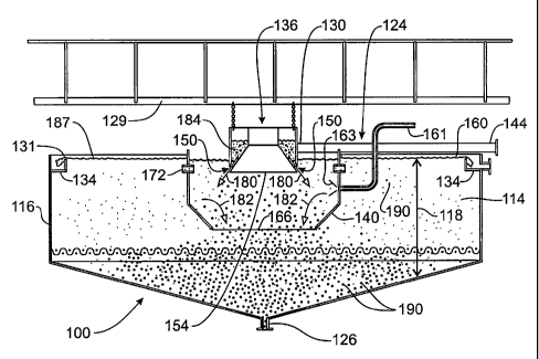
[0014] Figure 1 is cross-sectional view of an embodiment of a sedimentation
vessel that
includes a feed system according to the present embodiments;
[0015] Figure 2A is cross-sectional view of the embodiment of the feed system
of Figure 1;
[0016] Figure 2B is a perspective view of the embodiment of the feed system of
Figure 1;
[0017] Figure 3A is cross-sectional view of another embodiment of a feed
system that may be
used in the sedimentation vessel of Figure 1;
[0018] Figure 3B is a perspective view of the embodiment of the feed system of
Figure 3A;
[0019] Figure 4A is a top view of the embodiment of the feed system of Figure
2A showing
the flow pattern of the slurry out of the feedwell;
[0020] Figure 4B is a side view of the flow pattern of Figure 4A; and
[0021] Figure 5 is a perspective view of an embodiment showing the flow
pattern of the slurry
out of a sedimentation vessel.
DETAILED DESCRIPTION
[0022] The presently preferred embodiments of the present invention will be
best understood
by reference to the drawings, wherein like parts are designated by like
numerals throughout. It
will be readily understood that the components of the present invention, as
generally described
and illustrated in the figures herein, could be arranged and designed in a
wide variety of different
configurations. Thus, the following more detailed description of the
embodiments, as
represented in the Figures, is not intended to limit the scope of the
invention, as claimed, but is
merely representative of presently preferred embodiments of the invention.
[0023] Referring now to Figure 1, a cross sectional view of a sedimentation
vessel 100 is
shown. The sedimentation vessel 100 may be referred to as a thickener or a
clarifier. It should be
noted that the configuration of the sedimentation vessel 100 is provided for
illustrative purposes
only. There are a variety of other configurations that may be used for the
sedimentation vessel
100. For example, the sedimentation vessel 100 may be rectangular, circular,
or any other
desired shape.
-5-
CA 02782933 2012-06-05
WO 2011/071580 PCT/US2010/049443
[0024] As its name suggests, the sedimentation vessel 100 is designed to
separate most of the
solid particles 190 or materials from a liquid 187. Such a separation process
occurs because of
principles explained by Stokes law, wherein the solids 190 settle to the
bottom of the
sedimentation vessel 100 while the clarified liquid 187 is extracted from the
top of the vessel
100. The sedimentation vessel 100 includes a separation chamber 114, which in
the embodiment
of Figure 1, is shown as a cylindrical unit. As noted above, other
configurations are also
possible. The separation chamber 114 is defined by one or more outer walls
116. The volume
within the chamber 114 comprises the separation zone 118, which is a zone
where separation of
the solids and liquids occurs because of, for example, the force of gravity.
(The separation zone
may span the entire vertical height of the chamber 114). As the solids 190
settle to the bottom of
the chamber 114, scrapers or gravity may be used to accumulate thickened
slurry at the bottom of
the chamber 114 into an exit 126.
[0025] When added to the sedimentation vessel 100, the solids 190 and liquids
187 are
generally combined into a slurry 184 (which may also be referred to as a "feed
slurry"). The
majority of solids 190 will settle to the bottom of the separation zone 118,
and the liquid 187,
that may still contain solids 190, will rise to the top of the vessel 100. The
separation process
may be continuous when the rise rate or upflow velocity of the feed slurry 184
in the vessel 100
(i.e., the rate at which the slurry rises in the vessel 100) is lower than the
settling velocity of the
majority of solids 190 contained in the feed slurry 184. A continuous process
means that the
process may be continuously run, with a new quantity of slurry being
consistently injected into
the vessel 100.
[0026] The clarified liquid 187 found in the chamber 114 will generally be
collected at or near
the top of the chamber 114. Specifically, a weir 131 may be used such that the
liquid can
overflow from the weir 131 (which may be a "vee notch" weir) and be captured
into a launder
134.
[0027] The sedimentation vessel 100 includes a feed system 124. The feed
system 124 may
be designed to introduce the solid and liquid mixture (slurry) into the
separation zone 118. There
are a variety of different types of feed systems 124. Figure 1 shows a feed
system 124 that
comprises a feed pipe 130 that delivers the solid/liquid mixture (or slurry)
into a feed chamber
136. This feed chamber 136 distributes the feed evenly (as described herein)
into a feedwell 140.
-6-
CA 02782933 2012-06-05
WO 2011/071580 PCT/US2010/049443
One or more external tanks (or other collection/storage structures, which are
not shown in Figure
1) may also be used as part of the feed system 124.
[0028] The feed slurry may be introduced into the feed system 124 via an inlet
144. The inlet
144 may be any structure that is capable of receiving a quantity of the feed
slurry 184 and/or
introducing the feed slurry into the feed system 124. The inlet 144 may be
positioned on a feed
pipe 130, feed chamber 136, or other feed structure (such as an external
tank). In the
embodiment of Figure 1, the inlet 144 is located at the entry of the feed pipe
130. The feed
chamber 136 may be attached to a bridge 129 (or walkway) that is positioned
above the feedwell
140.
[0029] The slurry 184 enters the feed system 124 via the inlet 144 and then
flows (such as via
the pipe 130) into the feed chamber 136. One or more ports 150 are positioned
on the feed
chamber 136, such as for example, at the base 154 (bottom) of the feed chamber
136. The slurry
is allowed to exit the feed chamber 136 into the feedwell 140 by passing
through one or more
port(s) 150. Each port 150 may be in the form of openings or a continuous gap
in the wall of the
feed chamber 136. In some embodiments, the port 150 may be submerged below the
surface 160
of the liquid 187 in the sedimentation vessel 100. The port 150 may also be
positioned below the
top of the feedwell 140.
[0030] The feed system 124 also includes an outlet 166 which allows all of
feed slurry to exit
the feed system 124 into the sedimentation vessel 100. In the embodiment of
Figure 1, the outlet
166 may be an open bottom of a feedwell 140. Other types of outlets may also
be used. Further,
embodiments may be constructed in which optional ports 172 and/or gates (not
shown) on the
feedwell 140 allow lower density liquid 187 from the exterior of the feedwell
140 to flow into
the interior of the feedwell 140. The interior slurry may be generally at a
higher specific gravity
than the liquid exterior to the feedwell, and thus a density gradient may
operate to force the lower
density liquid through the ports 172.
[0031] As noted above, a variety of different feed systems 124 are possible
within the present
embodiments. For example, the feed system may comprise a feed distributer, a
feed pipe, and/or
a feed launder. Such structures may be used in addition to a feed chamber
136/feedwell 140
combination. All of these feed systems 124 may be used in sedimentation
vessels 100.
-7-
CA 02782933 2012-06-05
WO 2011/071580 PCT/US2010/049443
[0032] This embodiment of a feed structure 124 also dissipates feed stream
velocity and
momentum. Specifically, when the slurry enters the feed chamber 136, the
chamber dissipates
the kinetic energy associated with the flowing slurry. The feed slurry 184
then proceeds to the
feedwell 140 through the narrow port 150 in a non-segregated manner such that
the flow of the
slurry has an even flow pattern. When the slurry enters the feedwell 140 in
this manner, the user
can control the processes in the feedwell 140 such that the addition of
dilution water (or liquid)
through ports 172 and/or the addition of chemicals 163 (e.g., via pipe 161)
used for conditioning,
coagulation and flocculation may be done in a controlled and proportional
manner that optimizes
reaction kinetics, chemical efficiency and solids settling characteristics.
Thus, the conditions
associated with the separation may be optimized for each particular
application using the feed
system 124. Using the present embodiments, dilution of the feedwell 140,
flocculation of the
feedwell 140 (e.g., via chemicals 163) and/or even distribution of the slurry
exiting the feedwell
140 may all be obtained, even for a feedwell 140 having a large diameter.
[0033] The introduction of the feed into the separation zone 118 at a
relatively uniform
velocity and direction can be important both in terms of the efficiency of the
sedimentation
device and the solid's settling characteristics. Thus, in certain embodiments,
the flow pattern
inside the feedwell 140 is generally directed radially outward (as shown by
arrows 180) at a
downward angle from horizontal from the feed chamber 136 into the feedwell
140. The flow
then has to change direction back towards the center (as shown by the arrows
182) in order to
exit the feedwell 140. This change in direction and even flow distribution
limits "short
circuiting" of the sedimentation vessel. Short circuiting is when a
proportionally higher velocity
flow stream inside the separation chamber 114 is directed at the overflow weir
131. (In other
words, a disproportionate amount of the slurry 184 is directed towards one
area of the
sedimentation vessel 100, thereby resulting in inefficient operation of the
device). Short
circuiting will result in the undesired carry over of solids into the launder
134. If short circuiting
occurs, it must be overcome by using more chemicals and/or slowing the flow of
the slurry,
thereby reducing the efficiency of the sedimentation device 100.
[0034] Referring now to Figures 2A and 2B, the feed system 124 of Figure 1
will be described
in greater detail. Figure 2A is a cross-sectional view of the feed system 124
whereas Figure 2B is
a perspective view of the same structure. The feed structure 124 may be used
in the
-8-
CA 02782933 2012-06-05
WO 2011/071580 PCT/US2010/049443
sedimentation vessel, for example, as shown in Figure 1. All or a portion of
the feed chamber
136 may be positioned above the top 196 of the feedwell 140.
[0035] The slurry 184 is not shown in Figures 2A or 2B for purposes of
clarity. The slurry
184 will flow through the feed pipe 130 and will enter the feed chamber 136.
As can be seen
from Figures 2A and 2B, the slurry 184 may be introduced into the feed chamber
136 in a
tangential manner (e.g., parallel or substantially parallel to the top of the
feedwell 140).
[0036] Angular momentum of the slurry 184 entering the chamber 136 will carry
solids in a
circular manner (as shown by the arrow 200 in Figure 2B) in the feed chamber
136, thereby
minimizing the segregation of the fine solid materials ("fines") and the
heavier solid particles.
This circular flow 200 also assists in ensuring that the flow of the slurry
reaches the furthest end
204 of the feed chamber 136 from the feed pipe 130 in a homogeneous or a
substantially
homogeneous manner. The segregation of solids (into fines and heavy solid
particles) within the
feed chamber 136 or the feedwell 140 should be avoided to reduce uneven
deposition of the
heavier solids in isolated areas (sometimes referred to as "sand islands").
The formation of such
sand islands will create torque spikes or trip the drive mechanisms in
sedimentation vessels using
a raking device, or (where rakes are not used) lead to slumping (sinking) of
built up solids that
may operate to plug the sedimentation device.
[0037] The feed chamber 136 includes a port 150. As shown in Figures 2A and
2B, the port
150 is positioned at the base 154 of the feed chamber 136. The feed slurry 184
flows through the
port 150 into the feedwell 140. In the shown embodiment, the port 150 is a
continuous gap 150
that extends around the circumference 171 of the feed chamber 136. In other
embodiments, the
port 150 may be one or more openings (holes) through which the slurry 184 may
flow.
[0038] There is a potential that solids within the slurry may buildup and/or
block the port 150.
This blockage is undesirable as it will inhibit the flow of the slurry 184
into the feedwell 140. In
order to reduce the likelihood of such blockages, the walls 210 of the feed
chamber 136 are
vertical or at a steep angle relative to horizontal. The use of such steep
wall angles reduces the
likelihood that solids will build up and result in a blockage occurring.
[0039] A central wall 216 may be positioned within the feed chamber 136. As
shown in
Figures 2A and 2B, the central wall 216 is generally conical in shape, meaning
that it is tapered
such that a top portion 220 of the wall 216 has a smaller diameter than a
bottom portion 221
-9-
CA 02782933 2012-06-05
WO 2011/071580 PCT/US2010/049443
(conical portion) of the wall 216. The bottom 224 of the wall 216 is
positioned proximate the
port 150.
[0040] In some embodiments, the positioning of the feed chamber 136 may be
significant.
The feed chamber 136 is positioned upstream of the feedwell 140. As shown in
the Figures, the
port 150 is located below the surface of the liquid in the feedwell 140. The
feed chamber 136
thus creates a pressure differential (sometimes referred to as a "head")
between the incoming
feed pipe 130 and the feedwell 140. This means that the slurry upstream of the
port 150 (e.g.,
such as in the feed pipe 130) is at a greater pressure than the slurry
downstream of the port 150
(e.g., in the feedwell 140). This pressure differential is created because of
the small surface area
associated with the port 150 through which the slurry must flow. However, the
restriction to
flow is overcome by pressure buildup behind the port 150, as manifested in an
increased water
level in the feed chamber 136.
[0041] The area of the feed chamber 136 opening into the feedwell 140 (e.g.,
proximate the
port 150) may have smaller cross sectional area than other areas of the feed
chamber 136. The
reason for this is to create a flow resistance proximate the port 150. When
the slurry 184 enters
the feed chamber 136, the slurry 184 will generally follow the path having the
lowest amount of
resistance, and as the resistance to flow is higher in areas experiencing
higher flow rates, because
of associated turbulence and frictional losses, than areas of lower flow
rates, the lower flow areas
will attract more flow of the incoming slurry 184. In turn, this flow pattern
operates to balance
the flow through the feed chamber 136 (provided that the resistance to flow is
sufficient) such
that a balanced flow in all areas of the chamber 136 may be achieved.
[0042] The use of the feed chamber 136 upstream of the feedwell 140 also
dissipates some of
the feed stream energy by way of the induced headloss created by the port 150.
Specifically,
there is energy associated with the flow of the slurry 184 through the feed
pipe 130. All or a
portion of this kinetic energy is dissipated by turbulence and friction in the
feed chamber 136
(and the fact that the feedwell 140 is at a lower pressure than the feed
chamber 136). As such,
additional steps to dissipate the flow energy within the sedimentation vessel
100 may not need to
be taken.
[0043] After flowing through the port 150, the slurry 184 enters the feedwell
140. In some
embodiments, the flow out of the feed chamber 140 is directed radially outward
toward the wall
-10-
CA 02782933 2012-06-05
WO 2011/071580 PCT/US2010/049443
230 of the feedwell. As shown by the arrows 240, the flow of the slurry is
diagonally downward
and outward (radial) from the feed chamber 136. At the same time, a lower wall
250 of the
feedwell 140 is tapered (angled) toward the center 260 of the sedimentation
vessel. This means
that the lower wall 250 tapers inwardly. The outlet 166 is positioned at the
bottom of the lower
wall 250. Accordingly, after flowing outward toward the wall 230, the flow
path of the slurry
184 has to change direction back toward the center of the sedimentation device
in order to pass
by the inwardly tapered lower wall 250 (as shown by the arrows 241). The
outlet 166 of the
feedwell 140 is an open bottom so that the slurry can exit the feedwell 140
into the sedimentation
vessel. By making the slurry 184 flow in this manner, the possibility that
there will be an uneven
distribution of flow throughout the sedimentation vessel is reduced.
[0044] Figures 3A and 3B show another embodiment of a feed structure 324 that
may be used
in conjunction with the sedimentation vessel 100 of Figure 1. The feed
structure 324 is similar to
the feed structure 124 previously described. For purposes of brevity, this
description will not be
repeated.
[0045] The feed structure 324 includes a feed pipe 130 that distributes a
quantity of feed
slurry 184 (shown in Figure 1) into the feed chamber 136. The feed chamber 136
includes one or
more ports 150a through which the slurry 184 (not shown) may pass to enter the
feedwell 140.
Unlike the embodiment described above, the ports 150a do not comprise a
continuous gap in the
feed chamber 136. Rather, the ports 150a comprise one or more openings (such
narrow
openings) that are distributed proximate the bottom floor 354 of the feed
chamber 136 through
which the slurry 184 may flow to enter the feedwell 140.
[0046] Further, in the embodiment shown in Figures 3A and 3B, the feed chamber
136
includes a central wall 316. However, unlike the embodiment discussed above,
the central wall
316 is cylindrical in shape rather than conical. There is not a tapered
configuration in the
diameter of the central wall 316 (as is present in the wall 216). Rather, the
slurry 184 will enter
the feed chamber 136, contact the central wall 316, and flow out of the ports
150a into the
feedwell 140.
[0047] Referring now to all of the Figures, specific advantages of the present
embodiments
will now be discussed. A typical problem associated with the use of a feedwell
is the uneven
flow of the slurry out of the feedwell. (This problem is sometimes referred to
as "short-
-11-
CA 02782933 2012-06-05
WO 2011/071580 PCT/US2010/049443
circuiting" the feedwell, as indicated above). An optimal flow pattern out of
a circular feedwell
results in substantially equal amounts of the slurry flow out around the
entire circumference (e.g.,
360 degrees) of the feedwell. However, short-circuiting occurs when a
disproportionate amount
of the slurry flows out of one area of the feedwell. This leads to an
inefficient use of the volume
of the sedimentation vessel, and thus an inefficient separation process. Short-
circuiting may also
lead to a premature carry over of solids, meaning that some of the solids 190
will flow over the
weir 131 and not separate out from the liquid 187. In order to overcome this
inefficiency, the
flow rate of the slurry must be adjusted and/or additional chemicals (such as
coagulation or
flocculation chemicals) must be added. However, changing the flow rate and/or
using addition
chemicals add to the costs of the overall process.
[0048] The present embodiments address the issues associated with short-
circuiting. Figures
4A-4B show a flow pattern 400 of the slurry 184 using the embodiment of Figure
1. (A similar
flow pattern diagram is associated with the embodiment of Figure 3A). As shown
by these
Figures, the slurry 184 flows out of the feedwell 140 in a substantially even
manner, such that
substantially even amounts of slurry 184 flow out of the entire circumference
(e.g., 360 degrees)
of the feedwell 140. This flow pattern 400 can be described as having a
concentric profile 410,
which means that the flow pattern approximates a series of concentric rings
formed as the slurry
184 flows outward from the feedwell 140. This flow pattern allows for a more
efficient use of
the volume of the sedimentation vessel 100. (The flow pattern for a
sedimentation vessel 100
that is short-circuited would have a disproportionate amount of slurry 184
flowing out of a side
of the feedwell 140).
[0049] Figure 5 shows a flow pattern 500 of the slurry 184 using the
embodiment of a typical,
industry standard, feedwell 540 arrangement. As shown by this figure the flow
distribution
pattern 500 of slurry is directed to the one side of the sedimentation vessel
100. By not using the
entirety of the settlement area provided by the sedimentation vessel the
effective rise rate (Area
of the sedimentation vessel divided by the feed flow rate) is increased. The
higher net rise rate
allows fine particles 190 to be carried over the weir 131. To counteract the
premature carryover
of solids 190 either more chemical reagentl63 must be added, which has a cost
implication or
the feed 184 flow rate must be reduced which may have the effect of lost
production.
-12-
CA 02782933 2012-06-05
WO 2011/071580 PCT/US2010/049443
[0050] The present embodiments also relate to a method for increasing
efficiency within a
sedimentation device 100. This method comprises obtaining a feedwell 140, the
feedwell 140
comprising an outlet 166 through which slurry 184 may flow into a
sedimentation vessel 100.
The method also comprises obtaining a feed chamber 136, the feed chamber 136
comprising a
central wall 216 or 316, and at least one port 150 and/or 150a positioned at
the base 154 of the
feed chamber 136. The feed chamber 136 is installed proximate the feedwell 140
such that when
installed, the slurry 184 will pass through the feed chamber to the port 150
or 150a, into the
feedwell 140 via the port 150 and/or 150a, through the feedwell 140 to the
outlet 166, and
through the outlet 166 into the sedimentation vessel 100. The process method
is that the feed
184 is firstly evenly distributed into the feedwell 140, then dilution water
187 is added through
ports 172 (if required) and mixed with the feed. The chemical reagent can be
added at the ports
172 or anywhere in the feedwell 140. The liquid 187, feed slurry and chemical
reagent 163 are
mixed in the body of the feedwell 140. The flocculated solids are then
introduced into the
separation zone 118 in an even flow rate through opening 166. In some
embodiments, this
method may be performed by retro-fitting an existing sedimentation device
having a feedwell
with a feed chamber 136.
[0051] The present invention may be embodied in other specific forms without
departing from
its structures, methods, or other essential characteristics as broadly
described herein and claimed
hereinafter. The described embodiments are to be considered in all respects
only as illustrative,
and not restrictive. The scope of the invention is, therefore, indicated by
the appended claims,
rather than by the foregoing description. All changes that come within the
meaning and range of
equivalency of the claims are to be embraced within their scope.
[0052] What is claimed is:
-13-