Note: Descriptions are shown in the official language in which they were submitted.
CA 02782993 2016-11-01
Electric Machine
The present invention relates to an electric machine comprising a rotor
equipped
with permanent magnets and a stator equipped with electromagnetic poles.
Such electric machines, having the permanent magnets uniformly distributed on
io the rotor and the electromagnetic poles uniformly distributed on the
stator, have
already been used as electric motors and generators for decades. In this
regard,
great expenditures have been taken for improving the performance and the effi-
ciency of such machines. Nevertheless, there are considerable losses arising
dur-
ing operation of such machines. Such losses do not only affect the efficiency
of
the electric machine, but entail still other problems. In operation, in
particular the
rotor of conventional electric machines is subject to great heat,
necessitating
comprehensive cooling requirements for the machine in its entirety.
Accordingly, an example feature underlying the present invention consists in
making avail-
able an electric machine having reduced power losses in the rotor in
comparison
with the prior art described.
The electric machine comprises a rotor equipped with permanent magnets and a
stator equipped with electromagnetic poles. The electric machine is
characterized
in that several adjacent electromagnetic poles respectively constitute an
electro-
magnetic pole group in which the adjacent electromagnetic poles are spaced
apart at a first electromagnetic pole spacing, that adjacent electromagnetic
poles
belonging to different electromagnetic pole groups are spaced apart at an
electro-
magnetic pole spacing that is greater than said first electromagnetic pole
spacing,
that each electromagnetic pole group has an even number of electromagnetic
poles, and that adjacent electromagnetic poles of an electromagnetic pole
group
are linked to each other so as to generate magnetic fields of opposite
direction in
operation.
CA 02782993 2016-11-01
2
Due to the groupwise arrangement and linking, in circuit terms, of an even num-
ber of electromagnetic poles, long-range magnetic flux in the electric
machine, in
particular through the rotor, is reduced drastically or avoided completely. A
short,
closed path is so to speak forced upon the magnetic flux in an electromagnetic
pole group. A closed magnetic flux path normally leads from a first
electromagnet-
ic pole via an air gap between stator and rotor through permanent magnets of
the
rotor to the rotor yoke, from there through permanent magnets of the rotor,
through the air gap to a second electromagnetic pole of the same
electromagnetic
pole group and through the stator core back to the original electromagnetic
pole.
With the even distribution of the electromagnetic poles without groupwise
linking
in circuit terms, according to the prior art, there are often formed closed
flux loops
in which the flux lines extend over large distances in the rotor between two
re-
mote permanent magnets; accordingly, there are also present long-range effects
in the stator, covering a multiplicity of electromagnetic poles. In contrast
thereto,
the present invention brings forth excellent prerequisites to the effect that
the
magnetic fields close within an electromagnetic pole group. The individual
electro-
magnetic pole groups are spaced apart from the respective adjacent electromag-
netic pole groups so that the coupling within one group is greater than the
cou-
piing between electromagnetic poles of different electromagnetic pole groups.
The arrangement can thus prevent long-range magnetic flux through the
rotor, which results in a reduction of the losses arising in connection with
such
magnetic fluxes. The reduction of the losses is accompanied by a reduction of
the
heat caused by losses. In addition to the reduction of the heat generated, the
present invention provides the advantage that the space created between respec-
tive electromagnetic pole groups, which is not occupied by the coils of an
electro-
magnetic pole, can be utilized for cooling. To this end, this space may be
left free
as an air gap in order to provide for air flow through this gap for cooling
purposes.
oo The intermediate space may also be used for accommodating cooling
devices. As
will be discussed in detail later on, the creation of this intermediate space
be-
tween the electromagnetic pole groups affords the additional advantage of con-
siderably facilitating both the manufacture of the individual components of
the sta-
tor and the mounting of these components to a stator body.
In preferred embodiments, two adjacent electromagnetic poles respectively con-
stitute an electromagnetic pole group. Alternatively, four adjacent
electromagnetic
=
WO 2011/069849 , 02782993 2012 06 05
PCTTEP2010/068368
3
poles respectively constitute an electromagnetic pole group. Such a
comparative-
ly small number of electromagnetic poles per electromagnetic pole group
entails
several advantages. A small number of electromagnetic poles per electromagnet-
ic pole group results in a large number of electromagnetic pole groups. These
in
6 turn may be driven such that many partial phases are applied to the
various elec-
tromagnetic pole groups, leading to very smooth running of a thus controlled
elec-
tric motor and/or little generation of noise in operation of the electric
machine.
Moreover, the electromagnetic poles of comparatively small electromagnetic
pole
groups can be driven together easily. However, an electromagnetic pole group
ro may also comprise 6 or 8 or still more electromagnetic poles.
In a preferred embodiment, the electric machine is characterized in that the
re-
spective electromagnetic pole spacing between adjacent electromagnetic poles
belonging to different electromagnetic pole groups, as measured in the
magnetic
15 phase angle of the permanent magnets, is at maximum 400, preferably at
maxi-
mum 30 , greater than it would be with an equidistant distribution of the
electro-
magnetic poles across the stator. The electromagnetic pole spacing in this
regard
is defined as the angle between the two centers of the given electromagnetic
poles. In like manner, the permanent magnet spacing, also referred to as rotor
20 pole spacing, is the angle between the two centers of the given
permanent mag-
nets, also referred to as rotor poles. The permanent magnets are uniformly dis-
tributed on the circumference and are, in radial direction, alternatingly
polarized in
opposite directions. There is formed a magnetic phase angle of 180 between
the
centers of juxtaposed permanent magnets. Accordingly, an increase of the elec-
25 tromagnetic pole spacing by 30 , as measured in the magnetic phase angle
of the
permanent magnets, corresponds to an increase by (30/180)* permanent magnet
spacing. By way of this structure, an electric machine with the following
properties
can be made available. The amount of the voltage induced in the
electromagnetic
poles of an electromagnetic pole group does not deviate by more than 3% from
30 the value of the induced voltage in case of an equidistant pitch of the
stator, i.e. in
case of uniform distribution of all stator electromagnetic poles around the
stator
circumference. Between the coils of different electromagnetic pole groups,
there
is a coupling ratio of at the most 0.2. Due to this, the electric machine is
designed
such that the performance is not significantly different from the performance
of an
35 electric machine with uniformly distributed stator electromagnetic
poles, and such
that there is little coupling between adjacent electromagnetic pole groups, so
that
k
:A 02782993 2012 06 05
WO 2011/069849
PCT/EP2010/068368
4
the above-discussed short magnet flux loops result in conjunction with the
linking
within an electromagnetic pole group.
The afore-mentioned numerical value for the deviation of the electromagnetic
pole
spacing from an equidistant electromagnetic pole spacing about the stator
circum-
ference also has turned out advantageous in so far as, in comparison with the
winding or iron volume lost, a sufficient width of the groove between the
stator
teeth of an electromagnetic pole group for accommodating the electromagnetic
pole coils and a sufficient geometric additional width of the groove between
adja-
io cent electromagnetic pole groups are formed. The electromagnetic pole
spacing
between adjacent electromagnetic poles belonging to an electromagnetic pole
group is adjusted in accordance with the selected spacing between adjacent
elec-
tromagnetic pole groups. The electric machine is operated such that adjacent
electromagnetic poles within a group have opposite magnetic fields at an
arbitrary
time of operation, so that the geometric spacing between two adjacent electro-
magnetic poles of an electromagnetic pole group corresponds to an electric/mag-
netic phase angle of approx. 180 .
It is also possible to design the electric machine such that the respective
electro-
n magnetic pole spacing between adjacent electromagnetic poles
belonging to the
same electromagnetic pole groups are set to lower values than the value that
would be present in case of an equidistant distribution of the electromagnetic
poles across the stator. This arrangement also permits the achievement of the
afore-mentioned advantages as regards the reduced electromagnetic pole spac-
ing within an electromagnetic pole group and the increased spacings between ad-
jacent electromagnetic pole groups. It can be seen that the relationship
between
the increased electromagnetic pole spacing between two groups and the reduced
electromagnetic pole spacing within the individual electromagnetic pole groups
is
dependent upon the number of electromagnetic poles per electromagnetic pole
so group. In preferred embodiments, the electromagnetic pole spacing
between ad-
jacent electromagnetic poles belonging to different electromagnetic pole
groups is
substantially greater than in case of an equidistant distribution of the
electromag-
netic poles across the stator, and in particular is by far greater than the
differ-
ences in the electromagnetic pole spacings that are due to normal
manufacturing
tolerances.
:A 02782993 2012 06 05
WO 2011/069849
PCT/EP2010/068368
It is particularly preferred for the electromagnetic pole spacing between
adjacent
electromagnetic poles belonging to different electromagnetic pole groups to be
2400, as measured in the magnetic phase angle of the permanent magnets. In
other words, the electromagnetic pole spacing is 4/3 times the rotor pole
spacing.
5 This achieves especially effective decoupling between the two
electromagnetic
pole groups. In addition thereto, electromagnetic pole groups spaced apart in
this
manner can be directly associated with the phases of a 3-phase system.
In a preferred embodiment, adjacent electromagnetic poles belonging to
different
lo electromagnetic pole groups each have a second electromagnetic pole
spacing.
Such an arrangement, leading to a regular construction of the electric machine
as
regards the spacings of the respective electromagnetic pole groups, which may
also be referred to as partially symmetric, presents a number of advantages.
On
the one hand, the stator may be composed entirely of identical stator compo-
16 nents, with each component having exactly one or more electromagnetic
pole
group(s) and exactly one or more additional width(s) for the groove(s) between
electromagnetic pole groups. On the other hand, adjacent electromagnetic pole
groups have the same spacing across the entire stator circumference, so that a
uniform construction is achieved as regards the utilization of the additional
groove
zo width between the electromagnetic pole groups, e.g. for cooling of the
electric ma-
chine or for mounting the electric machine. Such a uniform construction may
also
be advantageous for the performance of the machine. In accordance with the
driving scheme of the machine, the phasing of the various magnetic fields in
rela-
tion to each other during operation and the requirements as to the residual
ripple
26 of the electric machine, however, it may also be advantageous not to
arrange the
electromagnetic pole groups with a constant spacing from each other. The term
"residual ripple" of the electric machine is to be understood here as the non-
con-
stant course or behavior of the torque which the electric machine experiences
in
operation upon rotation of the rotor due to the geometric construction and the
30 driving scheme.
In a further preferred embodiment, the permanent magnets have a rotor pole
spacing, with the rotor pole spacing being different from the electromagnetic
pole
spacing, and being preferably smaller than the same. This embodiment is espe-
35 daily advantageous as regards the performance and the low residual
ripple of the
electric machine.
:A 02782993 2012 06 05
WO 2011/069849
PCT/EP2010/068368
6
Adjacent electromagnetic poles of an electromagnetic pole group produce mag-
netic fields in opposite direction in operation. The magnetic field direction
here re-
lates to the radially extending part of the magnetic field through the air gap
be-
tween stator and rotor. In other words: when a magnetic field is created from
an
electromagnetic pole in the stator to the rotor, the magnetic field extends
from the
rotor to the adjacent electromagnetic pole of the same electromagnetic pole
group. Thus, in operation there is formed a closed magnetic flux loop through
two
adjacent electromagnetic poles of an electromagnetic pole group. Due to the
fact
that each electromagnetic pole group has an even number of electromagnetic
poles, there are thus formed only short-range magnetic loop within an electro-
magnetic pole group. This minimizes the losses arising in the rotor, which in
turn
leads to the advantages discussed hereinbefore.
The linking of adjacent electromagnetic poles of an electromagnetic pole group
16 according to the invention, such that these generate magnetic fields of
opposite
direction in operation, can be achieved in a large variety of ways. On the one
hand, a connection of adjacent electromagnetic poles can be established on a
wiring level. Adjacent electromagnetic poles may be connected in series so
that
magnetic fields of opposite direction are formed in the adjacent
electromagnetic
zo poles. To this end, the wiring is devised such that the current, as seen
in radial di-
rection, flows through two adjacent coils of two adjacent electromagnetic
poles in
opposite directions, i.e. in one coil in clockwise direction and in the other
coil in
anticlockwise direction. In an electromagnetic pole group consisting of two
elec-
tromagnetic poles, the two electromagnetic poles may be connected in series;
in
25 an electromagnetic pole group consisting of four electromagnetic poles,
all four
electromagnetic poles may be connected in series. On the other hand, the elec-
tromagnetic poles may be controlled electronically. In this case, the adjacent
elec-
tromagnetic poles may be connected to different terminals fed by an (or more,
re-
spectively) control electronics. The electronics system provides for a
correspond-
30 ing driving scheme of the electromagnetic poles for generating
corresponding
magnetic fields of opposite direction. There are also solutions conceivable in
which sub-groups of the electromagnetic poles are connected in series, whereas
different sub-groups are controlled through different electronics terminals.
36 In accordance with a preferred embodiment of the invention, each of the
electro-
magnetic poles comprises a stator tooth and a coil surrounding the stator
tooth,
with winding grooves respectively being provided between two stator teeth, for
ac-
_
, .
WO 2011/069849 , 02782993 2012 06 05
PCT/EP2010/068368
7
commodating the coils. Thus, in assembling the electric machine, the coils
conve-
niently may be placed onto the stator teeth. For this purpose, rigid, not
loosely
wound coils are especially - but not exclusively - suitable. The shape of the
grooves within an electromagnetic pole group preferably is rectangular. Rectan-
6 gular in this regard is to be understood that the grooves in cross-
section form re-
cesses having substantially right angles. Consequently, the stator teeth in a
pre-
ferred embodiment are formed with tapering lateral edges, i.e. they are trape-
zoidal in cross-section. It can be seen that the sliding insertion of the
coils onto
the stator teeth according to the present embodiment is particularly
convenient in
io the mounting operation. It is of course also possible to wind the coil
windings di-
rectly onto the stator teeth. The grooves between different electromagnetic
pole
groups may be of rectangular cross-section as well, but preferably are not of
rect-
angular cross-section. These inter-group grooves in particular may make use of
any shape providing space for the coils extending around the adjoining stator
15 teeth and making optimum use of the remaining space for desired
additional func-
tions.
In a preferred embodiment, a temperature sensor and/or cooling means is/are
provided between adjacent electromagnetic poles belonging to different electro-
n, magnetic pole groups. In this manner, the free space present between
different
electromagnetic pole groups is utilized for temperature monitoring of the
electric
machine and/or for cooling the same. Together with the reduction of the rotor
losses and thus the reduced heating of the rotor as a result of the even
number of
electromagnetic poles per electromagnetic pole group, the active cooling of
the
25 electric machine affords additional advantages. The electric machine may
be op-
erated in the maximum performance mode, subjecting the machine to maximum
heating, over a longer period of time. The requirements as to cooling times
and,
respectively, operational times involving less heating are reduced. In
addition
thereto, the electric machine in its entirety may be of more compact design or
may
30 be arranged in a smaller housing since the requirements for cooling
means out-
side the stator/rotor assembly are lower. The arrangement of a temperature sen-
sor in the free space between two electromagnetic pole groups entails the addi-
tional advantage that temperature detection takes place in immediate proximity
to
the rotor, requiring no complicated mounting of the sensor and no complicated,
35 e.g. wireless, transmission of the temperature signal to the control of
the electric
machine.
. ,
WO 2011/069849 , 02782993 2012 06 05
PCT/EP2010/068368
8
In a further embodiment, there are provided, between adjacent electromagnetic
poles belonging to different electromagnetic pole groups, mounting means for
mounting electromagnetic poles to a stator body. In this manner, the free
space
present between adjacent electromagnetic pole groups is utilized for
simplifying
and/or improving the assembly operation of the electric machine. The mounting
means may consist e.g. of a suitable design of an intermediate piece, so that
one
electromagnetic pole group is clamped between two such intermediate pieces
and is thus held in place. These intermediate pieces may be connected to the
sta-
tor body by means of screws, bolts etc. so that the electromagnetic poles are
lo fixed in position with respect to the stator body. Such fixing can be
effected expe-
diently, inexpensively and rapidly during the assembly operation. In addition,
it
can be released just as expediently, inexpensively and rapidly for maintenance
and repair work. An exemplary embodiment for such intermediate pieces are
grooved strips extending axially along the electric machine between two
electro-
magnetic pole groups each.
In a still further preferred embodiment, the stator has a stator core that is
inter-
rupted between adjacent electromagnetic poles belonging to different
electromag-
netic pole groups. By way of this arrangement, magnetic loops in the stator
core
extending over several electromagnetic pole groups are avoided. The generation
of short-range closed magnetic fields in two adjacent electromagnetic poles is
en-
hanced even further. The decoupling of the various electromagnetic pole groups
is enhanced even more with this constructional measure, whereby the above-dis-
cussed advantages concerning short magnetic flux loops present themselves
26 even more strongly. The interruption may be provided in the form of any
suitable,
non-magnetic material. This provides for a magnetic isolation between the
electro-
magnetic pole groups.
The interruption of the stator core may be designed as a mounting means for
so mounting electromagnetic poles to a stator body. The interruption thus
serves
both for the purpose of an improved construction with respect to the
assembling
and disassembling properties of the electric machine and for decoupling the
indi-
vidual electromagnetic pole groups. As an alternative, the interruption can be
de-
signed as a receiving means for a cooling means and/or a temperature sensor.
35 The interruption even may be designed so as to simultaneously serve as a
mounting means and as a receiving means for a cooling means and/or a temper-
ature sensor.
CA 02782993 2016-11-01
9
In a particularly preferred embodiment, a stator segment prefabricated as a
corn-
plete unit comprises the electromagnetic poles of an electromagnetic pole
group.
Such a complete unit can be prefabricated easily. Moreover, rapid and inexpen-
sive assembly of the stator from such prefabricated stator segments is
ensured,
with these segments in the assembly operation being merely fixed to a stator
body and connected to the control unit of the electric machine.
In accordance with a preferred embodiment, the electric machine comprises fur-
y) thermore first control electronics and second control electronics,
wherein one
electromagnetic pole group of a respective set of two adjacent electromagnetic
pole groups is connected to the first control electronics, with the
respectively other
electromagnetic pole group being connected to the second control electronics.
It
is possible in this manner to operate the electric machine with only two
control
electronics, thus contributing to low-complexity and inexpensive production of
the
electric machine.
As an alternative, a respective set of two adjacent electromagnetic pole
groups
can be connected to the same control electronics. In particular, the driving
scheme can be designed such that two adjacent electromagnetic pole groups are
connected to first control electronics, the next two electromagnetic pole
groups
are connected to second control electronics, the following next two electromag-
netic pole groups are connected to the first control electronics again, etc.
30
The invention will be explained in more detail hereinafter by way of
embodiments
illustrated in the drawings in which
WO 2011/069849 :A 02782993 2012 06 05
PCT/EP2010/068368
Fig. 1 shows a fragmentary cross-sectional view of a first embodiment of an
electric machine according to the invention; and
5 Fig. 2 shows a
fragmentary cross-sectional view of a second embodiment of
an electric machine according to the invention.
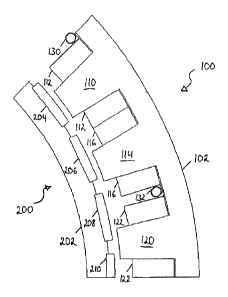
Fig. 1 shows a fragmentary cross-sectional view of an electric machine
according
to an embodiment of the present invention. The part illustrated shows a sector
of
to each of the stator
100 and the rotor 200. The part illustrated covers approx. 1/8 of
the overall circumference of the electric machine.
Stator 100 has a stator core 102. The stator core 102 comprises an annular por-
tion having three stator teeth 110, 114 and 120 extending inwardly therefrom.
The
stator teeth 110, 114 and 120 are of trapezoidal cross-section and are spaced
apart from each other. The stator teeth are surrounded by respective magnetic
coils. Stator tooth 110 constitutes a first electromagnetic pole together with
mag-
netic coil 112, stator tooth 114 constitutes a second electromagnetic pole
together
with magnetic coil 116, and stator tooth 120 constitutes a third
electromagnetic
zo pole together with
magnetic coil 122. In the exemplary embodiment of Fig. 1, the
stator teeth are formed of iron sheets and are the iron cores of the
respective
magnetic coils surrounding the same. The stator core 102 and the stator teeth
110, 114 and 120 are of integral design. However, they may also be composed of
several component parts.
Between the stator teeth, there are provided rectangular recesses. As seen
from
radially inside towards the outside, these recesses constitute rectangular
grooves
between the stator teeth, The magnetic coils 112, 116 and 122 also are of
rectan-
gular shape in cross-section, with the magnetic coils being of identical cross-
sec-
tion. The first and second electromagnetic poles together constitute a first
electro-
magnetic pole group. The third electromagnetic pole, together with a fourth
elec-
tromagnetic pole (not shown), constitutes a second electromagnetic pole group
adjacent said first electromagnetic pole group. The groove between stator
tooth
110 and stator tooth 114, i.e. the groove located within an electromagnetic
pole
group, is narrower than the groove between stator tooth 114 and stator tooth
120,
i.e. the groove located between two electromagnetic pole groups. The groove be-
tween stator tooth 110 and stator tooth 114 is exactly of such a width that
the
:A 02782993 2012 06 05
WO 2011/069849
PCT/EP2010/068368
11
sections of the magnetic coils 112 and 116 coming to lie in the groove in
essence
fill the groove width completely.
Due to the fact that the cross-sectional areas of the magnetic coils are
alike, it foi-
lows that an air gap is left free between magnetic coil 116 and magnetic coil
122
in the groove between stator tooth 114 and stator tooth 120. In the exemplary
embodiment of Fig. 1, a cooling duct 132 is arranged in this air gap. On the
oppo-
site side of the first electromagnetic pole group, beside magnetic coil 112,
there is
arranged an additional cooling duct 130. The cooling ducts 130 and 132 are
each
io disposed on the groove bottom, i.e. in immediate proximity to the stator
core 102.
It is also conceivable to shift these cooling ducts in radial direction to a
different
place in the air gap between the magnetic coils. The cooling ducts are of
round
cross-sectional area, and the diameter of the cooling ducts substantially
corre-
sponds to the air gap between the magnetic coils. It is also possible to use
other
cross-sectional areas and dimensions.
The illustrated section of rotor 200 shows an annular rotor core 202 having a
plu-
rality of permanent magnets attached thereto. The illustrated section shows
three
permanent magnets 204, 206 and 208 in full, whereas a fourth permanent mag-
net 210 can be seen in part only. The spacing between adjacent permanent mag-
nets is the same. The individual permanent magnets are also referred to as
rotor
poles in the present description, and the distance between the same as rotor
pole
spacing. The permanent magnets are magnetized such that, for each one, one of
the north and south poles is located on the side facing the stator and that,
accord-
the other one of their north and south poles is located on the side mounted
on the rotor core. The permanent magnets are arranged such that their
polarities
alternate.
In the embodiment of Fig. 1, the rotor pole spacing is smaller than the
spacing be-
tween adjacent electromagnetic poles, both within an electromagnetic pole
group
and also at the electromagnetic pole group boundaries. Due to this
configuration,
at least some of the relative positions of the individual permanent magnets,
in re-
lation to the respective opposite electromagnetic poles, are different at an
arbi-
trary time of operation. At the moment of time illustrated in Fig. 1,
permanent
magnet 204 comes to lie exactly opposite stator tooth 110 and the section of
magnetic coil 112 on one side of stator tooth 110. The permanent magnets 206,
WO2011/069849 , 02782993 2012 06 05
PCT/EP2010/068368
12
208 and 210, at the moment of time illustrated, have different relative
positions
each in relation to the respective opposite electromagnetic pole.
The respective torques resulting between opposite poles add up during
operation
such that the torque produced upon rotation of the rotor is as high as
possible
and as constant as possible. As is apparent to the person skilled in the art
in this
regard, the driving scheme of the magnetic coils with multi-phase control
signals
is of decisive relevance here. As the skilled person in the field of electric
ma-
chines is capable of indicating a suitable control, a detailed discussion of
this as-
pect is dispensed with here.
Rotor core 202, in the embodiment of Fig. 1, is shown to be annular. This
annular
rotor core 202, for operation of the electric machine, may be arranged on an
axle
to which I from which the movement of the rotor core 202 is transferred. The
axle
and the rotor core 202 may both be made of ferromagnetic materials. Axle and
ro-
tor core 202 may also be of integral design.
Operation of the electric machine, of which a part is shown in Fig. 1 in a
cross-
sectional view, will be explained hereinafter. It is presumed first that the
electric
zo machine of Fig. 1 is operated as an electric motor. Secondly, it is
presumed that
the rotor rotates in clockwise direction in the view illustrated. Thirdly, it
is pre-
sumed that, at the moment of time illustrated, the magnetic fields
electrically gen-
erated in the stator teeth 110 and 114 of the electromagnetic poles in radial
direc-
tion are of opposite polarity to the respective permanent magnets 204 and 206
lo-
cated largely opposite the same. The interaction of the magnetic fields of the
per-
manent magnets and the electrically generated magnetic fields thus results in
a
closed magnetic flux loop through stator tooth 110, through the air gap to the
"up-
per surface" of permanent magnet 204, from the "lower surface" of permanent
magnet 204 to the "lower surface" of permanent magnet 205 - which are of oppo-
site polarity -, through the air gap to stator tooth 114 and through the
annular por-
tion of stator body 102 to stator tooth 110. It can be seen in this regard
that, due
to the relative position of the permanent magnets to the electromagnetic
poles,
there is arising a force acting on the rotor in clockwise direction, It can be
seen in
addition that, with further rotation of the rotor and polarity reversal of the
electro-
n magnetic poles at a later moment of time - permanent magnet 204 at said
later
time is located in the position of permanent magnet 206 at the moment
illustrated,
a further permanent magnet (not shown) at said later moment of time is located
in
WO 2011/069849 , 02782993 2012 06 05
PCT/EP2010/068368
13
the position of permanent magnet 204 at the moment illustrated -, there is
again
formed a magnetic flux loop that is directed oppositely to the one described
above, but again exerts a force on the rotor in clockwise direction. In this
manner,
there is achieved a continuous operation of the electric motor, establishing
short-
s range magnetic flux paths.
Magnetic coil 116 is connected in series with magnetic coil 112 such that
magnet-
ic fields of opposite direction are created in the magnetic cores of the same,
i.e. in
stator teeth 110 and 114. In particular, time-variable magnetic fields are
electrical-
ly generated in the stator teeth 110 and 114, having phases that are displaced
from each other by 180 or, in other words, have the same amount, but are of
op-
posite polarity.
The afore-mentioned short-range magnetic flux paths can be achieved across the
entire electric machine by way of a corresponding driving scheme of the
magnetic
coils of the electromagnetic poles of the stator. This is due to the
decoupling of
the different electromagnetic pole groups as well as the provision of an even
num-
ber of electromagnetic poles within an electromagnetic pole group, through
which
long-range magnetic flux paths are avoided. As discussed hereinbefore, short-
range magnetic flux paths considerably reduce the losses arising in the
electric
machine, so that the development of heat in the electric machine is reduced as
well.
The heat development is efficiently counteracted in addition by the provision
of
the cooling ducts 130 and 132. The cooling ducts have a fluid, preferably a
cool-
ing liquid, flowing through the same, taking up the heat created in the
electric ma-
chine through the duct wall and transporting the same away, It is also
possible
that a plurality of cooling ducts extend in parallel between the magnetic
coils. The
illustrated cooling ducts 130 and 132 effect both transport of the waste heat
gen-
erated in the magnetic coils by the current and trasnport of the waste heat
pro-
duced by the varying magnetic fields in rotor core 202 and stator core 102. It
is
particularly efficient to insert the cooling ducts between the magnetic coils,
as a
particular hot spot of the electric machines described may be present at this
loca-
tion.
Fig. 2 shows a fragmentary cross-sectional view of an electric machine
according
to a second embodiment of the present invention. Components corresponding to
WO 2011/069849 , 02782993 2012 06 05
PCT/EP2010/068368
14
components of the embodiment of Fig. 1 are designated with the same reference
numerals. For reasons of better visibility, there is no rotor part shown in
Fig. 2. It
is presumed that the rotor has the design described in connection with Fig. 1.
Fig.
2 shows a somewhat larger sector of the stator, namely approx. 1/6 of the
total
6 stator. Due to the fact that the electromagnetic poles of the embodiment
accord-
ing to Fig. 2 are of identical design as the electromagnetic poles of the
embodi-
ment according to Fig. 1, Fig. 2 reveals a larger number of electromagnetic
poles,
to be precise four electromagnetic poles. As regards the second
electromagnetic
pole group, there is not only shown one electromagnetic pole, consisting of
stator
tooth 120 and magnetic coil 122 (as in case of Fig. 1), but also the second
elec-
tromagnetic pole, consisting stator tooth 124 and magnetic coil 126. Thus, in
total
two electromagnetic pole groups having two electromagnetic poles each are
shown, As in case of Fig. 1, a wider groove is provided between the adjacent
sta-
tor teeth 114 and 120 belonging to different electromagnetic pole groups than
be-
ts tvveen the adjacent stator teeth 110 and 114 as well as 120 and 124,
respectively,
belonging to the same electromagnetic pole groups. The advantages described
with reference to Fig. 1 thus can be read directly on the embodiment of Fig.
2.
The operation of the embodiment of Fig. 2 is comparable to the operation of
the
embodiment of Fig. 1.
The stator core 102 of the embodiment according to Fig. 2 is interrupted at
the
electromagnetic pole group boundary by an intermediate piece 136. In addition
thereto, the stator core 102 and the intermediate piece or interruption 136
are
confined radially outside by a stator body 140. In other words, stator core
102 and
intermediate piece 136 are mounted on an annular stator body 140. In the exem-
plary embodiment of Fig. 2, such mounting is effected by means of a screw 134.
By way of screw 134, intermediate piece 136 is fixed to stator body 140. At
the re-
spective other ends of the electromagnetic pole groups illustrated, there are
pro-
vided similar screws and similar intermediate pieces (not shown). Due to the
fixa-
tion of the intermediate pieces, the electromagnetic pole groups are clamped
be-
tween the intermediate pieces, as is apparent from simple geometric considera-
tions concerning circle segments. Accordingly, the components of the stator
may
be fixed by simply threadedly attaching intermediate pieces between the
electro-
magnetic pole groups. This ensures simple, rapid and inexpensive mounting and
unmounting possibilities of the stator. As an alternative/in addition to the
fixation
described, the individual electromagnetic pole groups may also be attached to
the
WO 2011/069849 , 02782993 2012 06 05
PCT/EP2010/068368
stator body 40 in a different suitable manner. The intermediate pieces may be
provided in the form of axially extending grooved strips or rods or bars.
Fig. 2 shows stator body 140 and intermediate piece 136 in hatched manner.
This
5 is to illustrate that these components are of non-magnetic design. This
means
that they consist, in the exemplary embodiment of Fig. 2, of a material that
does
not support the propagation of magnetic flux, i.e. of a non-ferromagnetic
material.
The two electromagnetic pole groups illustrated thus are magnetically
separated
from each other, In this manner, long-range magnetic flux paths, i.e. magnetic
flux
io paths extending across several electromagnetic pole groups, are further
reduced
in operation of the electric machine. The formation of short magnetic loops
across
the stator teeth of one electromagnetic pole group and a short flux path in
the ro-
tor is enhanced, resulting in the advantages discussed hereinbefore.
15 However, it is also possible that the intermediate pieces do not
interrupt the iron
core of the stator and provide for mechanical separation only, bringing about
the
afore-mentioned advantages for the assembly operation.
For fixing the intermediate pieces that may be in the form of grooved strips
ex-
tending in axial direction, bolts may be used as an alternative to screws.
Bolts or
screws may be arranged for example in a periodical, axially spaced manner.
Also,
elongate, axially extending connecting elements may be utilized. Cooling
devices
and/or temperature sensors may be accommodated in the intermediate pieces.
It is expressly emphasized that the roles of stator and rotor my be exchanged
in
all embodiments, The stator thus may have permanent magnets, and the rotor
may have electromagnetic poles. Instead of permanent magnets, there may also
be provided a second set of electromagnetic poles. As seen in radial
direction,
the stator may be arranged both outside and inside, with the immediate effect
that
the rotor may be arranged both outside and inside as well. A rotor/stator
combina-
tion according to the invention may be operated both as electric motor and as
generator. A linear motor, in which a first motor element provided with a
plurality
of magnetic elements moves linearly in relation to a second motor element
provid-
ed with a plurality of magnetic elements as well, can be designed in
accordance
with the principles of the present invention as well. Such embodiments are con-
sidered to be equivalent solutions to the problem indicated hereinbefore.
:A 02782993 2012 06 05
WO 2011/069849
PCT/EP2010/068368
16
Driving of an electric motor according to the invention or extracting the
energy be-
ing generated in a generator according to the invention typically is effected
in mul-
ti-phase manner. The electromagnetic pole groups of an electric motor
according
to the invention may be driven with three different phases. To this end, three-
s phase current may be used. As an alternative, driving may be effected by
means
of pulse width modulated signals. A number of phases different from three is
also
conceivable.
In a preferred embodiment, the electric machine comprises twelve electromagnet-
ic pole groups. The electromagnetic pole groups are driven in succession with
one of three phases in alternating manner. Moreover, two adjacent electromag-
netic pole groups are driven by the same control electronics, respectively,
with
only two control electronics being provided in total. The first control
electronics ac-
cordingly drive two adjacent electromagnetic pole groups, the second control
electronics drive the next two electromagnetic pole groups, the first control
elec-
tronics again drive the subsequent two electromagnetic pole groups, etc.
In addition thereto, it is to be pointed out that the permanent magnets do not
have
to be of rectangular cross-section. In particular a cross-section in the form
of a
loaf of bread is conceivable that is curved towards the air gap, preferably
with a
relatively large radius of curvature.
As regards the conditions of the pole pitches at the rotor, at the stator
within an
electromagnetic pole group and at the stator between two electromagnetic pole
groups with respect to each other, there are many options conceivable. With
ref-
erence to Fig. 1, the possibility has been described according to which the
rotor
pole pitch is smaller than the stator pole pitch within an electromagnetic
pole
group. These two pole pitches, i.e. the angles between the respective pole cen-
ters, may also be equal. The pole pitch between two electromagnetic pole
groups,
so of course, is larger then than the two afore-mentioned pole pitch
measures. The
pole pitch within an electromagnetic pole group, however, may also lie between
the theoretically equidistant stator pole pitch and the rotor pole pitch. In
this con-
text, the relative number of the rotor poles and stator poles comes to bear,
with
preferred embodiments of the electric machine being provided with more rotor
poles than stator poles, e.g. two more.