Note: Descriptions are shown in the official language in which they were submitted.
CA 02783004 2012-06-05
29312-87
1
PERCUSSION ROCK DRILLING MACHINE AND DRILL RIG
TECHNICAL AREA
The present invention relates to a percussion rock drilling machine and a
drill rig
equipped with such a rock drilling machine.
THE PRIOR ART
A percussion rock drilling machine comprises a cover in which a piston moves
forwards and backwards and impacts upon a shank adapter. Furthermore,
rotation is transferred to the shank adapter from a rotary motor. Impact
energy
and rotation are subsequently transferred from the shank adapter through one
or several drill rods and a drill bit to the rock, such that a borehole is
created.
The drilling cuttings that are broken loose during rock drilling must be
continuously transported away from the borehole. This is carried out with the
aid
of a flushing medium, for example air or water, which is led in at the front
head
of the drilling machine to the shank adapter through a flush connector and a
flush housing. The flushing medium then passes through a passage in the
shank adapter and the drill rods and finally passes out through the drill bit
to the
borehole, whereby the drilling cuttings are flushed out through the space
between the drill rods and the edges of the borehole. An example of this
procedure can be seen in W02009/148375.
The front head of the drilling machine is often manufactured from case-
hardened steel, which has good mechanical properties and withstands
mechanical load. Furthermore, case-hardened steel is relatively cheap and
easy to work. One disadvantage of case-hardened steel, however, is that rust
easily arises, and the steel therefore resists poorly a flushing medium such
as
water.
CA 02783004 2012-06-05
29312-87
2
DESCRIPTION OF THE INVENTION
According to an aspect of the invention, a percussion rock drilling machine is
revealed comprising a front head, in which a flush housing and a flush
connector for
flushing medium are arranged. A sheath of rust-resistant material is arranged
at
the front head around the flush housing, such that flushing medium can enter
the flush housing through the flush connector, without coming into contact
with
the front head.
The task of the sheath is to protect against rust solely where this is
necessary,
while the remainder of the front head can be manufactured from traditional
case-hardened steel, which is cheaper, easier to work, and has better
mechanical properties. The invention thus combines the positive properties of
case-hardened steel with the rust-protective effect of the rust-resistant
material.
The working of the rust-resistant material, which is more difficult, is
minimised in
that the rust-resistant components are relatively small fittings. The flush
connector and the sheath are not exposed to the high impact forces from the
stop ring of the drilling machine and thus they do not need to be so
mechanically strong.
According to one aspect of the invention, a flush connector is connected to
the
flush housing such that the flush connector enters through a hole in the
sheath.
Since the flush connector enters the sheath but not the flush housing, it is
possible also to use without problems a flush housing that is mounted and
demounted by means of rotation.
DESCRIPTION OF DRAWINGS
The invention will be described in more detail with the aid of a preferred
embodiment and with reference to the attached drawings, of which
Figure 1 shows a section through a front head of a rock drilling machine
according to W02009/148375.
Figure 2 shows a section through a front head of a second rock drilling
machine.
CA 02783004 2012-06-05
WO 2011/084093 PCT/SE2010/051339
3
Figure 3 shows a section through a front head of a rock drilling machine
according to the invention.
Figure 4 shows an overview of a flush housing and a sheath according to the
invention.
Figure 5 shows an overview in section of a sheath according to the invention
mounted in a front head.
PREFERRED EMBODIMENT
Figure 1 shows a front head 1 of a rock drilling machine according to
W02009/148375. A shank adapter 2 is arranged in the front head 1. The shank
adapter 2 transfers impact energy, rotation and a feed force from a piston 4
and
a rotary motor (not shown in the drawing) to rock, through one or several
drill
rods (not shown in the drawing) and a drill bit (not shown in the drawing).
A stop ring 10 is arranged to protect the shank adapter 2. If the drill bit is
impacting air instead of rock because, for example, the drill bit encounters a
cavity in the rock or because it is necessary to break open the threads
between
the drill rods, the stop ring 10 prevents the shank adapter 2 from moving too
much in the axial direction, and this reduces the risk of damage.
The shank adapter 2 comprises also a flushing passage 3 for the transfer of
flushing medium, such as air or water, through the drill rods and the drill
bit to
the rock in order to rinse away drilling cuttings that are formed during the
drilling
of a borehole.
The flushing medium is led in to the shank adapter 2 through a flush connector
5 and a flush housing 6. The flush connector 5 and the flush housing 6 are
manufactured from stainless steel and are sealed from contact with the front
head 1 by first seals 7, and they are sealed from contact with the shank
adapter
2 by second seals 8. A region 9 is located between the first seals 7 in which
the
flushing medium comes into contact with the front head 1. It is desirable to
manufacture the front head 1 from case-hardened steel, since this material
withstands mechanical loads well, is relatively cheap and easy to work.
However, case-hardened steel does not resist rust very well, and this means
CA 02783004 2016-02-08
29312-87
4
that if the flushing medium is water or some other aggressive flushing medium,
then rust can arise in, for example, the region 9.
An alternative in this case would then be to manufacture the complete front
head 1 from stainless steel. While it is true that stainless steel resists
rust, the
material is more brittle and withstands mechanical loads more poorly, leading
to
the risk of cracks arising. Impact forces from the stop ring 10 of the
drilling
machine occur often in the front head 1. Furthermore, stainless steel is more
expensive and more difficult to work, particularly when in the form of such a
large shell component as the front head 1. A rust-resistant front head would
require reinforcement across, for example, its connection with the rest of the
drilling machine, above that required by a front head manufactured from case-
hardened steel.
Figure 2 shows a rock drilling machine with a front head 11. Flushing medium
is
led in to the shank adapter 12 through a flush connector 15 and a flush
housing
16. The flush housing 16 is sealed from contact with the front head 11 by
seals
17. The flush connector 15 penetrates the flush housing 16 a certain distance
in
order to avoid the flushing medium coming into contact with the front head 11.
One disadvantage with this is that dimensions of both the flush housing 15 and
the flush connector 16 must be accurately manufactured in order for these to
fit
together, and this makes the manufacture more expensive. Furthermore, the
dimensions will be changed through wear during operation. This means that the
connection between the flush housing 16 and the flush connector 15 must
absorb an ever-increasing part of the load, particularly when impacts occur.
This risks leading to that the flush housing 16, for example, cracks and
breaks.
Such a solution would give problems also with the rock drilling machine
according to W02009/148375, since the design there is such that the flush
housing is rotated during mounting and demounting.
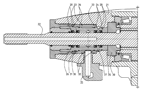
A rock drilling machine according to the invention is shown in Figures 3-5.
A front head 21 is manufactured from case-hardened steel or similar material
that has good
CA 02783004 2012-06-05
WO 2011/084093 PCT/SE2010/051339
mechanical properties. A shank adapter 22 and a stop ring 30 are arranged
within the front head 21 in conventional manner.
Flushing medium is led into the drilling machine through a rust-resistant
flush
connector 25 to a rust-resistant flush housing 26, through a rust-resistant
5 sheath 31 that has been pressed into the front head 21 and that surrounds
the
flush housing 26. "Rust-resistant" is here not to be interpreted as referring
solely
to stainless steel: it may be another rust-resistant material such as plastic.
The
flush connector 25 penetrates into the sheath 31 a certain distance in a hole
39
that has been arranged for this purpose. It may be arranged on certain rock
drilling machines such that it is possible to select whether it is desired to
place
the flush connector 25 on the right side or the left side of the rock drilling
machine, and in this case the sheath 31 has, naturally, two holes 39, see
Figure
5.
First seals 32 are arranged in grooves on the flush connector 25 in order to
create a seal between the flush connector 25 and the sheath 31. Second seals
33 are arranged in grooves on the sheath 31 in order to create a seal between
the sheath 31 and the front head 21. Third seals 34 are arranged in grooves on
the flush housing 26 in order to create a seal between the flush housing 26
and
the sheath 31, and also - possibly - the front head 21. This is carried out in
such
a manner that the flushing medium does not come into contact in normal
circumstances with the case-hardened steel, which is liable to attack by rust,
in
the front head 21. Furthermore, fourth seals 28 are arranged in the flush
housing in order to create a seal with the shank adapter 22.
The sheath 31 may have one of a number of appearances. It is appropriate, in
order to avoid mechanical loads, that the sheath 31 does not extend the full
distance to the stop ring 30, but rather that the front head 21 has a flange
35
between the sheath 31 and the stop ring 30, which flange absorbs the load from
the stop ring 30.
In order to be able to detect leaks, a front 36 and a rear 37 telltale hole
are
present into which flushing medium can emerge and thus indicate that a seal is
leaking. There is no major practical significance whether the sheath 31 is so
CA 02783004 2012-06-05
WO 2011/084093 PCT/SE2010/051339
6
long that it is present in the regions of the telltale holes 36, 37, or not.
If the
sheath 31 is so long that it is present in one of the regions of telltale
holes 36,
37, the sheath 31 must, naturally, have its own telltale hole 38 in order to
allow
leaking flushing medium to pass. In order to simplify mounting and demounting,
while at the same time ensuring that the sheath 31 is held in place in an
effective manner, it may be most simple if the sheath 31 is so long that it is
present in the region of the forward telltale hole 36, as shown in Figures 3-
5.
The flush connector 25 and the sheath 31 are thus not exposed to the high
impact forces from the stop ring 30 of the drilling machine and thus they do
not
need to be so mechanically strong. Also the flush housing 26 can be protected
from the impact forces through a part of the front head 21 coming in between
the flush housing 26 and the stop ring 30, or by having a small play between
the
flush housing 26 and the stop ring 30.
Since the flush connector 25 enters the sheath 31 but not the flush housing
26,
it is possible also to use without problems a flush housing 26 according to
the
example shown in Figures 3-5, in which the flush housing 26 is mounted and
demounted by means of rotation. However, the invention can of course be used
independently of the type of flush housing that is used.
The working of the rust-resistant material, which is more difficult, is
minimised
through the flush connector 25, the flush housing 26 and the sheath 21 being
relatively small fittings.
Thus, the purpose of the sheath 31 is to protect against rust solely where
this is
necessary, while the remainder of the front head 21 can be manufactured from
traditional case-hardened steel, which is cheaper, easier to work, and has
better
mechanical properties. The invention thus combines the positive properties of
case-hardened steel with the rust-protective effect of the rust-resistant
material.
A rock drilling machine as described above can be used as usual in a drill
rig.
The invention is, naturally, not limited to the example described above: it
can be
modified within the scope of the attached patent claims.