Language selection

Search

Patent 2783039 Summary

Third-party information liability

Some of the information on this Web page has been provided by external sources. The Government of Canada is not responsible for the accuracy, reliability or currency of the information supplied by external sources. Users wishing to rely upon this information should consult directly with the source of the information. Content provided by external sources is not subject to official languages, privacy and accessibility requirements.

Claims and Abstract availability

Any discrepancies in the text and image of the Claims and Abstract are due to differing posting times. Text of the Claims and Abstract are posted:

  • At the time the application is open to public inspection;
  • At the time of issue of the patent (grant).
(12) Patent: (11) CA 2783039
(54) English Title: BAKERY TRAY
(54) French Title: PLATEAU DE BOULANGERIE
Status: Deemed expired
Bibliographic Data
(51) International Patent Classification (IPC):
  • B65D 1/34 (2006.01)
(72) Inventors :
  • HASSELL, JON P. (United States of America)
(73) Owners :
  • REHRIG PACIFIC COMPANY (United States of America)
(71) Applicants :
  • REHRIG PACIFIC COMPANY (United States of America)
(74) Agent: MACRAE & CO.
(74) Associate agent:
(45) Issued: 2019-03-05
(22) Filed Date: 2012-07-09
(41) Open to Public Inspection: 2013-01-08
Examination requested: 2017-05-19
Availability of licence: N/A
(25) Language of filing: English

Patent Cooperation Treaty (PCT): No

(30) Application Priority Data:
Application No. Country/Territory Date
61/505,832 United States of America 2011-07-08

Abstracts

English Abstract

A bakery tray includes a base. A front wall extends upward from a front edge of the base. Side walls extend upward from side edges of the base. A rear wall extends upward from a rear edge of the base. The rear wall includes an inner panel portion and an outer lip portion that protrudes outward and then downward from an uppermost edge of the inner panel portion. A plurality of ribs connect the inner panel portion to the outer lip portion. In one feature, the plurality of ribs may include an increased concentration of the ribs in the center of the tray.


French Abstract

Un plateau de boulangerie comprend une base. Une paroi avant sétend vers le haut depuis un bord avant de la base. Des parois latérales sétendent vers le haut depuis les bords latéraux de la base. Une paroi arrière sétend vers le haut depuis un bord arrière de la base. La paroi arrière comprend une partie de panneau intérieur et une partie lèvre extérieure qui fait saillie vers lextérieur, puis vers le bas à partir dun bord supérieur de la partie de panneau intérieur. Une pluralité de nervures relient la partie de panneau intérieur à la partie de lèvre extérieure. Dans une caractéristique, la pluralité de nervures peuvent comprendre une concentration accrue de nervures au centre du plateau.

Claims

Note: Claims are shown in the official language in which they were submitted.

CLAIMS
1. A bakery tray comprising:
a base;
a front wall extending upward from the base;
side walls extending upward from the base;
a rear wall extending upward from the base, the rear wall includes an inner
panel
portion and an outer lip portion that protrudes outward and then downward from
an
uppermost edge of the inner panel portion;
a plurality of first ribs connecting the inner panel portion to the outer lip
portion,
wherein the plurality of ribs includes an increased concentration of the first
ribs in the center
of the tray;
a drag rail extending downward below the base from each side wall;
a plurality of corner pads extending downward from the base between the drag
rails,
wherein the corner pads extend downward further than the drag rails; and
a plurality of second ribs connecting the drag rails to the base.
2. The bakery tray of claim 1 wherein the rear wall is shorter than the
side walls.
3. The bakery tray of claim 2 wherein the front wall has a dropped portion
providing
access to the tray.
4. The bakery tray of claim 1 wherein the plurality of second ribs includes
an increased
concentration of the second ribs toward corners of the tray.

4

Description

Note: Descriptions are shown in the official language in which they were submitted.


BAKERY TRAY
BACKGROUND
Plastic injection molded bakery trays are well-known. The bakery trays include
a
base. Front, rear and side walls extend upward from respective edges of the
base. The front
wall and rear wall are typically shorter than the side walls. The front wall
may include a
dropped portion for increased access to the goods in the tray. The side walls
may be
configured to provide a first stacking height when oriented the same as a tray
on which it is
stacked and a second stacking height when oriented 180 degrees relative to the
tray on
which it is stacked.
SUMMARY
A bakery tray includes a base. A front wall extends upward from a front edge
of the
base. Side walls extend upward from side edges of the base. A rear wall
extends upward
from a rear edge of the base. The rear wall includes an inner panel portion
and an outer lip
portion that protrudes outward and then downward from an uppermost edge of the
inner
panel portion. A plurality of ribs connect the inner panel portion to the
outer lip portion.
According to one feature of the tray, the plurality of ribs may include an
increased
concentration of the ribs in the center of the tray.
According to another feature of the tray, a drag rail extends downward below
the
base from each side wall. A plurality of ribs connect the drag rails to the
base. The
plurality of ribs may include an increased concentration of the ribs toward
corners of the
tray.
According to another feature of the tray, a plurality of corner pads extend
downward
from the base between the drag rails. The corner pads may extend downward
further than
the drag rails to reduce wear on the drag rails.
1
CA 2783039 2018-09-05

CA 02783039 2012-07-09
BRIEF DESCRIPTION OF THE DRAWINGS
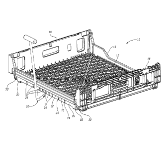
Figure 1 is a perspective view of a tray according to one embodiment of the
present
invention and hook that can be used to drag the tray.
Figure 2 is a rear view of the tray and hook of Figure 1.
Figure 3 shows the tray and hook of Figure 1 with the hook engaging the tray.
Figure 4 is a rear view of the tray and hook of Figure 3.
Figure 5 is a bottom perspective view of the tray and hook of Figure 3.
Figure 6 is a side, bottom perspective view of the tray of Figure 1.
Figure 7 is a top view of the tray of Figure 1.
Figure 8 is an enlarged view of one corner of the tray of Figure 7,
Figure 9 is a rear view of the tray of Figure 1.
Figure 10 is a bottom perspective view of the tray of Figure 1.
DETAILED DESCRIPTION
Referring to Figures 1 and 2, a bakery tray 10 includes a base 12. A front
wall 14
having a dropped portion or opening providing access to the tray 10, extends
upward from a
front edge of the base 12. Side walls 18 extend upward from side edges of the
base 12. A
rear wall 16 extends upward from a rear edge of the base 12. The side walls 14
are
approximately twice the height of the front wall 14 and rear wall 16. As
shown, the side
walls 14 may be configured to provide a first stacking height when oriented
the same as a
tray (not shown) on which it is stacked and a second stacking height when
oriented 180
degrees relative to the tray (not shown) on which it is stacked.
The rear wall 16 includes an inner panel portion 20 and an outer lip portion
22 that
protrudes outward and then downward from an uppermost edge of the inner panel
portion
20. Ribs 24 connect the inner panel portion 20 to the outer lip portion 22. In
the tray 10
according to a first feature of the present invention, there are an increased
number of ribs 24
in the center of the tray 10, so that there is an increased concentration
(approximately
double) of ribs 24 toward the center of the tray 10. For example, in the
example tray 10
shown, the center quarter (approximately) of the tray 10 includes two extra
ribs 24 while the
remainder of the ribs 24 along the rear wall 16 are equally spaced. This
increases the

strength of the outer lip portion 22 and its attachment to the inner panel
portion 20 in the
center area of the rear wall 16.
A drag rail 30 extends down below the base 12 from each side wall 18. A corner

pad 30 extends down from the base 12 in each comer of the base 12, inward of
the drag rails
20.
As shown in Figures 3-5, a hook 50 (e.g. "J-hook) can be inserted between the
outer
lip portion 22 and the inner panel portion 20. The tray 10 (or a stack of
trays 10) may be
moved (dragged) by the hook 50. Therefore all of the force is pulling on the
outer lip
portion 22. The additional ribs 24 in the center of the rear wall 16 reinforce
the outer lip
portion 22 and transmit the force more evenly to the inner panel portion 20
and to the base
12.
Figure 6 shows the underside of the base 12 of the tray 10. As shown, there
are an
increased number and concentration of short ribs 34 connecting the base 12 to
the drag rail
30 near the corners of the tray 10. These short ribs 34 provide additional
support when the
tray is placed on a floor chain conveyor running parallel to the length of the
tray 10.
Figure 7 is a top view of the tray 10. Figure 8 is an enlarged view of one
corner of
the tray of Figure 7, showing the increased number of short ribs 34 connecting
the base 12
to the drag rail 30 near the corners of the tray 10.
As shown in Figures 9 and 10, the corner pads 32 protrude downward from the
base
12 further than the drag rails 30 (for example, .03" more than the drag rails
30). As a result,
the tray 10 will be dragged on the floor on the corner pads 32 which will wear
before the
drag rails 30. Protecting the drag rails 30 should extend the life of the tray
10.
As is commonly known, the entire tray 10 is preferably injection molded as a
single-
piece of plastic.
In accordance with the provisions of the patent statutes and jurisprudence,
exemplary configurations described above are considered to represent a
preferred
embodiment of the invention. However, it should be noted that the invention
can be
practiced otherwise than as specifically illustrated and described without
departing from its
scope.
3
CA 2783039 2018-09-05

Representative Drawing
A single figure which represents the drawing illustrating the invention.
Administrative Status

For a clearer understanding of the status of the application/patent presented on this page, the site Disclaimer , as well as the definitions for Patent , Administrative Status , Maintenance Fee  and Payment History  should be consulted.

Administrative Status

Title Date
Forecasted Issue Date 2019-03-05
(22) Filed 2012-07-09
(41) Open to Public Inspection 2013-01-08
Examination Requested 2017-05-19
(45) Issued 2019-03-05
Deemed Expired 2020-08-31

Abandonment History

There is no abandonment history.

Payment History

Fee Type Anniversary Year Due Date Amount Paid Paid Date
Application Fee $400.00 2012-07-09
Maintenance Fee - Application - New Act 2 2014-07-09 $100.00 2014-06-09
Maintenance Fee - Application - New Act 3 2015-07-09 $100.00 2015-06-09
Maintenance Fee - Application - New Act 4 2016-07-11 $100.00 2016-06-08
Request for Examination $800.00 2017-05-19
Maintenance Fee - Application - New Act 5 2017-07-10 $200.00 2017-06-07
Maintenance Fee - Application - New Act 6 2018-07-09 $200.00 2018-06-07
Final Fee $300.00 2019-01-21
Maintenance Fee - Patent - New Act 7 2019-07-09 $200.00 2019-06-20
Owners on Record

Note: Records showing the ownership history in alphabetical order.

Current Owners on Record
REHRIG PACIFIC COMPANY
Past Owners on Record
None
Past Owners that do not appear in the "Owners on Record" listing will appear in other documentation within the application.
Documents

To view selected files, please enter reCAPTCHA code :


To view images, click a link in the Document Description column. To download the documents, select one or more checkboxes in the first column and then click the "Download Selected in PDF format (Zip Archive)" or the "Download Selected as Single PDF" button.

List of published and non-published patent-specific documents on the CPD .

If you have any difficulty accessing content, you can call the Client Service Centre at 1-866-997-1936 or send them an e-mail at CIPO Client Service Centre.


Document
Description 
Date
(yyyy-mm-dd) 
Number of pages   Size of Image (KB) 
Abstract 2012-07-09 1 14
Description 2012-07-09 3 134
Claims 2012-07-09 3 73
Cover Page 2013-01-15 1 26
Request for Examination 2017-05-19 1 26
Examiner Requisition 2018-04-10 4 225
Amendment 2018-09-05 16 663
Drawings 2018-09-05 10 486
Claims 2018-09-05 1 28
Description 2018-09-05 3 135
Final Fee 2019-01-21 1 27
Representative Drawing 2019-02-07 1 38
Cover Page 2019-02-07 1 68
Correspondence 2012-07-26 1 20
Assignment 2012-07-09 2 66
Correspondence 2012-09-25 2 39
Correspondence 2012-10-10 1 26
Correspondence 2012-10-17 2 41