Note: Descriptions are shown in the official language in which they were submitted.
CA 02783155 2012-06-06
WO 2011/071775
PCT/US2010/058931
PHACOEMULSIFICATION HAND PIECE WITH INTEGRATED
ASPIRATION PUMP
BACKGROUND OF THE INVENTION
The present invention relates to phacoemulsification surgery and more
particularly to a device that better regulates pressure experienced in the eye
during
cataract surgery.
The human eye functions to provide vision by transmitting light through a
clear outer portion called the cornea, and focusing the image by way of a
crystalline
lens onto a retina. The quality of the focused image depends on many factors
including the size and shape of the eye, and the transparency of the cornea
and the
lens. When age or disease causes the lens to become less transparent, vision
deteriorates because of the diminished light which can be transmitted to the
retina.
This deficiency in the lens of the eye is medically known as a cataract. An
accepted
treatment for this condition is surgical removal of the lens and replacement
of the lens
function by an artificial intraocular lens (IOL).
In the United States, the majority of cataractous lenses are removed by a
surgical technique called phacoemulsification. A typical surgical hand piece
suitable
for phacoemulsification procedures consists of an ultrasonically driven
phacoemulsification hand piece, an attached hollow cutting needle surrounded
by an
irrigating sleeve, and an electronic control console. The hand piece assembly
is
attached to the control console by an electric cable and flexible tubing.
Through the
electric cable, the console varies the power level transmitted by the hand
piece to the
attached cutting needle. The flexible tubing supplies irrigation fluid to the
surgical
site and draws aspiration fluid from the eye through the hand piece assembly.
The operative part in a typical hand piece is a centrally located, hollow
resonating bar or horn directly attached to a set of piezoelectric crystals.
The crystals
supply the required ultrasonic vibration needed to drive both the horn and the
attached
cutting needle during phacoemulsification, and are controlled by the console.
The
crystal/horn assembly is suspended within the hollow body or shell of the hand
piece
by flexible mountings. The hand piece body terminates in a reduced diameter
portion
or nosecone at the body's distal end. Typically, the nosecone is externally
threaded to
accept the hollow irrigation sleeve, which surrounds most of the length of the
cutting
needle. Likewise, the horn bore is internally threaded at its distal end to
receive the
CA 02783155 2012-06-06
WO 2011/071775
PCT/US2010/058931
external threads of the cutting tip. The irrigation sleeve also has an
internally threaded
bore that is screwed onto the external threads of the nosecone. The cutting
needle is
adjusted so that its tip projects only a predetermined amount past the open
end of the
irrigating sleeve.
During the phacoemulsification procedure, the tip of the cutting needle and
the
end of the irrigation sleeve are inserted into the anterior segment of the eye
through a
small incision in the outer tissue of the eye. The surgeon brings the tip of
the cutting
needle into contact with the lens of the eye, so that the vibrating tip
fragments the
lens. The resulting fragments are aspirated out of the eye through the
interior bore of
the cutting needle, along with irrigation solution provided to the eye during
the
procedure, and into a waste reservoir.
Throughout the procedure, irrigating fluid is pumped into the eye, passing
between the irrigation sleeve and the cutting needle and exiting into the eye
at the tip
of the irrigation sleeve and/or from one or more ports, or openings, cut into
the
irrigation sleeve near its end. This irrigating fluid is critical, as it
prevents the
collapse of the eye during the removal of the emulsified lens. The irrigating
fluid also
protects the eye tissues from the heat generated by the vibrating of the
ultrasonic
cutting needle. Furthermore, the irrigating fluid suspends the fragments of
the
emulsified lens for aspiration from the eye.
A common phenomenon during a phacoemulsification procedure arises from
the varying flow rates that occur throughout the surgical procedure. Varying
flow
rates result in varying pressure losses in the irrigation fluid path from the
irrigation
fluid supply to the eye, thus causing changes in pressure in the anterior
chamber (also
referred to as Intra-Ocular Pressure or TOP.) Higher flow rates result in
greater
pressure losses and lower IOP. As IOP lowers, the operating space within the
eye
diminishes.
Another common complication during the phacoemulsification process arises
from a blockage, or occlusion, of the aspirating needle. As the irrigation
fluid and
emulsified tissue is aspirated away from the interior of the eye through the
hollow
cutting needle, pieces of tissue that are larger than the diameter of the
needle's bore
may become clogged in the needle's tip. While the tip is clogged, vacuum
pressure
builds up within the tip. The resulting drop in pressure in the anterior
chamber in the
eye when the clog is removed is known as post-occlusion surge. This post-
occlusion
surge can, in some cases, cause a relatively large quantity of fluid and
tissue to be
2
CA 02783155 2012-06-06
WO 2011/071775
PCT/US2010/058931
aspirated out of the eye too quickly, potentially causing the eye to collapse
and/or
causing the lens capsule to be torn.
Various techniques, such as venting the aspiration line, have been designed to
reduce this surge. However, there remains a need for improved
phacoemulsification
devices that reduce post-occlusion surge as well as maintain a stable 10P
throughout
varying flow conditions.
3
CA 02783155 2016-04-12
SUMMARY OF THE INVENTION
Certain exemplary embodiments can provide an ophthalmic surgical hand piece
comprising: a driver coupled to a horn, the horn coupled to a needle; an
aspiration pump
integral with the hand piece, the aspiration pump located proximate to the
needle, the
aspiration pump comprising: a motor; a moveable member coupled to the motor;
and a
flexible length of aspiration line; and a rigid length of aspiration line
located between the
aspiration pump and the needle, wherein the moveable member engages the
flexible length of
aspiration line and wherein the moveable member is moveable at least one of
towards and
away from the flexible length of aspiration line to adjust a leakage amount
that alters a
vacuum pressure in the rigid length of aspiration line.
Certain exemplary embodiments can provide an ophthalmic surgical hand piece
comprising: a driver coupled to a horn, the horn coupled to a needle; an
aspiration pump
integral with the hand piece, the aspiration pump comprising: a motor; and a
shaft coupled to
the motor, the aspiration pump located proximate to the needle; a cartridge
coupled to the
aspiration pump; and a rigid length of aspiration line located between the
aspiration pump and
the needle, wherein the shaft engages the cartridge and wherein the shaft is
moveable at least
one of towards and away from the cartridge to adjust a leakage amount that
alters a vacuum
pressure in the rigid length of aspiration line.
Certain exemplary embodiments can provide an ophthalmic surgical hand piece
comprising: a driver coupled to a horn, the horn coupled to a needle; an
aspiration pump
integral with the hand piece, the aspiration pump comprising: a motor; and a
shaft operably
coupled to the motor, the shaft comprising a spiral structure; and a flexible
length of
aspiration line; and a rigid length of aspiration line located between the
aspiration pump and
the needle, wherein the spiral structure is adapted to press against the
flexible length of
aspiration line.
4
CA 02783155 2016-10-31
.
Certain exemplary embodiments can provide an ophthalmic surgical hand piece
comprising: a driver coupled to a horn, the horn coupled to a needle; an
aspiration pump
integral with the hand piece, the aspiration pump located in proximity to the
needle, the
aspiration pump comprising: a flexible tubing; a motor; and a shaft rotatably
coupled to the
motor and including a spiral structure configured to press against the
flexible tubing; and a
rigid length of aspiration line located between the aspiration pump and the
needle.
Certain exemplary embodiments can provide an ophthalmic surgical hand piece
comprising: a driver coupled to a horn, the horn coupled to a needle; an
aspiration pump
integral with the hand piece, the aspiration pump located in proximity to the
needle, the
aspiration pump comprising: a motor; and a shaft rotatably coupled to the
motor, the shaft
comprising a spiral structure; a removable cartridge coupled to the aspiration
pump, the
removable cartridge comprising: a tubing holder; and a flexible tubing held by
the tubing
holder, the flexible tubing located between the shaft and the tubing holder;
and a rigid length
of aspiration line located between the aspiration pump and the needle, wherein
the spiral
structure is configured to press against the length of flexible tubing.
In another embodiment consistent with the principles of the present invention,
the
present invention is an ophthalmic surgical hand piece comprising a driver
coupled to a horn,
the horn coupled to a needle an aspiration pump integral with the hand piece,
the aspiration
pump located close to the needle; and a rigid length of aspiration line
located between the
aspiration pump and the needle.
In another embodiment consistent with the principles of the present invention,
the
present invention is an ophthalmic surgical hand piece comprising a driver
coupled to a horn,
the horn coupled to a needle an aspiration pump integral with the hand piece,
the aspiration
pump located close to the needle; a disposable segment coupled to the
aspiration pump; and a
rigid length of aspiration line located between the aspiration pump and the
needle.
It is to be understood that both the foregoing general description and the
following
detailed description are exemplary and explanatory only and are intended to
provide further
explanation of the invention as claimed. The following description, as well as
the practice of
the invention, set forth and suggest additional advantages and purposes of the
invention.
4a
CA 02783155 2016-04-12
..
=.
BRIEF DESCRIPTION OF THE DRAWINGS
The accompanying drawings, which are incorporated in and constitute a part of
this
specification, illustrate several embodiments of the invention and together
with the
description, serve to explain the principles of the invention.
Figure 1 is a diagram of the components in the fluid path of a
phacoemulsification
system including a hand piece with an integrated aspiration pump according to
the principles
of the present invention.
Figure 2 is a block diagram of a phacoemulsification hand piece with an
integrated
aspiration pump according to the principles of the present invention.
Figure 3 is a block diagram of a phacoemulsification hand piece with an
integrated
aspiration pump according to the principles of the present invention.
4b
CA 02783155 2012-06-06
WO 2011/071775
PCT/US2010/058931
Figure 4 is a side view of a portion of a phacoemulsification hand piece with
an integrated aspiration pump according to the principles of the present
invention.
Figure 5 is a cross section view of a portion of a phacoemulsification hand
piece with an integrated aspiration pump according to the principles of the
present
invention.
Figure 6 is a side view of a removable cartridge for use with a
phacoemulsification hand piece with an integrated aspiration pump according to
the
principles of the present invention.
Figures 7 is a perspective view of a removable cartridge for use with a
phacoemulsification hand piece with an integrated aspiration pump according to
the
principles of the present invention.
DETAILED DESCRIPTION OF THE PREFERRED EMBODIMENTS
Reference is now made in detail to the exemplary embodiments of the
invention, examples of which are illustrated in the accompanying drawings.
Wherever possible, the same reference numbers are used throughout the drawings
to
refer to the same or like parts.
Figure 1 is a diagram of the components in the fluid path of a
phacoemulsification system including a hand piece with an integrated
aspiration pump
according to the principles of the present invention. Figure 1 depicts the
fluid path
through the eye 145 during cataract surgery. The components include an
irrigation
source 120, an optional irrigation pressure sensor 130, an optional irrigation
valve
135, an irrigation line 140, a hand piece 150, an aspiration line 155, an
optional
aspiration pressure sensor 160, an optional vent valve 165, a pump 170, a
reservoir
175 and a drain bag 180. The irrigation line 140 provides irrigation fluid to
the eye
145 during cataract surgery. The aspiration line 155 removes fluid and
emulsified
lens particles from the eye during cataract surgery.
When irrigation fluid exits irrigation source 120, it travels through
irrigation
line 140 and into the eye 145. An irrigation pressure sensor 130 measures the
pressure of the irrigation fluid in irrigation line 140. An optional
irrigation valve 135
5
CA 02783155 2012-06-06
WO 2011/071775
PCT/US2010/058931
is also provided for on/off control of irrigation. Irrigation pressure sensor
130 is
implemented by any of a number of commercially available fluid pressure
sensors.
A hand piece 150 is placed in relation to the eye 145 during a
phacoemulsification procedure. The hand piece 150 has a hollow needle (270 in
Figs.
2 & 3) that is ultrasonically vibrated in the eye to break up the diseased
lens. A sleeve
located around the needle provides irrigation fluid from irrigation line 140.
The
irrigation fluid passes through the space between the outside of the needle
and the
inside of the sleeve. Fluid and lens particles are aspirated through the
hollow needle.
In this manner, the interior passage of the hollow needle is fluidly coupled
to
aspiration line 155. Pump 170 draws the aspirated fluid from the eye 145. An
optional aspiration pressure sensor 160 measures the pressure in the
aspiration line.
An optional vent valve can be used to vent the vacuum created by pump 170. The
aspirated fluid passes through reservoir 175 and into drain bag 180.
Figure 2 is a block diagram of a phacoemulsification hand piece with an
integrated aspiration pump according to the principles of the present
invention. In
Figure 2, hand piece 150 comprises motor 210, shaft 220, removable cartridge
230,
optional aspiration pressure sensor 160, driver 250, horn 260, needle 270, and
aspiration line 280. Motor 210 rotates shaft 220. When the pump is in
operation,
removable cartridge 230 is held against shaft 220. Aspiration pressure sensor
160 is
located between removable cartridge 230 and the eye 145.
In Figure 2, the pump 170 comprises motor 210, shaft 220, and flexible tubing
in removable cartridge 230. In one embodiment of the present invention, shaft
220
has a spiral structure that presses against the flexible tubing in removable
cartridge
230. In this manner, a screw-type or scroll-type aspiration pump is
implemented with
motor 210, shaft 220, and flexible tubing in removable cartridge 230. This is
more
clearly shown and described in Figures 4 and 5. While pump 170 is described as
a
screw-type pump, other types of pumps may also be used.
Aspiration line 280 is fluidly coupled to removable cartridge 230. Aspiration
line also extends through or around drive 250, horn 260, and needle 270. A
lumen in
needle 270 is fluidly coupled to aspiration line 280. As described above,
fluid and
lens particles are aspirated through the lumen of needle 270. Aspiration pump
170
draws fluid and lens particles through the lumen of needle 270.
6
CA 02783155 2012-06-06
WO 2011/071775
PCT/US2010/058931
Driver 250 is typically an ultrasonic driver that produces ultrasonic
vibrations
in horn 260. Horn 260 is typically a mass of metal that is coupled to driver
250 and
needle 270. In this manner, vibrations produced by driver 250 are transferred
to horn
260 and to needle 270. Needle 270 is placed in the eye and vibrated to
fragment a
cataractous lens.
Aspiration pressure sensor 160 measures the aspiration pressure in aspiration
line 280. While shown as located between removable cartridge 230 and driver
250,
aspiration pressure sensor may be located at any location between pump 170 and
the
eye 145. Aspiration pressure sensor 160 may be implemented by any of a number
of
known pressure sensor devices.
Figure 3 is a block diagram of a phacoemulsification hand piece with an
integrated aspiration pump according to the principles of the present
invention. The
example of Figure 3 has the elements of Figure 2 plus an optional vent valve
165.
When optional vent valve 165 is present, it acts to provide a venting path for
the
aspiration pump 170. In this manner, pump 170 can be vented, for example, to
atmosphere when vent valve 165 is opened. As shown in Figure 3, aspiration
line 280
has two paths ¨ one path that goes through removable cartridge 230, and
another path
that goes around removable cartridge 230. This second path (that goes around
removable cartridge 230) and associated vent valve 165 may also be
incorporated into
removable cartridge 230. When vent valve 165 is opened, the aspiration or
vacuum
produced by pump 170 is decreased as a result of it being vented to
atmosphere.
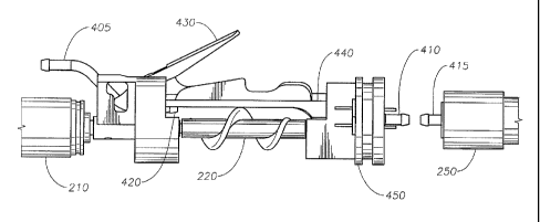
Figures 4 and 5 are side and cross section views, respectively, of a portion
of a
phacoemulsification hand piece with an integrated aspiration pump according to
the
principles of the present invention. Figures 4 and 5 more clearly show the
details of
one example of a removable cartridge 230 and pump 170. In the example shown,
removable cartridge 230 comprises aspiration line coupling 405, first tubing
coupling
420, tubing holder 440, and lever 430. These components are integrated into a
frame
as shown. Removable cartridge 230 can be removed from the remainder of the
hand
piece.
In the example of the removable cartridge shown in Figures 4 and 5, aspiration
line coupling 405 can be attached to aspiration tubing that is coupled to the
surgical
console. In this manner, aspiration line coupling 405 is near the end of the
hand piece
that is connected to the surgical console. A tube extends from aspiration line
coupling
7
CA 02783155 2012-06-06
WO 2011/071775
PCT/US2010/058931
405 to first tubing coupling 420. This tube is a part of the aspiration line
280 shown
in Figures 2 and 3.
Tubing holder 440 holds a flexible tube (not shown) that is located between
shaft 220 and tubing holder 440. Shaft 220 presses the flexible tubing against
tubing
holder 440. As shaft 220 rotates, the spiral protrusion on shaft 220 pumps
fluid
through the flexible tubing (thus implementing a screw-type or scroll-type
pump).
Tubing holder 440 is made of a rigid material that is suitable for holding
flexible
tubing. One end of the flexible tubing is fluidly coupled to first tubing
coupling 420,
and the other end of the flexible tubing is fluidly coupled to second tubing
coupling
425. In this manner, the flexible tubing is a part of the aspiration line 280.
Lever 430 operates to secure removable cartridge 230 to the remainder of the
hand piece. While shown as a lever, other mechanisms can be employed to secure
removable cartridge to the remainder of the hand piece.
Motor 210 is coupled to shaft 220 and serves to rotate shaft 220. Motor 210
can be controlled to control the movement of shaft 220 as more clearly
described
below. Motor 210 is typically a DC motor but can be any type of motor or
driver
suitable for rotating shaft 220.
In the example of Figures 4 and 5, a connector 450 connects the flexible
tubing held by tubing holder 440 to the hand piece coupling 415. Connector
coupling
410 interfaces with hand piece coupling 415 ¨ either directly or via another
part. In
this manner, the aspiration path passes through hand piece coupling 415,
connector
coupling 410, connector 450, second tubing coupling 425, the flexible tubing
held by
tubing holder 440, first tubing coupling 420 and aspiration line coupling 405.
Connector 450 is connected to an end of shaft 220. In this manner, connector
450,
shaft 220, and motor 210 (along with the frame that holds these parts) is
attached to
the driver 250 (which is coupled to the horn 260 and the needle 270).
The length of aspiration line between the pump and the eye (i.e. between
second tubing coupling 425 and needle 270) is minimal (on the order of
inches). In
addition, this length of aspiration line between the pump and the eye may be
non-
compliant (i.e. it can be rigid). Having a small length of non-compliant
tubing
between the pump 170 and the eye eliminates the surge associated with prior
art
systems.
8
CA 02783155 2012-06-06
WO 2011/071775
PCT/US2010/058931
In operation, motor 210 rotates shaft 220. A controller (not shown) controls
the operation of motor 210. In this manner, shaft 220 may be rotated at any
desired
speed to produce any desired vacuum. Further, shaft 220 may be stopped or
rotated in
an opposite direction if desired.. In this manner, motor 210 may be controlled
to
rotate shaft 220 in either direction. When rotated, shaft 220 draws fluid
through the
flexible tube and acts to pump the fluid through the aspiration line.
In another example, shaft 220 can be moved toward and away from tubing
holder 440. In this manner, the space between tubing holder 440 and shaft 220
can be
varied so that the flexible tubing can be pinched to different degrees between
shaft
220 and tubing holder 440. In other words, shaft 220 can pinch the flexible
tubing
held by tubing holder 440 very tightly to produce pumping action that does not
allow
for leakage. Alternatively, as shaft 220 is moved away from tubing holder 440,
the
flexible tubing is pinched less tightly thus leading to a leakage and less of
a vacuum
or pumping force. The position of shaft 220 with respect to tubing holder 440
can be
variably controlled to adjust the leakage through the flexible tubing, and in
turn adjust
the vacuum produced by the pump.
In another example (shown in Figure 3), the position of shaft 220 with respect
to tubing holder 440 can be fixed, and a vent valve 165 can be used to produce
leakage that adjusts the vacuum produced by the pump. In this manner, vent
valve
165 can be variably controlled to control the amount of vacuum that is present
in the
aspiration line (by controlling the amount of leakage through vent valve 165).
The control of aspiration vacuum can be based on a reading from aspiration
pressure sensor 160. Aspiration pressure sensor 160 is located between the
pump and
the eye. In this manner, aspiration pressure sensor 160 accurately reads the
pressure
conditions in the aspiration line very close to the eye. Such a reading can be
used to
precisely control the aspiration vacuum that is applied to the eye.
Figures 6 and 7 are side and perspective views, respectively, of a removable
cartridge for use with a phacoemulsification hand piece with an integrated
aspiration
pump according to the principles of the present invention. In the example of
Figures
6 and 7, the removable cartridge comprises aspiration line coupling, 405,
first tubing
coupling 420, tubing holder 440, lever 430, and opening 605. Opening 605
interfaces
with second tubing coupling 425 as shown in Figure 5. A piece of flexible
tubing is
located between first tubing coupling 420 and opening 605. The removable
cartridge
230 of Figures 6 and 7 can be reusable or disposable. In one example, the
removable
9
CA 02783155 2015-07-28
cartridge is reusable and the flexible tubing in disposable. In another
example, the removable
cartridge is disposable along with the flexible tubing.
The design of the present invention allows for the aspiration pump 170 to be
very
close to the eye 145. The distance between the aspiration pump 170 and the eye
145 can be
made to be very small - on the order of inches. Placing the aspiration pump
170 close to the
eye 145 allows for a very short length of aspiration line to be located
between the pump 170
and the eye 145. Moreover, the length of aspiration line located between the
pump 170 and
the eye 145 can be rigid (for example, it can be made of stainless steel).
This short length of
non-compliant material that makes up the aspiration line between the pump 170
and the eye
145 eliminates any surge effect associated with conventional
phacoemulsification systems.
In conventional phacoemulsification systems, the aspiration pump is located in
a
console. A relatively long length of flexible tubing (six feet or more) is
located between the
aspiration pump and the eye. This relatively long length of flexible tubing
has a lot of
compliance - it can stretch in response to changes in vacuum pressure. This
compliance
results in surges as previously described. By incorporating the aspiration
pump in the hand
piece (and placing it very close to the eye) and having a very short length of
non-compliant
tubing between the aspiration pump and the eye, these surges can be
eliminated, thus resulting
in a safer and more efficient surgery.
From the above, it may be appreciated that the present invention provides a
pressurized infusion system for phacoemulsification surgery. The present
invention provides
an irrigation squeeze band device that more precisely controls fluid pressure.
The present
invention is illustrated herein by example, and various modifications may be
made by a
person of ordinary skill in the art.
Other embodiments of the invention will be apparent to those skilled in the
art from
consideration of the specification and practice of the invention disclosed
herein. It is intended
that the specification and examples be considered as exemplary only, with the
scope of the
invention being indicated by the following claims.