Note: Descriptions are shown in the official language in which they were submitted.
CA 02783322 2012-06-06
PCT/AU2010/001639
Received 11 May 2011.
TITLE
A backstop and portable training system for a bat-and-ball game
TECHNICAL FIELD
The present invention relates to backstops and portable training systems for
bat
and ball games and in particular for cricket.
BACKGROUND
Playing nets are used for training in the playing of bat-and-ball games such
as
cricket. The purpose of playing nets is to act as a backstop - that is, to
stop the ball
travelling out of a designated playing area when the batter hits the ball,
thus
saving time and minimising the need for fielders. Therefore, playing nets are
useful
for training,-and for when playing "backyard", "street" or "beach" cricket -
when
typically there are few or no players to act as fielders to cover the playing
area.
Playing nets are typically supported by a fixed frame or posts so that the
assembled net stands well above the height of the player (e.g. cricket nets
typically
stand between 2.5 metres to 3 metres high).
Cricket nets consist of an elongate rectangular cricket pitch (the central
strip of the
playing area) into which two wickets are placed (one each at opposing ends of
the
cricket pitch) and a net surrounding three sides of the playing area, with the
bowling "end" left open. Similar playing nets exist In the form of baseball
batting
cages, for baseball,
Playing nets may be installed as a permanent structure on many ovals, cricket
centres, clubs and schools. "Portable" nets are available -for example, in the
form
of;
(a) foldable nets or practice cages that can be extended to their full length
for
use then folded away to save space;
1
Amended Sheet
IPEA/AU
r t
CA 02783322 2012-06-06
PCT/AU2010/001639
Received 11 May 2011
(b) a mobile net system (tunnel cage), in which the cage-style frame is
mounted on wheels for mobility.
However, these "portable" nets utilise a metal frame and are still substantial
in
structure (e.g. the resulting structure of the foldable cricket net stands at
over 2.5
metres in height), making them unsuitable for many home environments or as a
portable system to transport to a park.
The playing of ball games in the backyard or at a park or beach has a long
history In
many cultures. Various portable devices have been devised for playing ball
games
outdoors, including portable soccer nets. However, these devices are generally
not
suitable as backstops for bat-and-ball games like trlcket, baseball, softball,
tennis
or golf.
In soccer and basketball, the entire portable backstop (net or goalpost)
serves as a
target so that a ball landing anywhere within the area defined by the backstop
will
result in a score. Bat-and-ball games are different because the backstop may
serve
a dual purpose of stopping a ball from exiting the playing area behind the
batter,
but also presenting a target which, if hit, can cause the batter to get out.
For
example, in cricket hitting the wicket and causing the wicket to "break" will
cause
the batter to be 'but". Therefore, the playing of cricket involves protecting
the
wicket (target) behind the batter from balls bowled toward the batter.
Various portable bat-and-ball game targets are available, such as;
(a) US 3,986,719: a ball target for practising golf, including a rectangular
frame
mounted on unidirectional rockers and a mesh net secured within the
perimeter of the frame. The device Is configured so that when a golf ball is
driven into it, the force of impact causes the frame to rock backwards on
the unidirectional rockers (to tilt the top of the frame away from the
golfer),
(b) US 4,643,423: a pitching target including a self-supporting frame (A-
shaped
at each end) and a weighted, flexible screen (having a "strike zone"
2
Amended Sheet
IPEA/AU
CA 02783322 2012-06-06'
PCT/AU2010/001639
Received 11 May 2011
depicted on it) hanging from a crossbar at the top of the frame. A trough
positioned beneath the screen receives balls impacting on the screen and
falling downwardly therefrom; and
(c) US 4,148,555: a target scoring device formed of resilient material such as
a
net supported by elastic members and a frame, with a complex mechanical
trigger system that shows when the target has been hit;
(d) US 4,497,485: a baseball pitching target comprising a rectangular
peripheral frame staked to the ground and having a mesh backstop having
a centrally located insert that represents a target (e.g. with sight indicla
representing parts of the baseball environment such as a catcher's mitt).
Pitched balls that hit the strike zone are collected In a compartmentalised
ball-receiving bag. Balls that miss the strike zone are projected back
toward the pitcher by the action of the spring-mesh structure of the
backstop.
However, none of the above ball game targets Is suitable for use in cricket,
since
the configuration of target area within a strike zone, or the strike zone
generally,
are not appropriate for playing cricket. In baseball and softball, a ball is
pitched
toward a batter standing near the home plate or base but there is no need to
protect the home plate from the pitcher during pitching. US 3,986,719 is a
target
that sits in front of the batter and therefore is not suitable as a backstop
for games
such as cricket. Further, US 3,986,719 and US 4,643,423 are cumbersome to
assemble and bulky to transport. US 4,148,555 Involves a complex trigger
mechanism with various moving parts unsuitable for scoring in cricket as the
trigger target is tilted away from the player. US 4;497,485 does not Involve
moving
parts but the trampoline action of the backstop is not suitable when playing
ball
games such as cricket, particularly when cricket Is played with a tennis ball
or other
similar ball since the backstop will tend to sling the ball too far in a
direction away
from the target.
It would be useful to have a backstop suitable for use in bat-and-ball games
such as
cricket, and that is suitable for use in the typical home environment or as a
3
Amended Sheet
IPEAIAU
CA 02783322 2012-06-06
PCT/AU2010/001639
Received 11 May 2011
portable system to transport to a park or other outdoor playing area (e.g. for
playing cricket or backyard cricket - the latter also known as street cricket,
beach
cricket or gully cricket). Typically, backyard or street cricket Is played
using a ball
having a looped (Including fibrous) fabric surface such as a conventional
tennis ball
or arty similar Inflated ball having a fibrous felt, fabric, hair or wool
covered
surface. Tennis balls are commonly used in this context because they are less
likely
to inflict injuries than a cricket ball - they are also cheaper and more
readily
available than conventional leather-covered cricket balls and easier to hit
due to
different aerodynamics than cricket balls.
AU 2003100878 describes a cricket training apparatus for use In cricket nets.
The
apparatus includes shaped target devices to affix to the sidewall nets of a
cricket
net. While the apparatus is intended for use in improving player skills by
providing
a mechanism for players to visualise the correct placement of shots, it needs
to be
secured to a cricket net. Therefore, AU 2003100878 suffers a disadvantage in
that
its use is limited to circumstances in which a cricket net is readily
available.
AU2008101055 describes a portable training aid for use in practising the game
of
cricket. The training aid includes a target that is located in front of an
arrestor, the
arrestor including an opening and one or more walls behind the opening. Balls
that
miss the target will be stopped by the arrestor in an area behind the target,
while
balls that strike the target will rebound away from the training aid and
generally be
found in front of the target. However, AU2008101055 cannot differentiate
between balls that strike the target but still pass through the opening of the
arrestor and balls that miss the target and go directly through the opening of
the
arrestor. The former balls would result in the batter being "out" while the
latter
would not.
It would be useful to have a readily transportable and assembled backstop and
portable system for use in ball games such as cricket and that also provide
players
with a target, so as to improve player skills. It would be useful if the
target could
4
Amended Sheet
TUBA/ATr
CA 02783322 2012-06-06
PCT/AU2010/001639
Received 11 May 2011
provide a more reliable Indication of whether or not a target area
representing a
wicket or a fielder has been struck. None of the prior art devices above is
able to
provide an indication of when a target area has been struck by a bat - a
situation
that affects scoring which is unique to cricket - or when a scoring event such
as a
ball caught by a fielder has taken place.
It is an object of the present invention to provide an improved or alternative
backstop for a bat-and-ball game such as cricket, and Including one or more
target
areas on the backstop to improve player skill with both bat and ball.
DETAILED DESCRIPTION
According to an aspect of the invention there Is provided a bat-and-ball game
backstop for cricket including:
(a) a body made of suitable material to aid in preventing a ball
thrown towards a batter from exiting a playing area,
wherein:
I. the body comprises a central portion flanked by a side
portion on either side; and
if. each side portion is adjustable at an angle less than 180
'degrees relative to the central portion so that the
backstop is capable of sta nding substantially upright on a
supporting surface; and '
(b) one or more target areas on the body,
wherein each target area is configured to act as one portion of a
hook and loop fastener for attaching to a corresponding portion
of the hook and loop fastener on sporting equipment
S
Amended Sheet
IPEA/AU
CA 02783322 2012-06-06
PCT/AU2010/001639
Received 11 May 2011
such that when contact is made between:
I. a target area within the backstop, and
ii. said sporting equipment,
the target area fastens to said sporting equipment, thereby
Interfering with movement of said sporting equipment.
According to an aspect of the Invention there is provided a bat-and-ball
game backstop for cricket comprising;
(a) a'collapsible, self-supporting frame, wherein the self-supporting
frame is capable of self-supporting on a supporting surface, and
wherein the self-supporting frame is capable of self deploying to
a self-supporting state from a collapsed state;
(b) a body made of suitable material extending across a substantially
vertical portion of the self-supporting frame to aid in preventing a
ball thrown towards the backstop from exiting a playing area;
(c) one or more target areas on the body,
wherein each target area is configured to act as one portion of a
hook and loop fastener for attaching to a corresponding portion
of the hook and loop fastener an sporting equipment
such that when contact is made between:
' I. a target area within the backstop, and
Ii. said sporting equipment,
the target area fastens to said sporting equipment, thereby
interfering with movement of said sporting equipment.
6.
Amended Sheet
TPFA/AT 1
CA 02783322 2012-06-06
PCT/AU2010/001639
Received 11 May 2011
The invention thus provides a backstop for a bat-and-ball game such as
backyard
cricket, including one or more target areas on the backstop for Improving
player
skills. The invention overcomes the problems of existing backstops, which are
generally not suited for backyard cricket or too cumbersome and bulky for most
home environments or for transportation to a park or other outdoor playing
area.
For a better understanding of the Invention and to show how it may be
performed,
a preferred embodiment will.now be described, by way of non-limiting example
only, with reference to the accompanying drawings and example.
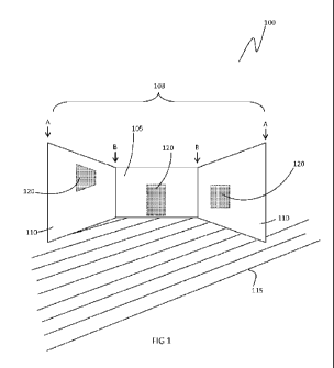
FIGURE 1 is a front view of one arrangement of a preferred embodiment of a
backstop for a bat-and-ball game according to the invention.
FIGURE 2 is a top view of the embodiment shown in Figure 1.
FIGURE 3 is a front view of another embodiment of a backstop for a bat-and-
ball
game according to the invention, showing securing means for retaining the
backstop in a substantially upright state during game play. Securing means are
shown at each end of the backstop and, as shown in ghost, Intermediate to the
ends.
FIGURE 4 Is a front view of another arrangement of the embodiment shown in
Figure 1.
FIGURE 5 shows two view of exemplary sporting equipment in the form of a ball
suitable for use with the backstop shown In any of the preceding Figures.
FIGURE 5A Is a front view of a conventional tennis ball or other similar
fibrous or
felt covered ball.
7
'Amended Sheet
iPFereIT
CA 02783322 2012-06-06
PCT/AU2010/001639
Received 11 May 2011
Figure 5B Is a perspective view of a modified ball (e.g. a cricket ball or
rubber ball)
with a portion of looped fabric for use with a target area providing
corresponding
hooked fabric.
Figure 6 Is a back view of exemplary sporting equipment in the form of a
cricket
bat suitable for use with the backstop shown in any of the preceding Figures.
Figure 7 shows views of an embodiment of an Independent target area according
to the invention. in this embodiment, the independent target area is capable
of
functioning Independently as a backstop or portable training system for a ball
game such as cricket. Figure 7A is a front view of an independent target area
showing an exemplary arrangement of patches or strips of hook and loop
fastener.
If the Independent target area is to be used as a fielder, the arrangement of
hook
and loop fastener may differ.
Figure 7B is a perspective view of the embodiment in Figure 7A, shown from the
back and demonstrating an exemplary support means,
Figure 7C Is the Independent target area of Figure 7A showing a different
exemplary support means than that of Figure 7B.
Figure 7D is a front view of the independent target area of Figure 7C,
Figure 7E Is a side view of Figure 7D, showing detail of the "bend" or elbow
of the
stand or frame.
Figure 7F is a side view of the independent target area of Figure 7C, showing
detail
of a holding mechanism to hold material in place on the stand or-frame of the
Independent target area, to prevent the material sliding In an upward
direction
from the ground.
Preferred embodiments of the backstop
The invention provides a new or alternative backstop for a bat-and-ball game
such
as cricket, including one or more target areas on the backstop for improving
player
g
Amended Sheet
iPPA/Aii
CA 02783322 2012-06-06
PCT/AU2010/001639
Received 11 May 2011
skills. The invention overcomes the problems of existing backstops and
portable
target devices, which are generally not suited for cricket or too cumbersome
and
bulky for most home environments or for transportation to a park or other
outdoor playing space.
TO Referring to Figure 1, a preferred embodiment of the backstop 100 is
illustrated.
The preferred embodiment 100 Includes:
(a) a body 103 made of suitable material to aid In preventing a ball thrown
towards a batter from exiting a playing area; and
(b) one or more target areas (depicted by the shaded areas labelled 120) on
the body 103.
The backstop Is suitable for assembly on grass, sand or around a concrete
cricket
pitch and enables cricket to be played without the need for fielders. The
target
areas provide player feedback and enable scoring without relying on visual
assessment, complex scoring devices or collection means such as a ball pocket
or
bag, which are inconvenient to use when there is a small number of players
because it interrupts game play.
The body
The body 103 is made of material such as a polyester or nylon material (e.g.
trilobal, shade cloth) or other material suitable for heavy duty or sporting
use and
relatively resistant to damage from contact with the hooked fabric element of
hook and loop fasteners.
In the preferred embodiment 100, the body 103 includes a central portion 105
with a side 'portion 110 on either side. The body may be made from continuous
or
discrete, adjoining portions. In one arrangement, the portions of the
preferred
embodiment are configured as shown in Figure 1. In an alternative arrangement,
the portions of the preferred embodiment are configured so. that the body
takes
the form of an arc (see Figure 4).
9
Amended Sheet
IPEAJAI I
t F '
CA 02783322 2012-06-06
PCT/AU2010/001639
Received 11 May 2011
The backstop 100 is configured so that it is able to be self supporting in an
upright
state (i.e. substantially perpendicular to a supporting surface such as the
ground
115 - as shown In Figure 1). The backstop 100 Is capable of being self
supporting
by virtue of!
(a) the relative positioning of the side portions in relation to the central
portion. As shown in the arrangement of the preferred embodiment shown
In Figure 1, the side portions 110 of the body 103 -are able to be positioned
on an angle relative to the central portion 105. In the arc arrangement
showing in Figure 4, the angle of curvature of the side portions relative to
the angle of curvature of the central portion achieves the same result as
the angled arrangement between side and central portions of the
embodiment shown in Figure 1. The side portions are delineated from the
central portion in the arc. arrangement shown in Figure 4 by dashed lines;
however, as for the arrangement in Figure 1 these portions may be
continuous or discrete adjoining portions; and,
(b) the inclusion of attachment means on the body. The attachment means
provide the ability to attach the backstop to support means such as battens
(not shown in Figure 1). The support means enhance the structural rigidity
of the backstop 100.
The positions of the side portions 110 relative to the central portion 105 of
the
embodiment In Figure 1 are better seen In Figure 2, which shows a top view of
the
preferred embodiment of the backstop 100. The angle between the side portions
110 and the central portion 105 of the body 103 is depicted by the letter X.
When
measured from the front of the backstop (that is, the surface of the backstop
facing toward the playing area In which the batter and bowler are positioned),
the
angle is less than 180 0, preferably between around 90 and 1556, and Ideally
around 135 . The ability to adjust the angle enables the backstop to be
adapted for
use in a range of locations - e.g. on different types of supporting surface
such as
on grass or sand, or configured around a concrete cricket pitch.
Amended Sheet
iPPA/AIJ
CA 02783322 2012-06-06
PCT/AU2010/001639
Received 11 May 2011
The support means may be any suitable elongate shaped solid material such as a
batten, post, pole, pipe, guide or other (such as wood, fibreglass, metal
(e.g.
aluminium), rigid plastic, rubber, etc). In the preferred embodiment, the
backstop
is appropriately attached to support means which provide.the required
structural
rigidity to assist in retaining the backstop 100 in an upright state. The
support
means also act as pivot points about which to angle the side portions 110
relative
to the central portion 105. in this way, the support means act to define the
side
perimeters of each portion of the backstop 100.
For example, as illustrated in Figure 1, the body of the backstop is attached
to
support means (such as a batten) at each of its free ends (at the points
marked A)
and pivoted around the support means (e.g.batten) at each point of inflexion
(i.e.
where the central portion meets a side portion - see the points marked B). The
attachment means can be any suitable means for attaching the support means to
the body, including reversible attachment. means (e.g. ties, strips of hook
and look
fastener attached to the body, channels on the body for receiving the support
means) and/or permanent attachment means such as glue, rivets and the like.
In one arrangement, the support means sit on the ground. In another
arrangement, the support means (e.g. battens) are able to be partially
Inserted
into the supporting surface 115 (e.g. lawn or sand) to further enhance
structural
rigidity.
in the arc arrangement, there may be additional support means such as battens
to
provide structural rigidity to the body along its curvature, inserted into
channels
along the curvature of the body (indicated in ghost by the item labelled 170).
Target area(s)
it
Amended Sheet
IPEA/AU
1 r
CA 02783322 2012-06-06
PCT/AU2010/001639
Received 11 May 2011
The preferred embodiment also includes one or more target areas on the body.
These are represented as the shaded areas labelled 120 in Figure 1, which are
illustrated by way of example only.
Each target area 120 provides one portion of a hook and loop fastener
(exemplary
. arrangements are depicted in Figure 4) so that when contact is made between
a
target area and sporting equipment bearing the corresponding portion of the
hook
and loop fastener, the sporting equipment Is capable of fastening to the
target
area. This corresponds to a scoring event (e.g. a caught ball or a wicket
being
knocked over) and provides player feedback during use.
For example, the target area may provide a hooked fabric surface having one or
more hooks capable of hooking on to one or more loops of a looped (Including
fibrous) fabric surface. Thus the target area is capable of attaching to
sporting
equipment having a looped (including fibrous) fabric surface upon contact,
such as
a tennis ball or other ball with a similar surface, or a modified cricket bat
having a
strip of looped fibrous fabric attached to back of the bat. conversely, the
target
area may be configured to act as the loop portion, capable of attaching to
sporting
equipment bearing a corresponding hook portion,
In this way, each target area is configured to act as a portion of a hook and
loop
fastener, while a tennis or other sporting equipment with a suitable surface
provides the corresponding portion, for fastening the sporting equipment to a
target area within the backstop when contact Is made between the target area
and
the sporting equipment. The fastening of sporting equIpment to the target area
corresponds to a scoring event.
For example, a tennis ball 180 (Figure 5A) or a modified ball 190 (Figure 5B)
of any
kind (e.g. cricket, leather, rubber or plastic) covered with a strip of one
portion of a
hook and loop fastener"() bowled toward a batter In the playing area that
strikes a
target area behind the batter will fasten to that target area. In the
preferred
12
Amended Sheet
iPEA/AU
CA 02783322 2012-06-06
PCT/AU2010/001639
Received 11 May 2011
embodiment, at least one target area represents a wicket behind the batter
(e.g.
the target area has the appearance of a wicket and includes strips of hook and
loop
fastener positioned along the parts of the wicket that represent the stumps
and
balls). A ball fastened to the target area representing the wicket Indicates
that the
wicket has been hit by the bowled ball. A ball struck by the batter and
fastened to
the target area representing the wicket also indicates that the wicket has
been hit
by the struck ball.
Similarly, a modified cricket bat 200 (Figure 6) or other similar hitting
apparatus
200 having a strip of, say, looped fabric surface attached, say to the tip or
back of
the bat, which fastens to the hooked (corresponding) fabric surface of the
target
area representing a wicket indicates that the batter has struck the wicket
with the
bat. In all these examples, the sporting equipment fastened to the part of the
target area representing a wicket indicates that the batter is `but".
One or more target areas are positioned on the body of the backstop so as to
represent (including taking on the appearance of) one or more components of
the
playing area (e.g. a wicket, a fielder, a base, net or fence). Contact between
a
target area and the sporting equipment (as corresponding portions of a hook
and
loop fastener) Interferes with movement of the sporting equipment. This
Inteference with movement (e.g. fastening of a ball to a target area
representing a
wicket) provides feedback to a player during game play, training or practice,
by
simulating a scoring event.
in some arrangements of the preferred embodiment, one or more target areas are
.30 included in addition to the wicket. These additional target areas
represent fielders.
A struck or bowled ball that fastens to one of these additional target areas
Indicates a ball caught by a fielder.
The target areas are attached to the body of the backstop, say by stitching,
adhesive or other suitable attachment means. In some arrangements, the
13
Amended Sheet
iPFA/A11
CA 02783322 2012-06-06
PCT/AU2010/001639
Received 11 May 2011
attachment means are reversible (e.g. zippers, buttons, press studs, or hook
and
loop fasteners) to enable one or more target areas to be removed or added, for
adjusting the level of difficulty of game play (e.g. the inclusion of more
fielders
Increases the chances of being caught out). Reversible attachment means also
enable fielders to be 'portable' so that they can be repositioned on the field
represented by the body of the backstop as desired.
Alternative embodiments
Figure 3 shows an alternative embodiment of the backstop 130 which includes
channels 140 for receiving support means such as battens 150 into the backstop
so
that the backstop is securely attached to the support means. The channels run
along the side perimeters of each portion in a direction such that when In use
the
channels are substantially perpendicular to the supporting surface (e.g. the
ground).
The support means can be retained within the channels during transport,
storage
and use, thereby assisting to reduce the steps involved in assembly and
disassembly.
The support means 150 serve the same purpose as the support means as described
In the preceding discussion - namely, to provide structural rigidity and
support for
retaining the backstop In an upright state and to serve as pivot points about
which
to angle the side portions relative to the central portion.
The embodiment 130 also Includes securing means 160 for further securing the
backstop to the supporting surface such that that the backstop is retained in
a
substantially upright state during game play. The securing means 160 may be
any
suitable means for securing the backstop to the ground or other supporting
surface
during use such as:
14
Amended Sheet ;
TDPA/ATT
CA 02783322 2012-06-06
PCT/AU2010/001639
Received 11 May 2011
(a) one or more guy ropes, each guy rope having opposing ends, one end being
attached to the body such as a partof the body at or near the support
means 150; and
(b) one or more pegs, each peg securing a guy rope to the supporting surface,
such that tension on the ropes secures the backstop to the supporting surface
in a
substantially upright state during use.
Assembly of the embodiment 130 thus involves the step of using securing means
such as guy ropes and peg assemblies to secure the backstop to the ground in a
substantially upright state. For example, the embodiment 130 includes at least
one
guy rope attached to a batten or post at each free and of the backstop 130.
Preferably, there are two guy ropes at each free end, splayed from each other
and
angled away from the backstop as they travel toward the ground -as illustrated
in
Figure 3. A further guy rope secures each end of the central portion,
extending
from the top of a batten down to the ground at the back of the backstop (i.e.
the
surface of the backstop facing away from the playing area). Each guy rope is
attached to the ground by a peg; stake, spike or other suitable retaining
means for
securing the guy rope in position.
In experiments by the Inventor, this embodiment 130 Is capable of withstanding
the rigours of outdoor use even in windy conditions. This embodiment can also
he
left assembled, say in the backyard, for several weeks and will be maintained
in a
substantially upright state.
In yet another embodiment (not Illustrated), the backstop Is made of a
printable
textile upon which is printed a wicket and one or more fielders. The wicket
and
fielder(s) represent one or more target areas, each of which will have
attached to It
a hooked fabric surface to enable fastening of sporting equipment having a
looped
fabric surface - as described above. Other details may also be printed on the
backstop. The printed backstop assists in simulating play as though on a
sports
field.
Amended Sheet
TPPA/ATT
CA 02783322 2012-06-06
PCT/AU2010/001639
Received 11. May 2011
In some arrangements, the target areas may include auditory feedback means
such
as a sound emitting device so that a sound is emitted when the target area is
struck. An example is the sound of a ball or bat striking a wicket. This
provides
players with auditory feedback to further assist in improving player skill and
to
enhance the game experience.
A specific example of a backstop for use In.backyard cricket is provided
below.
EXAMPLE 1
A body made from three continuous portions, each portion being
approximately 1200 mm high (although up to 1800 mm Is also suitable)
and about 1500 mm wide. Four channels (pole pockets) are located on
the body - one at each free end of the backstop and one at each end of
the central portion. A readily available rigid plastic tubular post is
inserted into each channel and pushed into the ground. The posts
extend a few centimetres higher than the channel - so that guy ropes
can be wound around the top of the post, extending down to the
ground at an angle. Tent pegs are used to secure the guy ropes to the
lawn.
The body may be made from polyester printed continuously in one
sheet to represent a cricket pitch on an oval. Alternatively, the body can
be printed In sections and joined, such as at the channels (pole pockets).
The print Includes a wicket keeper, and, say two, fielders, plus target
areas representing the wicket and a hand of each fielder.
Assembly takes around a few minutes with two people (the minimum
required to play backyard cricket).
16
Amended Sheet
IPEA/AU
CA 02783322 2012-06-06
PCT/AU2010/001639,
Received 11 May 2011
Preferred embodiments of a portable training system.
in an embodiment, the invention further provides a portable training system
for a.
bat and ball game includes a backstop 100 (see Figures 1-4) as described
earlier in
this document and any suitable sporting equipment that provides a portion of a
hook and loop fastener that corresponds with another portion of the hook and
loop fastener on one or more target areas an the backstop.
Such sporting equipment includes:
(a). a conventional tennis or similar ball 180 (Figure SA) having a fibrous
felt, fabric,
hair or wool covered surface;
(b) a modified ball 190 (Figure 58) of any kind (e.g. cricket, leather, rubber
or.piastic)
covered with a strip of one portion of a hook and loop fastener;
(c) a modified bat 200 (Figure 6), racquet or similar sporting equipment
covered with
a strip or patch of one portion of a hook and loop fastener at an appropriate
position (e.g. the tip or back of the bat - see Figure 6).
In another embodiment, the portable training system includes one or more
target
areas discrete or independent from the body. These "independent" target areas
210 (Figure 7) represent (typically In appearance as well as by positioning) a
wicket
keeper, fielder or other component of the playing area, such as a fence, and
can be
positioned separately from the backstop. This allows the size of the playing
area
and/or the difficulty of play to be adjusted further than by adjustment of
target
areas on the backstop alone.
The Independent target areas share most of the features as target areas
positioned
on the backstop described earlier in this document, other than being separate
from the backstop. Importantly, independent target areas include strips or
patches
of hook and loop fastener (an example Is depicted in Figure 7A).so that the
independent target areas are able also to function as the corresponding
portions
of hook and loop fastener to suitable sporting equipment.
17
Amended Sheet
IPEA/AU
CA 02783322 2012-06-06
PCT/AU2010/001639
Received 11 May 2011
The independent target areas 210 may be free standing (achieved by any
suitable
support means) and easily moveable. Examples of suitable support means 220
(Figure 7B) for independent target areas include:
(a) a stake or peg for use on a soft supporting surface;
(b) a stand or frame such as a bent oval-shaped stand (as shown in Figure 7B).
The
stand or frame may be any suitable shape that can be bent so that the stand Is
self-supporting. Suitable shapes include oval or substantially oval,
elliptical,
circular, or a square or rectangle with rounded or squared corners.
Figure 7A Is a front view of an independent target area 210 showing. an
exemplary
arrangement 120 of patches or strips of hook and loop fastener on material
112,
the material 112 forming the body of . The arrangement of hook and loop
fastener
120 on the material 112 may differ, depending on use - for example, if the.
independent target area 210 Is to be used as a fielder rather than a wicket
keeper.
The material 112 of the Independent target area 210 is shaped to sit on the
frame
117,.or stand, in analogous fashion to the body of the backstop 100 of Figures
1, 3
and 4 (see Item 110 in those figures). In other words, the material 112. Is
capable of
preventing a ball thrown towards the frame 117 from travelling through or
between the legs (117a, 117b)'of the frame 117. If the independent target area
210 Is being used In the wicket keeper's position, the independent target area
210
Is thereby capable of functioning as a backstop.
Figure 7B Is a perspective view of the independent target area of Figure 7A,
shown
from the back and demonstrating an exemplary support means 220. Figure 7C is
the Independent target area ' 210 of Figure 7A with an alternative exemplary
support means than that of Figure 7B.
Referring to Figures 7C and 7D, the material 112 of the Independent target
area
210 is secured to the upper portion of a stand or frame 117, the frame 117 and
material 112 together functioning as self-supporting support means 220 (Figure
7D). The upper portion is the portion of the stand. that is substantially
18
Amended Sheet
IPEA/AU
CA 02783322 2012-06-06
PCT/AU2010/001639
Received 11 May 2011
perpendicular to the supporting surface (e.g. ground or floor). The lower
portion of
the stand lies along the supporting surface.
The material 112 Is fitted to the frame 117 so that It Is stretched between
leg 117a
and 117b to hold leg 117a and leg 117b in the desired shape and to resist
movement of the legs outward (that is, away from the midline). This assists in
retaining the independent target area 210 in a substantially vertical
position. The
material 112 can be secured to the frame 117 by any suitable means such as by
threading the legs 117a and 117b through a pocket seam116 that sits around the
periphery of the frame. The Inner edge of the pocket seam 116 Is delineated in
Figure 7D by a dotted line.
A piece or flap of skirting material 124 (Figure 7D) is attached (or
attachable) to the
lower edge of the material 112. This assists to prevent balls from rolling
under the
material 112 during play, into the area bounded by the legs of the frame 117.
The
skirting material can also be weighed down by placing a weight (e.g. hand
weight, a
rock, brick, sandbag or any other suitably weighted item) on the skirting
material
(e.g. on far sides of the flap). This will facilitate blockage of movement of
balls
under the material 112 and can also assist in weighing down the independent
target area backstop 210 in windy conditions.
The shape of the frame 117 also assists with the self-supporting nature of the
independent target area 210 of the embodiment shown in Figure 70. The frame
117 Is bent to form an elbow 118 (shown In ghost) at the point it makes
contact
with a supporting surface (e.g. hard ground). The frame 117 may be formed from
a
single loop of.rod-like material (e.g. fibreglass, steel rod, carbon fibre
rod, or a
resiliently deformable material such as spring steel connected at its free
ends to
form a closed loop, bent at the circumference to form an elbow) or two or more
interconnecting rods.
19
Amended Sheet
TDRA/AIT
CA 02783322 2012-06-06
PCT/AU2010/001639
Received 11 May 2011
In an embodiment, the Independent target area 210 Is a popr-up backstop,
moveable between a collapsed state and a self-supporting state. This is
achieved
by having a frame 117 made of resiliently compressible material, which is
collapsed
Into the collapsed state by twisting the frame 117 to form two or more
substantially concentric loops. The concentric loops are capable of sitting
10. substantially flat one on top of the other and of being secured together
(e.g. by
applying a compressive force such as by wrapping a strip of velcro wrapped
around
the a common point along the circumference of the concentric loops, or by
insertion Into a carry bag or sleeve). In this embodiment, the Independent
target
area self deploys to a shape ready for use (i.e. a self-supporting state) when
the
frame is taken out of its carry bag or sleeve, or when the compressive force
is
removed from the common circumference of the concentric loops. This Is
analogous to deployment of a self-erecting sunshade or pop-up tent.
The elbow 118 may be covered with a protective sleeve 119 to further assist in
retaining the bent shape of the frame 117.
Figure 7E is a side view of Figure 7D, showing detail of the "bend" or elbow
of the
stand or frame. The frame 117 is shown in ghost. At the upper portion of the
frame
117, the bottom edge of material 112 can be seen. The inner edge of the pocket
seam 116 is represented by the dotted line. The elbow forms an acute angle
(marked X In Figure 7E). This further assists the stand or frame 117 to be
self-
supporting on the ground or floor.
A holding mechanism 121 assists to prevent the material is prevented from
riding
upwards upon the frame 117. In an exemplary arrangement, the holding
mechanism 121 comprises a tail 122 extending from the lower edge of the
material
112 towards the ground. The tall 122 may be an elongate or strap-like piece of
any
suitable material that extends from the material 112 of the Independent target
area 210 towards the elbow 118.
Amended Sheet
TOV A /ATT
= f CA 02783322 2012-06-06
PCT/AU2010/001639
Received 11 May 2011
In Figures 7E and 7F, an exemplary arrangement of the holding mechanism 121 is
depicted. A tail 122 is secured to the lower corner edge of the material 112
and
extends long the frame 117 towards the elbow 118. The tall 121 Is secured to
the
frame 117 around the elbow area by passing It through a holding sleeve 123
then
crimping the holding sleeve 123 once the tall 122 Is In position, to prevent
movement of the tail 122 out of the holding sleeve 123. passing through.
The holding sleeve 123 sits on the frame 117 between the elbow 118 and the
material 112. As seen In Figure 7F, the holding sleeve 123 can be slid down
along
each leg of the frame 117 to secure the lower edge of the material 112
proximate
to theelbow 118.
The tall 122 is held to position on the frame 117 by crimping the holding
sleeve
123, by using a holding sleeve made of resilient material, glue or any other
suitable
securing means.
The independent target areas 210. can be used as an alternative to the full
backstop (see item 100 of Figures 1 and 4) if the playing area is not large
enough or
if the supporting surface (e.g. ground) is not suitable for inserting the
securing
means of the backstop.ln this embodiment, the Independent target area 210 is
capable of functioning independently as a backstop or portable training system
for
a ball game such as cricket.
Thus In an embodiment, the backstop /training system comprises one or more
Independent target areas 210. This provides flexibility for use of the
Independent
target area 210 / portable training system indoors, on a hard surface, or when
space is limited. It also provides flexibility for the training system to
Include a
plurality of Independent target areas, setup in a limited space - such as
for.crlcket
clubs or schools when using multiple training systems simultaneously at a
single
venue may be desirable, or simply to allow different arrangements of a desired
number of independent target areas for training purposes.
21
Amended Sheet
TPPA/All
CA 02783322 2012-06-06
PCT/AU2010/001639
Received 11 May 2011
An advantage of the preferred embodiment of the backstop and portable training
system is that they provide a portable and simple to assemble backstop for use
in
bat-and-ball games such as cricket that Is suitable for use In the typical
home
environment or as a portable system to transport to a park or other outdoor
playing area (e.g. for playing backyard cricket, or for training in the school
or club
environments). The body of the backstop can be rolled up for storage and
transportation (e.g. In a bag), then unrolled for assembly. This is useful for
environments such as schools and clubs in which it may be necessary to have
several teams playing simultaneously.
A further advantage of the preferred embodiments Is that they provide one or
more target areas for improving player skill with both bat and ball. This is
because
a clear Indicator of a scoring event is provided when sporting equipment
(Including
balls and bats) strikes a target area, removing the need to rely on visual
assessment, complex scoring devices, devices such as ball bags or pockets that
capture balls (which are Inconvenient to use when there Is a small number of
players and play must be interrupted to retrieve a ball from a pocket or bag
behind
the backstop). This makes the preferred embodiments useful as a training aid,
whether at home or in a school or club environment (e.g. when used as a
sporting
or physical education activity).
The invention provides a backstop for a bat-and-ball game such as cricket, and
in
particular backyard cricket, Including one or more target areas on the
backstop for
Improving player skills. The invention further provides a portable training
system
for a bat and ball game, including a backstop, one or more independent
training
areas and sporting equipment. However, It will be appreciated that the
invention is
not restricted to particular embodiments or applications described herein.
22
Amended Sheet
IPEA/AU