Note: Descriptions are shown in the official language in which they were submitted.
CA 02783471 2012-06-05
WO 2011/075629
PCT/US2010/060979
APPLICATION FOR PATENT
INVENTOR: CHARLES ELMER BELL; HAROLD DEAN
BRANNON
TITLE: METHOD OF FRACTURING SUBTERRANEAN
FORMATIONS WITH CROSSLINKED FLUID
SPECIFICATION
Field of the Invention
[0001] The
invention relates to a method of fracturing a subterranean formation
with an aqueous fluid which contains a hydratable polymer and a crosslinking
agent
wherein the apparent viscosity of the fluid decreases distally from the
entrance site
of the reservoir.
Background of the Invention
[0002]
Hydraulic fracturing often requires the use of well treating materials
capable of enhancing the production of fluids and natural gas from low
permeability formations. In a typical hydraulic fracturing treatment, a
fracturing
treatment fluid containing a solid proppant is injected into the formation at
a
pressure sufficiently high enough to cause the formation or enlargement of
fractures in the reservoir. The fractures radiate outwardly from the wellbore,
typically from a few meters to hundreds of meters, and extend the surface area
from
which oil or gas drains into the well. The proppant is deposited in the
fracture,
where it remains after the treatment is completed. After deposition, the
proppant
serves to prevent closure of the fracture and to form a conductive channel
extending from the wellbore into the formation being treated. As such, the
proppant enhances the ability of fluids or natural gas to migrate from the
formation
to the wellbore through the fracture.
[0003] Many
different materials have been used as proppants including sand,
glass beads, walnut hulls, and metal shot as well as resin-coated sands,
intermediate
strength ceramics, and sintered bauxite; each employed for their ability to
cost
effectively withstand the respective reservoir closure stress environment. The
apparent specific gravity (ASG) of these materials is indicative of relative
strength;
CA 02783471 2012-06-05
WO 2011/075629
PCT/US2010/060979
the ASG of sand being 2.65 and the ASG of sintered bauxite being 3.4. While
increasing ASG provides greater strength, it also increases the degree of
difficulty
of proppant transport and reduces propped fracture volume. Fracture
conductivity
is therefore often reduced by the use of materials having high ASG. More
recently,
attention has been drawn to the use of ultra lightweight (ULW) materials as
proppant materials. Such materials have an apparent specific gravity (ASG)
less
than or equal to 2.45.
[0004] It is
generally desirable for the fracturing fluid to reach maximum
viscosity as it enters the fracture. The viscosity of most fracturing fluids
may be
attributable to the presence of a viscosifying agent, such as a viscoelastic
surfactant
or a viscosifying polymer, in the fluid. Conventional viscosifying polymers
include
such water-soluble polysaccharides as galactomannans and cellulose
derivatives.
The presence of a crosslinking agent, such as one which contains borate (or
generates borate), titanate, or zirconium ions, in the fracturing fluid can
further
increase the viscosity. The increased viscosity of the gelled fracturing fluid
affects
both fracture length and width, and serves to place the proppant within the
produced fracture.
[0005]
Recently, low viscosity fluids (such as water, salt brine and slickwater)
which do not contain a viscoelastic surfactant or viscosifying polymer have
been
used in the stimulation of low permeability formations. Such formations are
also
known as tight formations (including tight gas shale reservoirs exhibiting
complex
natural fracture networks). To effectively access tight formations wells are
often
drilled horizontally and then subjected to one or more fracture treatments to
stimulate production. Fractures propagated with low viscosity fluids exhibit
smaller fracture widths than experienced with relatively higher viscosity
fluids,
resulting in development of greater created fracture area from which the
hydrocarbons can flow into the high conductive fracture pathways. In low
permeability reservoirs, fracture area is generally considered proportional to
the
effectiveness of the fracture stimulation. Therefore, low viscosity fluids are
generally preferred for stimulation of tight gas shale reservoirs.
2
CA 02783471 2012-06-05
WO 2011/075629
PCT/US2010/060979
[0006]
Slickwater fluids are basically fresh water or brine having sufficient
friction reducing agent to minimize tubular friction pressures. Generally,
such
fluids have viscosities only slightly higher than unadulterated fresh water or
brine;
typically, the friction reduction agents present in slickwater do not increase
the
viscosity of the fracturing fluid by any more than 1 to 2 cP. Such fluids are
much
cheaper than conventional fracturing fluids which contain a viscosifying
agent. In
addition, their characteristic low viscosity facilitates reduced fracture
height growth
in the reservoir during stimulation. Further, such fluids introduce less
damage into
the formation in light of the absence of a viscosifying polymer and/or
viscoelastic
surfactant in the fluid.
[0007] While
the use of low viscosity fluids is desirable for use in the
stimulation of low permeability formations, the pumping of proppant-laden
slickwater fluids has proven to be costly since proppant consistently settles
in the
manifold lines before the fluid reaches the wellhead. This is particularly
evident
when the fracturing fluid contains a higher concentration of proppant and/or
when
the proppant employed has an ASG in excess of 2.45. Such materials are very
likely to settle in the manifolds before the fluid ever reaches the wellhead.
Since
proppant settling is affected by the viscosity of the treatment fluid, a high
pump
velocity is required to prevent settling. However, under certain conditions
rate
alone is insufficient to prevent settling as settling is also dependent on
proppant
size and specific gravity. Further, since manifolds have different dimensions,
mere
modification of fluid pump rate in one area may not address the problem in
another.
[0008] In
addition to the settling of proppant in the manifold lines, there is a
real danger of proppant settling inside the fluid end of the pump. Within the
pump,
pistons move under a sinusoidal wave pattern. As such, the pistons move
slowly,
then faster, then slow and then stop momentarily. The process repeats for each
of
the pistons. Settling of proppant in the housing of the pump may damage the
pistons as the pistons attempt to move or crush the proppant. This is
particularly a
problem when proppants are composed of high compressive strength, such as
ceramics.
3
CA 02783471 2012-06-05
WO 2011/075629
PCT/US2010/060979
[0009] Proppant
settling from low viscosity treating fluids within the horizontal
section of the wellbore is also of concern. Such settling can occur as a
result of
insufficient slurry flow velocity and/or insufficient viscosity to suspend the
proppant. Excessive proppant settling within a horizontal wellbore can
necessitate
cessation of fracturing treatments prior to placement of the desired volumes.
In
order to mitigate settling issues, high pumping rates are typically employed
to
effectively suspend the proppant for transport within the horizontal wellbore
section. However, high pumping rates can result in higher than desirable
treating
pressures and excessive fracture height growth.
[00010] Alternatives are desired therefore for proppant-laden fracturing
fluids
which provide the benefits of slickwater in tight gas reservoirs but which do
not
cause damage to pumping equipment or do not allow for proppant settling in
horizontal wellbores.
Summary of the Invention
[00011] A method
of fracturing having particular applicability in tight gas
reservoirs consists of blending water and a viscosifying polymer, crosslinking
agent
and proppant in a mixer and introducing the viscous fluid into the wellhead.
The
viscosity of the fracturing fluid during blending is typically between from
about 10
to about 120 cP at a temperature range between from about 80 F to about 125
F.
Increased viscosity at the surface (during blending) protects the surface
equipment
when pumping the suspended proppant into the wellhead. In addition, the
viscous
nature of the fracturing fluid enables the fluid to transport the proppant to
the
perforating sites in the wellbore while minimizing settling.
[00012] The loading of the hydratable polymer in the fracturing fluid is from
about 6 to about 18 pptg, preferably from about 6 to about 12 pptg. The low
loading of the viscosifying polymer in the fracturing fluid causes the
viscosity of
the fluid to rapidly decrease upon entering the entrance site of perforation.
[00013] Even without breakers, the fluid is heat sensitive and degrades
quickly
such that the viscosity of the fluid within 100 feet from the perforation is
no greater
than about 5 cP, typically no greater than about 3 cP.
4
CA 02783471 2012-06-05
WO 2011/075629
PCT/US2010/060979
[00014] The viscosifying polymer is preferably a hydratable polymer including
galactomannan gums, guars, derivatized guars, cellulose and cellulose
derivatives,
starch, starch derivatives, xanthan, derivatized xanthan and mixtures thereof.
Particularly preferred viscosifying polymers are derivatized and underivatized
guars having an intrinsic viscosity greater than about 14 dL/g, more typically
greater than 16dL/g.
[00015] The method described has particular applicability in low permeability
reservoirs, such as those having permeabilities between from about 10
nanodarcies
to about 1.0 mD, including shale and limestone.
Brief Description of the Drawings
[00016] In order to more fully understand the drawings referred to in the
detailed
description of the present invention, a brief description of each drawing is
presented, in which:
[00017] FIG. 1 is a schematic representation of the invention illustrating the
viscosity profile of a fracturing fluid from the time the fluid is blended
until the
fluid travels distally 1,000 feet from the reservoir perforation site.
[00018] FIGs. 2 through 6 are viscosity and temperature profiles over time of
aqueous fracturing fluids defined herein.
Detailed Description of the Preferred Embodiments
[00019] The fracturing method, defined by the invention, uses a fracturing
fluid
which is prepared by blending together an aqueous fluid, a hydratable polymer,
a
crosslinking agent and proppant (and buffering agent, if needed) in a blender.
The
blending typically occurs on-the-fly. As the fluid is pumped from the blender
into
the wellhead, sufficient viscosity is developed such that proppant does not
tend to
settle from the fluid. As such, proppant settling in the manifold lines and
the
housing of the pump is minimized (to the extent that any settling occurs).
Thus,
CA 02783471 2012-06-05
WO 2011/075629
PCT/US2010/060979
unlike slickwater fluids, the fracturing fluids described herein minimize pump
failures or damage to the pistons and/or manifolds of the pump.
[00020] Unlike slickwater fluids, the fracturing fluid defined herein is
viscous
which is required in order to transport the proppant from the blender to the
wellhead. Since the loading of polymer in the fracturing fluid is low, the
apparent
viscosity of the fluid dramatically decreases after it enters into the
reservoir. For
instance, at in-situ conditions, the apparent viscosity of the fracturing
fluid 100 feet
from the reservoir perforation sites (or entrance site) may be less than 10
percent of
the apparent viscosity of the fracturing fluid at the entrance site of the
reservoir.
Preferably, the apparent viscosity of the fracturing fluid 100 feet from the
entrance
site is less than 5 percent of the viscosity of the fracturing fluid at the
entrance site.
More preferably, the apparent viscosity of the fluid 200 feet from the
entrance site
is less than 1 percent of the viscosity of the fracturing fluid at the
entrance site.
[00021] Alternatively, the apparent viscosity of the fracturing fluid 15
minutes
after introduction into the entrance site may be less than 15% of the apparent
viscosity of the fracturing fluid at the reservoir entrance site. More
typically, the
apparent viscosity of the fracturing fluid 15 minutes after introduction into
the
entrance site is less than 10% of the apparent viscosity of the fracturing
fluid at the
entrance site. Alternatively, the apparent viscosity of the fracturing fluid
30
minutes after introduction into the entrance site is less than 5% of the
apparent
viscosity of the fracturing fluid at the entrance site.
[00022] In another embodiment, the apparent viscosity of the fracturing fluid
may be less than 10 cP within 15 minutes after being introduced through the
entrance site of the reservoir. More typically, the apparent viscosity of the
fracturing fluid is less than 5 cP within 15 minutes after being introduced
through
the entrance site. Alternatively, the apparent viscosity of the fracturing
fluid is less
than 3 cP within 30 minutes after being introduced through the entrance site.
[00023] FIG. 1 illustrates a typical profile of the fracturing fluid defined
herein
as compared to fracturing fluids of the prior art. As illustrated, the
fracturing fluid
defined herein is labeled as "Fracturing Fluid". The Fracturing Fluid is
compared
6
CA 02783471 2012-06-05
WO 2011/075629
PCT/US2010/060979
to a conventional crosslinked gel which does not contain a delayed
crosslinking
agent and a conventional crosslinked gel which does contain a delayed
crosslinking
agent. In addition, the Fracturing Fluid is compared to slickwater. For each
of the
four fluids, it is assumed that an equivalent amount of proppant is in each
fluid.
The apparent viscosity of each of the fluids is then compared at the blender
(where
the crosslinking agent, hydratable polymer, proppant, and optionally a pH
buffering
agent, are mixed with the aqueous fluid), the high pressure pump where the
fluid is
pumped into the wellhead, at the wellhead itself and at the wellbore. The
apparent
viscosity is then shown at the perforation, 100 ft from the perforation, 200
ft from
the perforation, 500 ft from the perforation and 1,000 ft from the
perforation. The
Fracturing Fluid is shown as having the approximate apparent viscosity as the
delayed and non-delayed crosslinked fluids at the blender and high pressure
pump.
Further, the Fracturing Fluid is shown as having the approximate apparent
viscosity
as the delayed crosslinked fluid at the wellhead. At the wellbore and at the
perforating site (entrance into the reservoir); the viscosity of the
Fracturing Fluid
approximates the viscosity of the conventional crosslinked fluid which does
not
contain a delayed crosslinking agent. As the Fracturing Fluid extends distally
from
the perforating site, the apparent viscosity of the Fracturing Fluid
decreases. When
the Fracturing Fluid is about 200 ft from the perforating entrance, the
apparent
viscosity of the Fracturing Fluid approximates the apparent viscosity of
slickwater.
[00024] The viscosifying polymer of the fracturing fluid defined herein may be
a
thickening polymer such as a hydratable polymer like, for example, one or more
polysaccharides capable of forming a crosslinked gel. These
include
galactomannan gums, guars, derivatized guars, cellulose and derivatized
celluloses,
starch, starch derivatives, xanthan, derivatized xanthan and mixtures thereof.
Specific examples include, but are not limited to, guar gum, guar gum
derivative,
locust bean gum, welan gum, karaya gum, xanthan gum, scleroglucan, diutan,
cellulose and cellulose derivatives, etc. More typical polymers or gelling
agents
include guar gum, hydroxypropyl guar (HPG), carboxymethyl hydroxypropyl guar
(CMHPG), hydroxyethyl cellulose (HEC), carboxymethyl hydroxyethyl cellulose
(CMHEC), carboxymethyl cellulose (CMC), dialkyl carboxymethyl cellulose, etc.
Other examples of polymers include, but are not limited to, phosphomannans,
7
CA 02783471 2014-04-10
.WO 2011/075629
PCT/US2010/060979
= scleroglucans and dextrans. In a preferred embodiment, underivatized guar
is
employed.
[00025] Especially preferred are those derivatized and underivatized guars set
forth in U.S. Patent Publication No. 20050272612 published on December 8,2005.
Such derivatized and underivatized guars are characterized by
an intrinsic viscosity greater than
about 14 dL/g, more typically
greater than 16dL/g. This viscosity is indicative of higher molecular weight
than
that normally seen with derivatized and underivatized guars. The guars are
obtained by improvements in the processing conditions used to convert the guar
split (seed endosperm) to a fine powder.
[00026] The cause of the increased molecular weight is due to improved
processing conditions used to convert the guar split to a fine powder. Most
often,
the guar split, being about 0.3 cm in diameter, is partially hydrated and
sheared
through a roll mill to produce a flake. The flake, being more fragile, can
then be
dried and pulverized by a high impact mill. Throughout this process, there are
times when the guar polymer is subjected to high mechanical shear. A means of
obtaining a higher molecular weight polymer occurs at those places of high
mechanical shear in the process. The shear process is modified so that the
ultimate
amount of shear is the same, but the rate of shear is reduced to allow the
polymer
chains in the split to relax rather than rupture. Therefore by reducing the
shearing
rate, the degree of rupture is reduced and the polymer molecular weight is
higher.
[00027] The crosslinking agent used in the aqueous fracturing fluid defined
herein may be any crosslinking agent suitable for crosslinking the hydratable
polymer. Examples of suitable crosslinking agents include metal ions such as
aluminum, antimony, zirconium and titanium-containing compounds, including
organotitanates. Examples of suitable crosslin.kers may also be found in U.S.
Pat.
No. 5,201,370; U.S. Pat. No. 5,514,309, U.S. Pat. No. 5,247,995, U.S. Pat. No.
5,562,160, and U.S. Patent No. 6,110,875.
[00028] In a preferred embodiment, the crosslinking agent is a source of
borate
ions such as a borate ion donating material. Examples of borate-based
crosslinking
8
CA 02783471 2012-06-05
WO 2011/075629
PCT/US2010/060979
agents include, but are not limited to, organo-borates, mono-borates, poly-
borates,
mineral borates, etc.
[00029] To obtain a desired pH value, a pH adjusting material preferably is
added to the aqueous fluid after the addition of the polymer to the aqueous
fluid.
Typical materials for adjusting the pH are commonly used acids, acid buffers,
and
mixtures of acids and bases. Normally, a pH between from about 9.5 to about
11.5
is desired. Thus, it typically is desired to use a buffering agent that is
effective to
provide the pH for the fluid may be used. Suitable buffering materials include
potassium carbonate or mixtures of potassium carbonate and potassium
hydroxide.
[00030] The aqueous fluid is brine, fresh water or salt water.
[00031] The proppant for use in the aqueous fracturing fluid may be any
proppant suitable for hydraulic fracturing known in the art. Examples include,
but
are not limited to, silica, quartz sand grains, glass and ceramic beads,
walnut shell
fragments, aluminum pellets, nylon pellets, resin-coated sand, synthetic
organic
particles, glass microspheres, sintered bauxite, mixtures thereof and the
like.
Alternatively, the proppant may be an ULW proppant. Proppants of intermediate
to
high strength having an ASG in excess of 2.45 are typically preferred,
however,
over ULW proppants.
[00032] The viscosity of the fracturing fluid described herein, when being
pumped from the blender into the wellbore, is typically between from about 10
to
about 120 cP at a temperature range between from about 80 F to about 120 F,
though a viscosity between from about 10 to about 50 cP is more preferred.
[00033] The loading of the hydratable polymer in the fracturing fluid is from
about 6 to about 18 pptg, preferably from about 6 to about 12 pptg. In another
preferred embodiment, the polymer loading in the fracturing fluid is from
about 6
to about 10 pptg. Low loading means less formation damage. Since use of the
fluid
enables placement of proppant earlier in the fracturing job, the total volume
of fluid
required for a job is decreased (in comparison to a similar job using
conventional
fluids). As such, the fracturing fluid defined herein offers increased fluid
efficiency
over conventional fluids.
9
CA 02783471 2012-06-05
WO 2011/075629
PCT/US2010/060979
[00034] When the hydratable polymer of the aqueous fracturing fluid is that
disclosed in U.S. Patent No. 20050272612, it has been found that less loading
of
polymer is required to provide the fluid the requisite viscosity. In
particular, it has
been observed that fracturing fluids containing the underivatized or
derivatized
guar of U.S. Patent Publication No. 20050272612 require a much lower loading
of
polymer than a substantially similar fracturing fluid (which contains a
hydratable
polymer other than one disclosed in U.S. Patent Publication No. 20050272612);
the
two fracturing fluids having equivalent viscosity.
[00035] At polymer loadings in excess of about 12 pptg, it is typically
desirable
to include a breaker in the fluid to assist in the degradation of the
hydratable
polymer once the fracturing fluid has entered into the fracture. Any suitable
breakers are used, including, but not limited to, solid acid precursors, for
example,
polyglycolic acid (PGA) or polylactic acid (PLA) particles such as beads,
plates, or
fibers, other delayed acids, delayed oxidizers or delayed bases. In addition,
enzymatic breakers known in the art may be used.
[00036] The need for friction reducers in the fluid is decreased or
eliminated.
Since the loading of viscosifying polymer is low, the amount of residual
polymer in
the formation is decreased. In most cases, the fracturing fluid defined herein
(having a minimal of a friction reducer, if any) is less damaging than those
conventional fluids which contain commonly used friction reducers, such as
polyacrylamides.
[00037] The method described herein has particular applicability in the
fracturing of tight gas formations, especially those having a permeability
less than 1
millidarcy. The method has applicability in those formations having a
permeability
of less than 100 microdarcy, and even less than 1 microdarcies. The method
even
has applicability in those formations having a permeability of less than 1
microdarcy and even less than 500 nanodarcies
[00038] The method described herein has particular applicability in the
fracturing of any formation which may be hydraulically fractured with
slickwater.
CA 02783471 2014-04-10
.WO 2011/075629
PCT/US2010/060979
In a preferred embodiment, the method described herein is applied to
formations of
shale and tight gas sands, as well as limestone.
[00039] While the method described herein may normally be used in horizontal
wells, the method may be used in vertical wells.
[00040] The following examples are illustrative of some of the embodiments of
the present invention. Other embodiments within the scope of the claims herein
will be apparent to one skilled in the art from consideration of the
description set
forth herein.
[00041] All percentages set forth in the Examples are given in terms of weight
units except as may otherwise be indicated.
[00042] Example I.
A fluid was formulated by mixing at room temperature in a blender
underivatized guar having an intrinsic viscosity greater than 16 dL/g,
commercially
available from BJ Services Company as GW-2, a borate crosstinker, commercially
available from BJ Services Company as XLW-10. The loading of the polymer in
the fluid varied to be between 6 and 10 pptg (pounds per thousand gallons).
The
amount of crosslinker in the fluid was varied to be between 1.0 and 3.0 gptg
(gallons per thousand gallons). The fluid was buffered to a pH of 9Ø About
30 ml
of the fluid was then placed into a Fann 50 viscometer cup having a bob (BX5)
and
rotor (R1) cup assembly. The cup was then placed on a Fann 50 viscometer. The
sample was sheared by a rate sweep of 100 sec-' for about 1 minute. FIG. 2
shows
the results wherein 10 pptg of the fluid with 1 and 2gptg XLW-10 had initial
viscosities of 500 cP and 350 cP, respectively, declining after 5minutes to
about
400 cP and 200 cP, respectively, and after 10 minutes, to about 250 cP and
150cP,
respectively. After 45 minutes, these fluids had viscosities of' between 80
and
90cP. Further, 8 pptg of the fluid having 1.5 and 2 gptg of XLW-10 crosslinker
had
initial viscosities of 220 and 250 cP, respectively. After 10 minutes, the 8
pptg
fluids exhibited 35 to 60 cP. After 45 minutes, the fluids had viscosities of
30 and
11
CA 02783471 2012-06-05
WO 2011/075629
PCT/US2010/060979
35 cP. A 6 pptg fluid having 2-3 gptg XLW-10 had initial viscosities of 80cP,
declining to between 10 and 30 cP after 10 minutes. After 45 minutes, the
fluids
had viscosities between 10 and 15cP.
[00043] Example 2.
A fluid was formulated by adding GW-2 to water in a blender at room
temperature and then adding to the fluid a borate crosslinker, commercially
available from BJ Services Company as XLW-32. A 10% caustic solution (sodium
hydroxide) was then added until pH of the fluid was about 9 and the
crosslinked
fluid formed in approximately 5 seconds. The loading of the polymer in the
fluid
was between from 0.5 gptg to 2.0 gptg. The amount of crosslinker in the fluid
was
varied to be between 1.25 gptg and 1.75 gptg. About 30 ml of a 10 pptg fluid
was
then placed into a Fann 50 viscometer cup having a bob (BX5) and rotor (R1)
cup
assembly. The cup was then placed on a Fann 50 viscometer. The sample was
sheared by a rate sweep of 100 sec-1 for about 1 minute. The stresses
associated to
each rate were used to calculate the power law indices n and K; n refers to
flow
behavior index and K refers to consistency index set forth in the American
Petroleum Institute's Bulletin RP-39. The fluid viscosity was then calculated
by
using the n' and k' values. FIG. 3 demonstrates the 10 pptg fluid was
acceptable at
low polymer loadings at 100 F and 120 F. particular, FIG. 3 shows that the
10
pptg fluid with 1.5 gpt XLW-32 and 1.5 gptg 10% caustic at 100 F had a
maximum initial viscosity of 225 cP at 100 sec' andviscosity of 130 cP at 100
sec
-
1
after 60 minutes. Testing of the 10 pptg fluid with 1.25 gptg XLW-32 and 0.5
gptg 10% caustic showed lower initial viscosities between 160 and 175 cP and a
maintained viscosity between 80 and 100 cP at 100 sec-1 after 60 minutes.
[00044] Example 3.
A fluid was formulated by mixing at a temperature range of from 75 F to
150 F in a blender water, from 2.0 to 3.0 underivatized guar having an
intrinsic
viscosity-greater than 16 dL/g, commercially available from BJ Services
Company
as GW-2LDF and 3 gpt of a self-buffering borate crosslinker, commercially
available from TBC-Brinadd as PfP BXL 0.2. The pH of the fluid was buffered to
9Ø About 30 ml of the fluid was then placed into a Fann 50 viscometer cup
having a bob (BX5) and rotor (R1) cup assembly. The cup was then placed on a
12
CA 02783471 2012-06-05
WO 2011/075629
PCT/US2010/060979
Fann 50 viscometer. The sample was subjected to a shear rate of 511 sec-1.
FIG. 4
shows the viscosity profiles of fluids having 8, 10 and 12 pptg. As
illustrated, the
crosslinked fluid viscosities of each of the example formulations were reduced
by
40% to 60% due to increasing the fluid temperature from 75 F to 150 F.
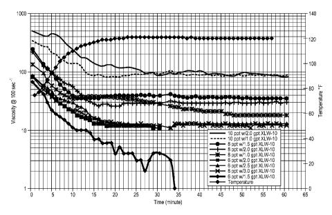
[00045] Example 4.
A fluid was formulated by adding GW-2 to water in a blender at room
temperature and then adding to the fluid a self-buffering borate crosslinker,
commercially available from BJ Services Company as XLW-10. The crosslinked
fluid formed in approximately 5 seconds. The loading of the polymer in the
fluid
was between from 6 pptg to 10 gptg. The amount of crosslinker in the fluid was
varied to be between 1.5 gptg and 3.0 gptg. About 30 ml of a 10 pptg fluid was
then placed into a Fann 50 viscometer cup having a bob (BX5) and rotor (R1)
cup
assembly. The cup was then placed on a Fann 50 viscometer. The sample was
sheared by a rate sweep of 100 sec-1 for about 1 minute. The stresses
associated to
each rate were used to calculate the power law indices n and K; n refers to
flow
behavior index and K refers to consistency index set forth in the American
Petroleum Institute's Bulletin RP-39. The fluid viscosity was then calculated
by
using the n' and k' values. FIG. 5 shows the viscosity profiles of each of the
fluids
as the temperatures was increased from ambient to 120 F. Initial viscosities
for the
example fluids at 75 F ranged from 70cP for the 6 pptg GW-2/1.5 gpt XLW-10
formulation, to 500 cP for the 10 pptg GW-2/2.0 gpt XLW-10 case. Fluid
temperatures were observed to approach the desired test temperature of 120 F
after
20 minutes, at which time the 8 pptg polymer formulations exhibited
viscosities
between 20 cP and 30 cP. Viscosities of the 6 pptg formulations after 20
minutes
were approximately 10 cP.
[00046] Example 5.
A fluid was formulated by adding 10 pptg of GW-2 to water in a blender at
room temperature and then adding 3 ppt of boric acid as a crosslinker, 2 gptg
of
10% caustic to bring the pH to about 9.5, and 0.125 ppt to 0.5 ppt of ammonium
persulfate breaker, available from BJ Services as GBW-5. The crosslinked fluid
began to form in approximately 5 seconds. About 30 ml of a 10 pptg fluid was
then
13
CA 02783471 2014-04-10
MO 2011/075629
PCT/US2010/060979
=
placed into a Fann 50 viscometer cup having a bob (BX5) and rotor (RI) cup
assembly. The cup was then placed on. a Farm 50 viscometer. The sample was
sheared by a rate sweep of 100 sec-I for about I minute. The stresses
associated to
each rate were used to calculate the power law indices n and K; n refers to
flow
behavior index and K refers to consistency index set forth in the American
Petroleum Institute's Bulletin RP-39. The fluid viscosity was then calculated
by
using then' and k' values. FIG. 6 shows the viscosity profiles of each of the
fluids
as the temperatures was increased from ambient to 150 F. Viscosities for the
example fluids were approximately 40 cP after about 30 seconds, and peaked at
greater than 60 cP between 2 minutes and 5 minutes. After approximately 10
minutes, the temperature had increased to about 120 F, and the viscosities of
each
of the fluids declined to between 10 and 15 cP. After 20 minutes, the
temperature
was at the target of I50 F and the fluids viscosities were observed to be less
than 10
cP for each of the fluid formulations including breaker.
14