Note: Descriptions are shown in the official language in which they were submitted.
CA 02783531 2012-07-24
Description
Title of the Invention
INJECTION MOLDING MACHINE
Technical Field
The present invention relates to an
injection molding machine which includes a motor, a
driver circuit that drives the motor; a rectifying
part that supplies electric power to the driver
circuit; and a bridge circuit that converts direct
electric power between the driver circuit and the
rectifying part into alternating electric power.
Background Art
Patent Document 1 discloses an electric
power control device which includes a rectifying
part which converts alternating electric power of a
power supply into direct electric power; a capacitor
connected to the output side of the rectifying part;
an inverter which converts the direct electric power
of the capacitor into the alternating electric
power; and a collective controlling part which
includes a PWM switch circuit connected to the
rectifying part in parallel, wherein the collective
controlling part has a harmonics removing function
and an electric power regenerating function. The
collective controlling part functions as an active
filter to remove the harmonics of the alternating
electric power of the power supply if the voltage of
the capacitor is lower than a predetermined value,
and functions as a power regenerating converter to
supply the electric power of the capacitor to the
power supply if the voltage of the capacitor is
higher than the predetermined value.
[Patent Document 1] Japanese Laid-open
Patent Publication No. 2005-223999
1
CA 02783531 2012-07-24
Disclosure of Invention
Problem to be Solved by Invention
However, if the PWM switch circuit is
simply connected to the rectifying part in parallel
as is the case with the prior art described above, a
return path of the current flowing through the
rectifying part is formed in the PWM switch circuit.
This current is called a circulating current, and
the circulating current causes power loss.
Therefore, an object of the invention is
to provide an injection molding machine which can
reduce the circulating current passing through the
rectifying part.
Means to Solve the Problem
In order to achieve the object, an
injection molding machine according to the present
invention includes a motor; a driver circuit that
drives the motor; a rectifying part that supplies
electric power to the driver circuit; a capacitor
provided between the driver circuit and the
rectifying part; a bridge circuit that converts
direct electric power between the driver circuit and
the rectifying part into alternating electric power;
a harmonics component reducing part connected to an
alternating side of the bridge circuit; and a
regenerative line connected to the rectifying part
in parallel, wherein the bridge circuit and the
harmonics component reducing part are provided in
the regenerative line, and plural switching elements
of the bridge circuit are switched between ON state
and OFF state such that electric power of the motor
is regenerated when a voltage of the capacitor is
greater than or equal to a predetermined value, and
all the switching elements are turned off when the
voltage of the capacitor is smaller than the
2
CA 02783531 2012-07-24
predetermined value.
Advantage of the Invention
According to the invention, the
circulating current passing through the rectifying
part can be red-aced.
Brief Description of Drawings
Fig. 1 is a diagram for illustrating a
configuration of an injection molding machine 1
according an embodiment of the present invention.
Fig. 2 is a diagram for schematically
illustrating an example of a motor driving power
supply circuit including a converter 100 of the
injection molding machine 1.
Fig. 3 is a diagram for illustrating an
example of a circuit configuration of the converter
100.
Fig. 4 is a diagram for illustrating a
first configuration example of a harmonics component
reducing part 63.
Fig. 5 is a diagram for illustrating a
second configuration example of a harmonics
component reducing part 63.
Fig. 6 is a functional block diagram of a
controller 26.
Fig. 7 is a flowchart for illustrating a
method of controlling the converter 100 according to
the present embodiment.
Description of Reference Symbols
1 injection molding machine
11 servo motor
12 ball screw
13 nut
14 pressure plate
15, 16 guide bar
3
CA 02783531 2012-07-24
17 bearing
18 load cell
19 inflection shaft
20 screw
21 heating cylinder
21-1 nozzle
22 hopper
23 coupling member
24 servo motor
25 load cell amplifier
26 controller
27 position detector
28 amplifier
31, 32 encoder
35 user interface
42 servo motor
44 servo motor
43, 45 encoder
51,52,53,54 motor driver circuit
61 current detecting part
62 voltage detecting part
63 harmonics component reducing part
64a through 64f inductor
65a through 65f capacitor
71 PMW generator
72 phase detecting circuit
81 powering line
82 regenerative line
100 converter
102 rectifier (rectifying part)
104 bridge circuit (converting part)
190 voltage detecting part
200 power supply
261 converter controlling part
263 regeneration determining part
3C0 DC link
301 capacitor
4
CA 02783531 2012-07-24
Best Mode for Carrying Out the Invention
In the following, embodiments for carrying
out the present invention will be described in
detail by referring to the accompanying drawings.
Fig. I is a diagram for illustrating a configuration
of an injection molding machine 1 according an
embodiment of the present invention.
The injection molding machine 1, which is
a motor-operated injection molding machine in the
illustrated example, includes a servo motor for
injection 11. The rotation of the servo motor for
nj ecta on 11 is transmitted to a ball screw 12. A
nut 13, which is moved in the forward and backward
directions by the rotation of the ball screw 12, is
fixed to a pressure plate 14. The pressure plate 14
is configured to be movable along guide bars 15 and
16 which are fixed to a base frame (not illustrated).
The motion of the pressure plate 14 in forward and
backward directions is transmitted to a screw 20 via
a bearing 17, a load cell 18 and an injection shaft
19. The screw 20 is disposed in a heating cylinder
21 in such a manner that it can rotate in the
heating cylinder 21 and can move in an axial
direction. A hopper 22 for supplying a resin is
provided in a rear portion in the heating cylinder
21. The rotational motion of a servo motor for
screw rotation 24 is transmitted to the injection
shaft 19 via coupling members 23 such as a belt, a
pulley, etc. In other words, the screw 20 is
rotated when the injection shaft 19 is driven to
rotate by the servo motor for screw rotation 24.
In a plasticizing/metering process, the
screw 20 is rotated and moved backward in the
heating cylinder 21, thereby molten resin is stored
in a front portion of the screw 20, that is to say,
on the side of a nozzle 21-1 of the heating cylinder
5
CA 02783531 2012-07-24
21. In an injecting process, molds (dies) are
filled with the molten resin stored in the front
portion of the screw 20, and molding is performed by
applying pressure. At that time, a force pressing
the resin is detected by the load cell 18 as a
reaction force. In other words, a resin pressure in
the front portion of the screw 20 is detected. The
signal representing the detected pressure is
amplified by a load cell amplifier 25 and input to a
controller 26 (a control apparatus) functioning as
controlling means. Further, in a holding process,
the pressure of the resin filling in the molds is
held at a predetermined pressure.
A position detector 27 for detecting an
amount of movement of the screw 20 is attached to
the pressure plate 14. The detection signal of the
position detector 27 is amplified by an amplifier 28
and input to the controller 26. This detection
signal may be used to detect a movement speed of the
screw 20.
The servo motor 11 and 24 are provided
with encoders 31 and 32 for detecting a number of
revolutions, respectively. The numbers of
revolutions detected by the encoders 31 and 32 are
input to the controller 26.
A servo motor 42 is provided for opening
and closing the molds, and a servo motor 44 is
provided for extruding (ejecting) a molded article.
The servo motor 42 drives a toggle link (not
illustrated), for example, to implement the mold
opening/closing. Further, the servo motor 44 moves
an ejector rod (not illustrated) via a ball screw
mechanism, for example, to implement the ejection of
the molded article. The servo motor 42 and 44 are
provided with encoders 43 and 45 for detecting a
number of revolutions, respectively. The numbers of
revolutions detected by the encoders 43 and 45 are
6
CA 02783531 2012-07-24
input to the controller 26.
The controller 26 is comprised mainly of a
microprocessor that includes a CPU, a ROM in which
control programs are stored, a RAM in which
calculation results are stored, a timer, a counter,
an input interface, an output interface, etc., for
example.
The controller 26 transmits current
(torque) instructions to motor driver circuits
according to the respective processes in an
injection molding process. The motor driver
circuits drive the servo motors 11, 24, 42 and 44
used in the respective processes according to the
instructions. For example, the controller 26
controls the number of revolutions of the servo
motor 24 with the motor driver circuit 52 to
implement the plasticizing/metering process.
Further, the controller 26 controls the number of
revolutions of the servo motor 11 with the motor
driver circuit 51 to implement the injecting process
and the holding process. Further, the controller 26
controls the number of revolutions of the servo
motor 42 with the motor driver circuit 53 to
implement the mold opening process and the mold
closing process. Further, the controller 26
controls the number of revolutions of the servo
motor 44 with the motor driver circuit 54 to
implement the molded article ejecting process.
A user interface 35 includes an input
setting part with which injection molding conditions
can be set for the respective processes, such as a
mold opening/closing process, an injecting process,
etc. Further, the user interface 35 includes an
input part with which a user inputs various
instructions and an output part (a display part, for
example) configured to output various items of
information.
7
CA 02783531 2012-07-24
Typically, a cycle of the injection
molding process in the injection molding machine 1
includes a mold closing process for closing the
molds; a mold clamping process for clamping the
molds; a nozzle contacting process for abutting a
nozzle 21-1 onto a sprue (not illustrated) of the
molds; an injecting process for moving the screw 20
in the heating cylinder 21 to inject the molten
resin stored in the front portion of the screw 20
into a mold cavity (not illustrated); a holding
process for maintaining the dwell pressure afterward
for a while so as to prevent emergence of air
bubbles and sink marks; a plasticizing/metering
process and a cooling process for melting the resin
and storing the molten resin in the front portion of
the heating cylinder 21 by rotating the screw 20 so
as to prepare for the next cycle, utilizing the time
until the molten resin filling in the mold cavity is
cooled to set; a mold opening process for opening
the molds; and a molded article ejecting process for
pushing the molded article out with ejector pins
(not illustrated) provided in the mold.
Fig. 2 is a diagram for schematically
illustrating an example of a motor driving power
supply circuit including a converter 100 of the
injection molding machine 1. In Fig. 2, the servo
motor for injection 11 and a motor driver circuit 51
for driving the servo motor for injection 11 are
illustrated as an example. Other servo motors 24,
42 and 44 and the motor driver circuits 52, 53 and
54 may be the same. According to an alternative
embodiment, the converter 100 may be connected to
servo motors and motor driver circuits for driving
the servo motors in parallel.
The converter 100 is connected to a power
supply 200. The power supply 200 may be an AC power
supply. Further, the converter 100 is connected to
8
CA 02783531 2012-07-24
the servo motor 11 via a DC link 300 and the motor
driver circuit 51. The converter 100 converts the
electric power from the power supply 200 to supply
the converted electric power to the servo motor 11
via the DC link 300 and the motor driver circuit 51.
The motor driver circuit 51 may be an inverter for
converting the output (direct electric power) of the
converter 100 to a three-phase alternating electric
power, for example, and the inverter may include a
three-phase bridge circuit having six power
transistors, for example. The DC link 300 includes
a capacitor (a capacitor), a bus bar, a cable, or
the like.
A voltage detecting part 190 is provided
such that it detects the voltage across the DC link
300 which is provided between the output side of a
rectifier 102 (see Fig. 3) and the input side of the
motor driver circuit 51. The direct voltage
detected by the voltage detecting part 190 is
supplied to the controller 26 as the charged voltage
of the capacitor 301 of the DC link 300 (see Figs. 3
and 6).
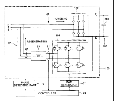
Fig. 3 is a diagram for illustrating an
example of a circuit configuration of the converter
100. In the example illustrated in Fig. 3, the
converter 100 includes terminals R, S and T which
are connected to the AC power supply and terminals P
and N which are connected to the capacitor 301 of
the DC link 300. The capacitor 301 is an
electrolytic capacitor, for example. The converter
100 includes a rectifier (powering circuit part) 102
which is formed of a three-phase diode bridge
including six diodes, and a bridge circuit
(regenerating circuit part) 104 which is formed of a
3a three-phase inverter including switching elements
such as six transistors. It is noted that in Fig. 3
the flow of the electric power at the time of the
9
CA 02783531 2012-07-24
powering mode and the flow of the electric power at
the time of the regenerating mode are indicated by
arrows.
The rectifier 102 performs a conversion
operation (powering operation) from the alternating
electric power to the direct electric power in the
DC link 300 with diode rectification. The bridge
circuit 104 performs a PWM (Pulse Width Modulation)
control according to a driving signal output from a
PWM generator 71 to implement a conversion operation
(power supply regenerating operation) from the
direct electric power in the DC link 300 to the
alternating electric power in the alternating power
supply. The bridge circuit 104 controls magnitude
of the alternating electric power (alternating
electric current) between the alternating power
supply and the bridge circuit 104 and magnitude of
the direct electric power (direct electric current)
of the DC link 300 during the power supply
regenerating operation.
As illustrated in Fig. 3, the converter
100 includes a regenerative line 82 connected to a
powering line 81 in parallel. The powering line 81
is between. the alternating power supply and the
motor driver circuit and has the rectifier 102
provided therein. To the alternating input side of
the rectifier 102 is input the alternating electric
power of the alternating power supply, and to
terminal electrodes P and N on the direct output
side of the rectifier 102 is connected the capacitor
301. The regenerative line 82 is connected to the
input and the output of the rectifier 102 in
parallel. The regenerative line 82 has the bridge
circuit 104 and a harmonics component reducing part
63 inserted in series therein. One end of the
regenerative line 82 is connected to an alternating
current line part of the powering line 81 on the
CA 02783531 2012-07-24
input side of the rectifier 102, with connecting the
harmonics component reducing part 63, the bridge
circuit 104 and the alternating input part of the
rectifier 102, and the other end of the regenerative
line 82 is connected to a direct current line part
of the powering line 81 on the direct output side of
the rectifier 102, with connecting the direct input
part of the bridge circuit 104 and the direct output
part of the rectifier 102.
The bridge circuit 104 is a converting
part which converts the direct electric power
between the output side of the rectifier 102 and the
input side of the motor driver circuit 51 (see Fig.
2) into the alternating electric power. The
harmonics component reducing part 63 is connected to
the alternating output side of the bridge circuit
104. The alternating electric power- output by the
power conversion operation of the bridge circuit 104
is input to the harmonics component reducing part 63.
For example, the harmonics component reducing part
63 may function as a reactor part which has reactors
inserted in series in the regenerative line 82 which
is connected to midpoints between the upper
switching elements and the lower switching elements
of the bridge circuit 104.
The harmonics component reducing part 63
has an LC circuit configuration in which plural
inductors inserted to the respective phases of R, S
and T in series are connected to capacitors
(capacitors), for example. The harmonics component
reducing part 63 may have a Y-connection
configuration in which plural capacitors whose ends
are connected to. the respective phases are commonly
connected at a neutral point, as illustrated in Fig.
4. The harmonics component reducing part 63 may
have a delta connection configuration in which the
capacitors are connected between the respective
11
CA 02783531 2012-07-24
phases, as illustrated in Fig. 5. Further, the
harmonics component reducing part 63 may be
configured such that only the inductors are inserted
to the respective phases in series, or may be
configured such that resistors are inserted to the
respective phases in series.
Further, the injection molding machine 1
includes, as a controlling part of the converter 100,
the controller 26, the PWM generator 71 which
generates a PWM driving signal, and a phase
detecting part 72 which detects the phase of the
alternating voltage of the alternating power supply.
If the direct voltage value Vdc detected
by the voltage detecting part 190 (see Fig. 2) is
higher than a predetermined threshold voltage Vth,
the controller 26 performs PWM control with the PMW
generator 71 such that the bridge circuit 104
functions as a power regenerating converter, thereby
regenerating the electric power of the servo motor
11, which is input to the bridge circuit 104 via the
motor driver circuit 51, to the power supply. The
controller 26 controls the regenerating operation of
the bridge circuit 104 with the P"WM driving signal
generated by the PMW generator 71 such that the
alternating current output from the bridge circuit
104 is shaped to have a shape of a sine wave.
For example, the controller 26 controls
the regenerating operation by the switching
operation of the bridge circuit 104 with the PMW
generator 71, based on the direct voltage value Vdc
detected by the voltage detecting part 190 (see Fig.
2), the alternating current value Iacf detected by a
current detecting part 61, and an alternating
voltage value Vacf detected by a voltage detecting
part 62, such that the alternating current output
from the bridge circuit 104 has a sine wave shape
with a target frequency. A phase detecting part 72
12
CA 02783531 2012-07-24
is capable of detecting the phase of the alternating
voltage of the alternating power supply based on the
alternating voltage value Vacf detected by the
voltage detecting part 62.
For example, the controller 26 generates a
sine-wave instruction value Ir of the alternating
current by performing processes, such as a process
of multiplying a voltage error output Verr, which is
generated according to an error between an
instruction value Vr of the direct voltage and the
direct voltage value Vdc supplied from the voltage
detecting part 190, by the alternating voltage value
Vacf supplied from the phase detecting part 72.
Then, the controller 26 supplies an current error
output Ierr, which is generated according to an
error between the sine-wave instruction value Ir and
the alternating current value Iacf supplied from the
current detecting part 61, to the PMW generator 71.
The PMW generator 71 compares the current error
output Ierr with a predetermined carrier such as a
triangle wave to generate the PWM driving signal for
driving the gates of the transistors of the bridge
circuit 104 to implement the regenerating operation.
Further, if the direct voltage value Vdc
detected by the voltage detecting part 190 (see Fig.
2) is lower than the predetermined threshold voltage
Vth, the controller 26 turns off all the switching
elements of the bridge circuit 104 with the PMW
generator 71 to reduce a circulating current, which
is the total of currents flowing through the
respective phases R, S and T of the regenerative
line 02, thereby reducing such a circulating current
flowing through the rectifier 102.
When all the switching elements of the
bridge circuit 104 are turned off, the harmonics
component reducing part 63 has three terminal
potentials on the side of the bridge circuit 104
13
CA 02783531 2012-07-24
changed to potential of a terminal electrode P or N
(neglecting forward voltage of the diodes connected
to the switching elements in parallel) such that the
currents flowing through the respective phases are
reduced.
Specifically, if the switching elements of
the bridge circuit 104 are turned off when the
current flows through the harmonics component
reducing part 63 from the alternating power supply
to the bridge circuit 104, the terminal potential of
the harmonics component reducing part 63 on the side
of the bridge circuit 104 is changed to the
potential of the terminal electrode P by the diodes
connected in parallel to the switching elements or
the high side. If the terminal potential of the
harmonics component reducing part 63 on the side of
the bridge circuit 104 is changed to the potential
of the terminal electrode P, the three-phase
currents flowing through the harmonics component
reducing part 63 are reduced. Conversely, if the
switching elements of the bridge circuit 104 are
turned off when the current flows through the
harmonics component reducing part 63 from the bridge
circuit 104 to the alternating power supply, the
terminal potential of the harmonics component
reducing part 63 on the side of the bridge circuit
104 is changed to the potential of the terminal
electrode N by the diodes connected in parallel to
the switching elements on the low side. If the
terminal potential of the harmonics component
reducing part 63 on the side of the bridge circuit
104 is changed to the potential of the terminal
electrode N, the three-phase currents flowing
through the harmonics component reducing part 63 are
reduced.
In this way, by turning off all the
switching elements of the bridge circuit 104, three-
14
CA 02783531 2012-07-24
phase currents flowing through the harmonics
component reducing part 63 are reduced and thus the
circulating current, which is the total of three-
phase currents, is reduced.
if the harmonics component reducing part
63 has reactors inserted in series in the current
lines of the respective phases, turning off all the
switching elements of the bridge circuit 104 reduces
the three-phase currents flowing through the
reactors and thus reduces the circulating current
which is the total of three-phase currents. In
other words, since energy, which is accumulated in
the reactors by the currents flowing through the
reactors before all the switching elements of the
bridge circuit 104 are turned off, is charged to the
capacitor 301, the generation of the circulating
current can be reduced.
Fig. 6 is a functional block diagram of
the controller 26 which functions as a control
apparatus of the converter 100. It is noted that
the control apparatus of the converter 100 may be
implemented by a control apparatus other than the
controller 26.
The controller 26 includes a converter
controlling part 261 and a regeneration determining
part 263. The controller 26 includes one or more
calculation processing apparatuses and a storage
device for storing software (programs) and data,
etc., such as a RAM and a ROM. The respective
functional parts 261 and 263 of the controller 26
are functional parts for performing various
processes for input data, using the calculation
processing apparatus mainly, and are implemented by
a hardware resource, a software resource or a
combination thereof. The functions of the
respective functional parts 261 and 263 are
described with reference to Fig. 7.
CA 02783531 2012-07-24
Fig. 7 is a flowchart for illustrating an
example of a method of controlling the converter 100
according to the present embodiment. The control
process illustrated in Fig. 7 is executed by the
controller 26 in connection with the regeneration of
the servo motor 11 (at the time of decelerating the
injection speed in the case of the servo motor 11).
In step 10, the converter controlling part
261 performs the regenerating operation by
controlling the switching operation of the
transistors of the bridge circuit 104 with the PMW
generator 71 such that the alternating current
output from the bridge circuit 104 has a shape of a
sine wave.
In step 12, the regeneration determining
part 263 acquires the voltage Vdc across the
capacitor 301 of the DC link 300 with the voltage
detecting part 190 to determine the regenerating
status of the motor during the regenerating
operation.
In step 14, the regeneration determining
part 263 determines whether the voltage Vdc of the
capacitor 301 of the DC link 300 is smaller than a
predetermined threshold voltage Vth. The
regeneration determining part 263 determines that
the motor is in the decelerating status and a
recoverable regenerative electric power is generated
in the motor if the voltage Vdc is greater than or
equal to the predetermined threshold voltage Vth.
The converter controlling part 261 continues the
regenerating operation of the bridge circuit 104 if
it is determined by the regeneration determining
part 263 that the voltage Vdc is greater than or
equal to the predetermined threshold voltage Vth
(i.e., it is determined that the recoverable
regenerative electric power is generated in the
motor). On the other hand, the regeneration
16
CA 02783531 2012-07-24
determining part 263 determines that a regeneration
stop criterion of the motor is met, if the voltage
Vdc is smaller than the predetermined threshold
voltage Vth.
In step 16, the converter controlling part
261 stops the regenerating operation of the bridge
circuit 104 with the PMW generator 71 by tuning off
all the transistors of bridge circuit 104, if it is
determined by the regeneration determining part 263
that a regeneration stop criterion is met (i.e., if
the voltage Vdc is smaller than the predetermined
threshold voltage Vth). With this arrangement, the
circulating current flowing through the rectifying
part can be reduced. The regeneration determining
part 263 may determine that the regeneration stop
criterion is met, if the direct voltage value Vdc
detected by the voltage detecting part 190 is
smaller than the threshold voltage Vth.
In step 18 in order to determine the
regenerating status of the motor, the regeneration
determining part 263 acquires the voltage Vdc across
the capacitor 301 of the DC link 300 with the
voltage detecting part 190 and determines whether
the voltage Vdc of the capacitor 301 of the DC link
300 is greater than the threshold voltage Vth. The
regeneration determining part 263 determines that
the recoverable regenerative electric power is not
generated yet in the motor if the voltage Vdc is not
greater than the threshold voltage Vth.
The converter controlling part 261
continues to turn off all the transistors of the
bridge circuit 104 if it is determined by the
regeneration determining part 263 that the voltage
Vdc is not greater than the threshold voltage Vth
(i.e., it is determined that the recoverable
regenerative electric power is not generated in the
motor).
17
CA 02783531 2012-07-24
On the other hand, the converter
controlling part 261 restarts the regenerating
operation by controlling the switching operation of
the transistors of the bridge circuit 104 with the
PMW generator 71 such that the alternating current
output from the bridge circuit 104 has a shape of a
sine wave, if it is determined by the regeneration
determining part 263 that the voltage Vdc is greater
than the threshold voltage Vth (i.e., it is
determined that the recoverable regenerative
electric power is generated in the motor).
In this way, according to the embodiment,
by turning off all the transistors of the bridge
circuit 104, the current flowing through the
reactors of the harmonics component reducing part 63
is reduced and thus useless circulating current does
not flow through the rectifier 102, thereby reducing
power loss.
Further, since the bridge circuit 104 and
the harmonics component reducing part 63 have only
the regenerative current flowing therethrough (i.e.,
the powering current does not flow through the
bridge circuit 104 and the harmonics component
reducing part 63), the rating of the bridge circuit
104 and the harmonics component reducing part 63 can
be decreased in comparison with a case where a
powering line and a regenerative line is common.
For example, it is possible to select the switching
elements such as the transistors, the inductors,
etc., according not to the powering electric power
,but the regenerative electric power. Further, the
regeneration by the PWM control using the PMW
generator 71 increases the power factor.
The present invention is disclosed with
reference to the preferred embodiments. However, it
should be understood that the present invention is
not limited to the above-described embodiments, and
18
CA 02783531 2012-07-24
variations and modifications may be made without
departing from the scope of the present invention.
For example, according to the present
embodiment, a voltage or a current as a dimension of
a physical quantity is used for control; however,
substantially the same control can be performed by
equivalently using other dimensions of a physical
quantity such as energy.
Further, in Fig. 7, the threshold voltage
Vth in step 14 and the threshold voltage Vth in step
l8 may be the same or may differ from each other,
for example.
19