Language selection

Search

Patent 2783834 Summary

Third-party information liability

Some of the information on this Web page has been provided by external sources. The Government of Canada is not responsible for the accuracy, reliability or currency of the information supplied by external sources. Users wishing to rely upon this information should consult directly with the source of the information. Content provided by external sources is not subject to official languages, privacy and accessibility requirements.

Claims and Abstract availability

Any discrepancies in the text and image of the Claims and Abstract are due to differing posting times. Text of the Claims and Abstract are posted:

  • At the time the application is open to public inspection;
  • At the time of issue of the patent (grant).
(12) Patent: (11) CA 2783834
(54) English Title: EAVESTROUGH COVER
(54) French Title: COUVERCLE POUR GOUTTIERE
Status: Granted
Bibliographic Data
(51) International Patent Classification (IPC):
  • E04D 13/076 (2006.01)
(72) Inventors :
  • BROCHU, STEPHANE (Canada)
(73) Owners :
  • BROCHU, STEPHANE (Canada)
(71) Applicants :
  • BROCHU, STEPHANE (Canada)
(74) Agent: ROBIC AGENCE PI S.E.C./ROBIC IP AGENCY LP
(74) Associate agent:
(45) Issued: 2015-10-06
(22) Filed Date: 2012-07-26
(41) Open to Public Inspection: 2013-08-27
Examination requested: 2013-06-20
Availability of licence: N/A
(25) Language of filing: English

Patent Cooperation Treaty (PCT): No

(30) Application Priority Data: None

Abstracts

English Abstract

An eavestrough cover comprising a first side structure and a second side structure with a central planar portion intermediate the side structures, the central portion having a plurality of longitudinally extending sections with each being separated from each other by a rollback member, the rollback members extending longitudinally and having one face thereof of a C-shaped configuration, all of the rollbacks facing in the same direction, each of the longitudinally extending sections having a plurality of apertures formed therein. The rollback structure helps prevent overflow of the eavestrough.


French Abstract

Un recouvrement de gouttière comporte une première structure latérale et une deuxième structure latérale comportant une portion plane centrale entre les structures latérales, la portion centrale comportant une pluralité de sections se prolongeant longitudinalement où chacune est séparée de l'autre par un élément enrouleur, les éléments enrouleur se prolongeant longitudinalement et comportant une surface en forme de C, tous les éléments enrouleurs faisant face à la même direction, chacune des sections se prolongeant longitudinalement comportant une pluralité d'ouvertures formées intégralement. La structure d'enrouleur aide à prévenir le débordement de la gouttière.

Claims

Note: Claims are shown in the official language in which they were submitted.


The embodiments of an invention in which an exclusive property or privilege is

claimed is defined as follows:

1. A cover for an eavestrough comprising a first side structure and a
second side
structure, a central planar portion intermediate said first side structure and
said second
side structure; said central portion having a plurality of longitudinally
extending sections,
each of said longitudinally extending sections being separated from each other
by a
rollback member, each of said rollback members extending longitudinally and
having one
face thereof of a C-shaped configuration, each of said faces having a C-shaped

configuration facing the same direction towards said second side structure;
and each of
said longitudinally extending sections having a plurality of apertures formed
therein.
2. The cover of claim 1 wherein said first side structure joins one of said
rollback
members.
3. The cover of claim 2 wherein said first side structure further includes
a flange for
securement to an eavestrough, a downwardly extending channel being defined
between
said flange and said one rollback member, said channel having apertures formed
therein.
4. The cover of claim 1 wherein said second side structure includes a
flexible sealing
strip, said sealing strip being retained by said second side structure.
5. The cover of claim 1 wherein each of said faces of said rollback members
having a
C-shaped configuration has apertures formed therein.
6. The cover of claim 1 wherein there are provided between two and six
rollbacks.
7. The cover of claim 4 wherein said sealing strip is retained by said
second side
structure to extend diagonally upwardly.

-6-


8. In combination, an eavestrough having a rear wall, a bottom wall, a
front wall, and
an inwardly extending top wall section joining said front wall, and a cover
for said
eavestrough, said cover comprising a first side structure and a second side
structure, a
central planar portion intermediate said first side structure and said second
side structure;
said central portion having a plurality of longitudinally extending sections,
each of said
longitudinally extending sections being separated from each other by a
rollback member,
each of said rollback members extending longitudinally and having one face
thereof of a
C-shaped configuration, each of said faces having a C-shaped configuration
facing the
same direction towards said second side structure; and each of said
longitudinally extending
sections having a plurality of apertures formed therein.
9. The combination of claim 8 wherein said first side structure joins one
of said rollback
members.
10. The combination of claim 9 wherein said first side structure further
includes a flange
for securement to an eavestrough, a downwardly extending channel being defined
between
said flange and said one rollback member, said channel having apertures formed
therein.
11. The combination of claim 8 wherein said second side structure includes
a flexible
sealing strip, said sealing strip being retained by said second side
structure.
12. The combination of claim 8 wherein each of said faces of said rollback-
members
having a C-shaped configuration has apertures formed therein.
13. The combination of claim 8 wherein there are provided between two and
six rollbacks.
14. The combination of claim 11 wherein said sealing strip is retained by
said second side
structure to extend diagonally upwardly.

-7-

Description

Note: Descriptions are shown in the official language in which they were submitted.


CA 02783834 2012-07-26
EAVESTROUGH COVER
FIELD OF THE INVENTION
The present invention relates to a cover for an eavestrough.
BACKGROUND OF THE INVENTION
The use of covers for gutters or eavestroughs is well known in the art and
there have
been many proposals for different types of covers. The purpose of the cover is
essentially to
permit the passage of rainwater from the roof to the eavestrough while
protecting the same
from extraneous foreign matters such as leaves, twigs and the like.
There have been several different approaches which have been proposed in the
prior
art with respect to the design of covers. A first approach which is widely
used is a cover
which is foraminous and permits passage of rainwater while attempting to bar
the passage of
extraneous matter. There are many different designs with some of these not
functioning as
well as might be desired. In order to overcome problems, it has also been
proposed that the
eavestrough itself be mounted for pivotal movement such that it may be emptied
at desired
intervals.
A still further approach which has been taken is utilizing a design wherein a
cover
has an outer edge which fills downwardly and the water follows a curved
portion due to
surface tension and thereafter cascades into the eavestrough. While this
structure works
under certain conditions, when the volume of water becomes sufficiently large,
the surface
tension is insufficient to direct all the water into the eavestrough.
SUMMARY OF THE INVENTION
It is an object of the present invention to provide a cover for an eavestrough
which
can handle relatively high flows of water while preventing the entry of
extraneous material.
- 1 -

CA 02783834 2012-07-26
According to one aspect of the present invention, there is provided a cover
for an
eavestrough comprising a first side structure and a second side structure, a
central planar
portion intermediate the first side structure and the second side structure,
the central portion
having a plurality of longitudinally extending sections, each of the
longitudinally extending
sections being separated from each other by a rollback member, each of the
rollback
members extending longitudinally and having one face thereof of a C-shaped
configuration,
each of the faces having a C-shaped configuration facing the same direction
towards the
second side structure, and each of the longitudinally extending sections
having a plurality of
apertures formed therein.
According to a further aspect of the present invention, there is also provided
in
combination, an eavestrough having a rear wall, a bottom wall, a front wall,
and an inwardly
extending top wall section joining the front wall, and a cover for the
eavestrough, the cover
comprising a first side structure and a second side structure, a central
planar portion
intermediate the first side structure and the second side structure, the
central portion having
a plurality of longitudinally extending sections, each of the longitudinally
extending sections
being separated from each other by a rollback member, each of the rollback
members
extending longitudinally and having one face thereof of a C-shaped
configuration, each of
the faces having a C-shaped configuration facing the same direction towards
the second side
structure, and each of the longitudinally extending sections having a
plurality of apertures
formed therein.
The cover of the present invention utilizes a plurality of "rollbacks" which
are
structures designed to redirect the flow of water to prevent overflow of the
eavestrough.
These rollbacks extend longitudinally of the cover and prevent a rush of water
from running
_ 2 _

CA 02783834 2012-07-26
to the side and then overflowing.
The device of the present invention may be formed of any suitable material and
is
conveniently formed either of metallic or plastic material. As is known in the
art, metallic
materials such as aluminum may conveniently be used. However, it is within the
scope of
the present invention for one to use other materials and they may either be
similar or
dissimilar.
The device of the present invention prevents foreign matter from entering into
the
eavestrough. In order to do so, there are provided a plurality of apertures to
permit the
passage of rainwater through the cover while still preventing extraneous
matter from
entering the eavestrough. Sizing of the apertures is well known in the art and
generally they
will have a size of between 2.5 and 10 mm.
The first side structure may be adjacent the front wall of an eavestrough and
may be
secured to a top wall of a K type eavestrough. The cover is also provided with
a channel
adjacent to the front wall of the eavestrough. The channel is defined by a
pair of walls and
at the bottom of which, there is provided an opening to aid in drainage of the
water. The
second side structure will preferably include a sealing strip which is
retained by the second
side structure. The sealing strip is preferably of a flexible material and is
designed to abut
the eaves to prevent water from going between the second side structure and
the cave.
The number of rollbacks formed in the cover may vary. Any number between two
and six are preferred. Each rollback preferably extends a height above the
planar portions of
between 1 mm and 6 mm.
BRIEF DESCRIPTION OF THE DRAWINGS
Having thus generally described the invention, reference will be made to the
- 3 -

CA 02242915 2015-01-12
PPH
accompanying drawings illustrating an embodiment thereof, in which:
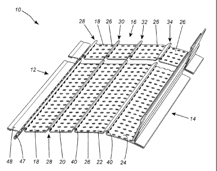
Figure 1 is a perspective view of a cover for an eavestrough according to one
embodiment of the present invention;
Figure 2 is an end elevational view thereof; and
Figure 3 is a sectional view illustrating placement of the cover on an
eavestrough.
DETAILED DESCRIPTION OF THE INVENTION
Referring to the drawings in greater detail and by reference characters
thereto, there
is illustrated in Figure 1 a cover generally designated by reference numeral
10 which can be
utilized with a conventional K type eavestrough. Naturally, it can also be
utilized with
other types of eavestrough with or without modifications.
Cover 10 includes a first side structure generally designated by reference
numeral 12
and a second side structure generally designated by reference numeral 14.
Intermediate first
side structure 12 and second side structure 14 is a central portion generally
designated by
reference numeral 16.
Central portion 16 includes a plurality of longitudinally extending sections
18, 20, 22
and 24. Each of sections 18, 20, 22 and 24 has apertures 26 therein to permit
the passage of
water therethrough. Separating the longitudinally extending sections 18, 20,
22 and 24 are
rollbacks 28, 30, 32 and 34. Each rollback has a substantially identical
configuration and
thus only one will be described herein. Rollback 28 has a wall 36 having a C-
shaped or
concave configuration. Rollback 28 also includes a second back wall 38. It
will be noted
that there are provided apertures 40 in wall 36.
Adjacent first side structure 12 is a trough 42 defined by first trough wall
44 and a
second trough wall 46. Again, it will be seen that apertures 47 are provided
at the bottom of
-4-

CA 02242915 2015-01-12
PPH
trough 42. A flange 48 extends outwardly from second trough wall 46. Flange 48
includes
a doubled under segment 50. Flange 48 is designed to be secured to the
eavestrough by
suitable mechanical fasteners.
Second side structure 14 includes a doubled back segment 52 which then merges
with
an upwardly extending wall 54 and a downwardly extending wall 56. The
structure
terminates with an upwardly extending wall 58. A sealing strip 60 is retained
between
downwardly extending wall 56 and upwardly extending wall 58.
The provision of rollbacks 28, 30, 32, and 34 assist in preventing the
overflow of
excess water over the edge and which would tend to stain the front wall of the
eavestrough.
As may be seen in Figure 3, cover 10 is installed on an eavestrough having a
rear
wall 80, a bottom wall 82, a front wall 84 and a top wall segment 86. Flange
48 is secured
to top wall segment 86 by means of mechanical fasteners (screws) 88. The
eavestrough may
be supported by a hanger shown in dash dot lines. A screw 90 may extend
through wall 58
and the hanger into an adjoining eave.
-5-

Representative Drawing
A single figure which represents the drawing illustrating the invention.
Administrative Status

For a clearer understanding of the status of the application/patent presented on this page, the site Disclaimer , as well as the definitions for Patent , Administrative Status , Maintenance Fee  and Payment History  should be consulted.

Administrative Status

Title Date
Forecasted Issue Date 2015-10-06
(22) Filed 2012-07-26
Examination Requested 2013-06-20
(41) Open to Public Inspection 2013-08-27
(45) Issued 2015-10-06

Abandonment History

There is no abandonment history.

Maintenance Fee

Last Payment of $125.00 was received on 2024-04-11


 Upcoming maintenance fee amounts

Description Date Amount
Next Payment if standard fee 2025-07-28 $347.00
Next Payment if small entity fee 2025-07-28 $125.00

Note : If the full payment has not been received on or before the date indicated, a further fee may be required which may be one of the following

  • the reinstatement fee;
  • the late payment fee; or
  • additional fee to reverse deemed expiry.

Patent fees are adjusted on the 1st of January every year. The amounts above are the current amounts if received by December 31 of the current year.
Please refer to the CIPO Patent Fees web page to see all current fee amounts.

Payment History

Fee Type Anniversary Year Due Date Amount Paid Paid Date
Application Fee $200.00 2012-07-26
Request for Examination $400.00 2013-06-20
Maintenance Fee - Application - New Act 2 2014-07-28 $50.00 2014-07-07
Final Fee $150.00 2015-06-16
Maintenance Fee - Application - New Act 3 2015-07-27 $50.00 2015-07-02
Maintenance Fee - Patent - New Act 4 2016-07-26 $50.00 2016-06-29
Maintenance Fee - Patent - New Act 5 2017-07-26 $100.00 2017-07-04
Maintenance Fee - Patent - New Act 6 2018-07-26 $100.00 2018-07-16
Maintenance Fee - Patent - New Act 7 2019-07-26 $100.00 2019-06-26
Maintenance Fee - Patent - New Act 8 2020-07-27 $100.00 2020-06-22
Maintenance Fee - Patent - New Act 9 2021-07-26 $100.00 2021-06-08
Maintenance Fee - Patent - New Act 10 2022-07-26 $125.00 2022-07-22
Maintenance Fee - Patent - New Act 11 2023-07-26 $125.00 2023-07-11
Maintenance Fee - Patent - New Act 12 2024-07-26 $125.00 2024-04-11
Owners on Record

Note: Records showing the ownership history in alphabetical order.

Current Owners on Record
BROCHU, STEPHANE
Past Owners on Record
None
Past Owners that do not appear in the "Owners on Record" listing will appear in other documentation within the application.
Documents

To view selected files, please enter reCAPTCHA code :


To view images, click a link in the Document Description column. To download the documents, select one or more checkboxes in the first column and then click the "Download Selected in PDF format (Zip Archive)" or the "Download Selected as Single PDF" button.

List of published and non-published patent-specific documents on the CPD .

If you have any difficulty accessing content, you can call the Client Service Centre at 1-866-997-1936 or send them an e-mail at CIPO Client Service Centre.


Document
Description 
Date
(yyyy-mm-dd) 
Number of pages   Size of Image (KB) 
Office Letter 2021-05-26 2 199
Office Letter 2022-09-15 1 198
Office Letter 2023-03-03 2 182
Abstract 2012-07-26 1 16
Description 2012-07-26 5 210
Claims 2012-07-26 2 85
Drawings 2012-07-26 2 45
Representative Drawing 2013-07-31 1 24
Claims 2013-06-20 2 85
Cover Page 2013-09-03 2 56
Description 2015-01-12 5 204
Claims 2015-01-12 2 86
Representative Drawing 2015-09-10 1 27
Cover Page 2015-09-10 1 51
Prosecution-Amendment 2013-06-20 7 267
Correspondence 2013-06-20 2 45
Assignment 2012-07-26 2 70
Correspondence 2013-07-02 1 10
Prosecution-Amendment 2013-08-26 1 23
Prosecution-Amendment 2014-12-04 3 214
Prosecution-Amendment 2015-01-12 7 954
Final Fee 2015-06-16 1 33