Note: Descriptions are shown in the official language in which they were submitted.
CA 02783918 2012-07-25
GROUNDING FITTING
FIELD OF THE INVENTION
This invention relates to electrical connectors and more particularly to
grounding fittings
for bonding and securing ground electrodes/ground rods to electrical
enclosures, such
as an electrical service boxes, meter boxes, and the like.
BACKGROUND OF THE INVENTION
In the field of wiring homes and buildings, whether for new construction or
for
improvements or expansion, substantial development and product improvements
have
been made. Typically, these improvements are directed to enabling installers
to
securely and safely mount any desired wiring to any desired location in the
most
efficient and quickest manner.
In any particular installation or location, various conduits or cables must be
interconnected to each other as well as connected to a primary utility power
supply in a
suitable power distributing outlet box, junction box, meter box, or other
electrical
enclosure. In these instances, flexible metal conduit and/or armor or
metalclad cables
within which the electrical power carrying wires are contained, must be
securely
mounted to the housing of a junction box or outlet box, or connected to an
appropriate
solid or rigid metal tubing or conduit so as to provide appropriate grounding.
In addition, in order to assure that the installed conduits or cables and the
electrical
power carrying wires contained therein are properly and safely installed for
operation,
power distributing outlet boxes, junction boxes, meter boxes, and other
similar
enclosures typically incorporate a ground bus bar or the like which
electrically bonds
and secures a particular box to a properly installed ground electrode or
ground rod
which is typically electrically secured to earth ground. In this way, all of
the power
1
CA 02783918 2014-04-01
carrying wires installed in the particular home or building are properly
associated with a
ground conductor that is bonded and connected to an earth ground.
Various prior art grounding fittings (also called bonding and grounding
clamps/connectors) have been developed to assist in providing a secure
electrical
ground to an electrical enclosure which are designed to interfit with a ground
electrode
or ground rod (see, for example, current assignee's US patent 7,901,256 and
7,927,157). There has also been a need to provide such a grounding fitting
which can
easily further accommodate a rigid conduit or electrical metallic tubing (EMT)
conduit
that surrounds the ground electrode or ground rod. Although prior art
grounding fittings
have provided some attachment with respect to a rigid conduit or EMT conduit,
such as
shown in Figures 5-7 of US patent 7,927,157, there has not been provided a
grounding
fitting which can be used with both a rigid conduit or EMT conduit in a way
that securely
fastens such a conduit to the grounding fitting in an inexpensive and reliable
fashion.
There has further been a need to provide for a mechanical seal between the
grounding
fitting and an electrical enclosure so as to provide a fluid resistant barrier
between the
outside and the inside of an electrical enclosure once the grounding fitting
has been
installed. It is to provide such an improved grounding fitting to which the
present
invention is directed.
SUMMARY OF THE INVENTION
Accordingly, it is an object of the present invention to provide a grounding
fitting for
mounted engagement with an electrical enclosure, comprising an elongated body
comprising a first section generally cylindrically shaped terminating at a
first end of the
elongated body and a hub section terminating at a second end of the elongated
body,
the first section having a first longitudinally extending passageway formed
therein
extending completely through the first section from the first end to an end of
the first
section opposite the first end, the passageway dimensioned for receiving a
ground
electrode/ground rod; an enlarged flange radially extending outwardly from the
first
2
CA 02783918 2014-04-01
=
section at the end opposite the first end, the flange dimensioned for abutting
contact
with a surface of the electrical enclosure surrounding a knockout hole formed
in one of a
plurality of sides the electrical enclosure, the flange further having a
circular recess
formed in a face thereof directed toward the first end of the first section,
the recess
dimensioned for receipt of an 0-ring; a first threaded aperture formed in the
first section
extending from an outer surface thereof and terminating with the
longitudinally
extending passageway, the first threaded aperture dimensioned for receipt of a
first
screw to securely fasten to the ground electrode/ground rod within the first
passageway;
the hub section of the body having a second longitudinally extending
passageway
formed therethrough, terminating with the first longitudinally extending
passageway so
as to form a continuous path through the body for receipt of the ground
electrode/ground rod, the second passageway dimensioned for receipt of a rigid
conduit/electrical metallic tubing (EMT) conduit, the hub section having a
second
threaded aperture extending from an outer surface thereof and terminating with
the
second passageway, the second threaded aperture dimensioned for receipt of a
second
screw to securely fasten to the rigid conduit/EMT conduit, wherein the outer
surface of
the first section has an outer diameter dimensioned for passage through the
knockout
hole formed in the electrical enclosure, at least a portion of the outer
surface having a
threaded zone in proximity to the flange for receipt of a locking ring so as
to enable the
grounding fitting to be securely affixed to the electrical enclosure through
the knockout
hole via contact of the flange and 0-ring with the surface of the electrical
enclosure
surrounding the knockout hole, so that the first screw mounted in the first
threaded
aperture of the first section is positioned inside the electrical enclosure
and so that a
fluid resistant seal is formed between the grounding fitting and the
electrical enclosure.
Another embodiment of the present invention is a grounding fitting as
described above,
wherein the second passageway formed in the hub section of the body
incorporates a
threaded region dimensioned for threaded engagement with threads formed on an
end
of a rigid conduit.
3
CA 02783918 2014-04-01
,
A further embodiment of the present invention is a grounding fitting as
described above,
wherein the grounding fitting is further defined as being constructed from an
electrically
conductive material.
A still further embodiment of the present invention is a grounding fitting as
described
above, wherein the electrically conductive material of the grounding fitting
is further
defined as comprising one selected from the group consisting of aluminum,
copper,
steel, zinc plated steel, and alloys thereof.
Another embodiment of the present invention is a grounding fitting as
described above,
wherein the screw associated with securely fastening to the rigid conduit/EMT
conduit is
dimensioned for receipt of an inspection tag affixed to the hub section by the
screw.
A further embodiment of the present invention is a grounding fitting as
described above,
wherein the hub section comprises a plurality of flat faces.
4
CA 02783918 2012-07-25
BRIEF DESCRIPTION OF THE DRAWINGS
For a fuller understanding of the nature and objects of the invention,
reference is made
to the following detailed description taken in conjunction with the
accompanying
drawings in which:
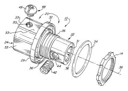
Figure 1 is a perspective view of an embodiment of the grounding fitting
according to
the present invention.
Figure 2 is a side view of the grounding fitting shown in Figure 1 installed
in an electrical
enclosure with the electrical enclosure, ground electrode and rigid or EMT
conduit
shown in phantom.
Figure 3 is an enlarged partial cross-sectional view of the grounding fitting
shown in
Figure 1 installed in an electrical enclosure in an orientation similar to
that of Figure 2.
Figure 4 is a cross-sectional view of a portion of the grounding fitting
installed in an
electrical enclosure taken along line 4-4 of Figure 3.
Figure 5 is a second perspective view of the grounding fitting shown in Figure
1,
illustrating the threads within the hub section of the body of the grounding
fitting.
Figure 6 is a cross-sectional view of the grounding fitting taken along line 6-
6 of Figure
5.
Figure 7 is a perspective view of another embodiment of the grounding fitting
according
to the present invention, showing use of two screws for securing a ground
electrode/ground rod to a first section of the body of the grounding fitting.
CA 02783918 2012-07-25
DETAILED DESCRIPTION
Figures 1-6 illustrate a first embodiment of a grounding fitting 10 according
to the
present invention. The grounding fitting comprises an elongated body 20 that
in turn
includes a first section 22 and a hub section 24. First section 22 has a first
end 31
forming an end face and an opposite en 29. Hub section 24 has a second end 33
forming an end face and an opposite end 35 adjacent opposite end 29 of first
section
22.
As seen in Figures 2, 3, and 4, the grounding fitting 10 is designed to be
installed within
an electrical enclosure 12, with the first section 22 mounted inside the
electrical
enclosure and secured thereto by means of locking ring 14. The locking ring
secures
the grounding fitting to electrical enclosure 12 by engaging with threads 26
forming a
threaded zone on the outer surface of first section 22. As best seen in
Figures 3 and 4,
the locking ring engages with a portion 28 of the electrical enclosure that
surrounds a
knockout hole 30 in the electrical enclosure, thereby forcing this portion of
the electrical
enclosure between locking ring 14 and flange 32 formed at end 29 opposite a
first end
31 of the first section 22.
An 0-ring 34 is also positioned within a circular recess 36 of the flange as
seen in
Figure 1. This 0-ring forms a fluid resistant seal about the knockout hole
thereby
keeping water and other contaminants from entering the inside of electrical
enclosure
12.
As seen in Figures 1-4, the first section 22 of grounding fitting 10 includes
a first
longitudinally extending passageway 36 positioned about axis 38 having an
inside
diameter sufficient for receipt of a ground electrode or ground rod 16. This
ground rod
is typically secured to the electrical enclosure by means of a coupler 18 and
associated
screw 19 which in turn makes electrical contact and bonding with a bus bar 40
within
the electrical enclosure.
6
CA 02783918 2012-07-25
As seen in Figures 1-4, a screw 42, such as a hex screw, is threaded within a
threaded
aperture 44 in the first fitting 22, thereby squeezing the ground
electrode/ground rod 16
to the inside wall of the passageway 36 of the first section 22, as best seen
in Figures 3
and 4. Once installed, the first section of the grounding fitting is primarily
positioned
inside the electrical enclosure, except for flange 32 and 0-ring 34.
Figures 1-6 also show the configuration of hub section 20, including the use
of the hub
section to secure a rigid conduit or electrical metallic tubing (EMT) conduit
46 to the hub
section 24 by means of screw 48. The screw 48 has a head 49 that is
sufficiently large
so as to retain an inspection tag 51, if such a tag is to be attached to
grounding fitting
10. As seen in Figure 1, the screw 24 is threaded within a threaded aperture
50 formed
within the hub so as to press against the rigid conduit or EMT conduit 46. It
should be
noted that rigid conduit typically has a threaded end region 52 as seen in
Figure 3. The
second longitudinally extending passageway 56 of the hub section can include a
threaded region 54 dimensioned for threaded engagement with the threaded end
region
52 of rigid conduit 46.
The hub section may also have a multi-faceted outer surface with a plurality
of flat faces
53 to facilitate securing the grounding fitting with a wrench or the like
during installation
of the grounding fitting to electrical enclosure 12.
The EMT conduit 46 typically does not have an outer threaded region at its
end, but is
at least secured to the hub section 24 by means of screw 48 passing within
threaded
aperture 50.
The grounding fitting 10 is typically manufactured from an electrically
conductive metal,
such as copper, aluminum, steel and alloys thereof. It can also be
manufactured from
galvanized steel (zinc plated steel).
7
CA 02783918 2012-07-25
,
As seen in Figures 2-4, once grounding fitting is installed, the ground
electrode/ground
rod 16 provides an earth ground to electrical enclosure 12 while rigid or EMT
conduit 46
provides weather and vandal protection to ground electrode/ground rod 16.
Figure 7 shows another embodiment of the present invention illustrating a
grounding
fitting 10' corresponding to that shown in Figures 1-6 except that it includes
two
threaded apertures 44 in an elongated first section 22' of elongated body 20'.
Two
screws 42 are secured in these threaded apertures so as to mechanically and
electrically secure a ground rod/ground electrode 16 passing through first
longitudinally
extending passageway 36' formed within first section 22' along axis 38 to the
passageway 36' and thus to grounding fitting 10'. The remaining components of
this
embodiment of the grounding fitting correspond to those shown in Figures 1-6.
While there have been shown and described and pointed out fundamental novel
features of the invention as applied to preferred embodiments thereof, it will
be
understood that various omissions and substitutions and changes in the form
and
details of the devices and methods described may be made by those skilled in
the art
without departing from the spirit of the invention. For example, it is
expressly intended
that all combinations of those elements and/or method steps which perform
substantially the same function in substantially the same way to achieve the
same
results are within the scope of the invention. Moreover, it should be
recognized that
structures and/or elements and/or method steps shown and/or described in
connection
with any disclosed form or embodiment of the invention may be incorporated in
any
other disclosed or described or suggested form or embodiment as a general
matter of
design choice. It is the intention, therefore, to be limited only as indicated
by the scope
of the claims appended hereto. Furthermore, in the claims means-plus-function
clauses
are intended to cover the structures described herein as performing the
recited function
and not only structural equivalents, but also equivalent structures. Thus
although a nail
and a screw may not be structural equivalents in that a nail employs a
cylindrical
surface to secure wooden parts together, whereas a screw employs a helical
surface, in
8
CA 02783918 2012-07-25
. ,
the environment of fastening wooden parts, a nail and a screw may be
equivalent
structures.
9