Note: Descriptions are shown in the official language in which they were submitted.
CA 02784040 2012-06-11
WO 2011/073859 PCT/IB2010/055689
1
DEFINING ADAPTIVE DETECTION THRESHOLDS
This application claims the benefit and priority of United States Provisional
Patent Application 61/286,049 filed December 14, 2009, which is incorporated
herein
by reference in its entirety.
BACKGROUND
The present invention generally relates to signal detection in wireless
communications networks, and in particular to wireless network architectures
that
utilize signal measurements from multiple cells for positioning, locating, and
location-
based services.
In a typical cellular radio system, wireless terminals (also known as mobile
stations and/or user equipment units (UEs)) communicate via a radio access
network
(RAN) to one or more core networks. The radio access network (RAN) covers a
geographical area which is divided into cell areas, with each cell area being
served by a
base station, e.g., a radio base station (RBS), which in some networks may
also be
called, for example, a "NodeB" (UMTS) or "eNodeB" (LTE). A cell is a
geographical
area where radio coverage is provided by the radio base station equipment at a
base
station site. Each cell is identified by an identity within the local radio
area, which is
broadcast in the cell. The base stations communicate over the air interface
operating on
radio frequencies with the user equipment units (UE) within range of the base
stations.
In some versions of the radio access network, several base stations are
typically
connected (e.g., by landlines or microwave) to a radio network controller
(RNC). The
radio network controller, also sometimes termed a base station controller
(BSC),
supervises and coordinates various activities of the plural base stations
connected
thereto. The radio network controllers are typically connected to one or more
core
networks.
The Universal Mobile Telecommunications System (UMTS) is a third
generation mobile communication system, which evolved from the Global System
for
Mobile Communications (GSM). UTRAN is essentially a radio access network using
wideband code division multiple access for user equipment units (UEs).
CA 02784040 2012-06-11
WO 2011/073859 PCT/IB2010/055689
2
In a forum known as the Third Generation Partnership Project (3GPP),
telecommunications suppliers propose and agree upon standards for third
generation
networks and UTRAN specifically, and investigate enhanced data rate and radio
capacity. The Third Generation Partnership Project (3GPP) has undertaken to
evolve
further the UTRAN and GSM based radio access network technologies.
Specifications
for the Evolved Universal Terrestrial Radio Access Network (E-UTRAN) are
ongoing
within the 3rd Generation Partnership Project (3GPP). The Evolved Universal
Terrestrial Radio Access Network (E-UTRAN) comprises the Long Term Evolution
(LTE) and System Architecture Evolution (SAE).
Long Term Evolution (LTE) is a variant of a 3GPP radio access technology
wherein the radio base station nodes are connected to a core network (via
Access
Gateways, or AGWs) rather than to radio network controller (RNC) nodes. In
general,
in LTE the functions of a radio network controller (RNC) node are distributed
between
the radio base stations nodes (eNodeB's in LTE) and AGWs. As such, the radio
access
network (RAN) of an LTE system has an essentially "flat" architecture
comprising
radio base station nodes without reporting to radio network controller (RNC)
nodes.
Some radio access technologies have the capability of identifying user
geographical location in the network, e.g., discerning or determining the
geographical
location of a wireless terminal or user equipment unit (UE). The ability to
determine
geographical location has facilitated or enhanced a large variety of
commercial and
non-commercial services. Such services include, by way of example, navigation
assistance, social networking, location-aware advertising, emergency calls,
etc.
Of the services that utilize or capitalize upon geographical location,
different
services may have different positioning accuracy requirements. These differing
positioning accuracy requirements may be imposed by the particular application
that
provides the respective service. In addition, some countries have specific
regulatory
requirements relating to positioning accuracy for basic emergency services,
such as (for
example) FCC E911 in the United States of America. Such governmental or other
regulatory requirement(s) may impose additional constraints on the desired
quality of
the positioning service.
Currently there exists a wide range of positioning methods. Many of the
current
positioning methods in one or another way involve timing measurements.
Furthermore,
CA 02784040 2012-06-11
WO 2011/073859 PCT/IB2010/055689
3
some of the current positioning methods are based on a multilateration
technique. The
multilateration technique is a way to determine a geometrical position from
intersection
of multiple surfaces, e.g., spheres or hyperboloids. Such an intersectional
approach
requires measurements from multiple sites with good geometry. In fact, for an
intersectional approach ideally at least three such sites are necessary to
determine a
two-dimensional position and four sites to determine a three dimensional
position. In
practice these requirements mean that a user equipment unit (UE) needs to
measure
significantly more cells because some of them are co-located or have bad
geometry.
Fig. IA and Fig. lB illustrate, at least in part, a downlink Observed Time
Difference Of Arrival method (OTDOA) method which has been standardized by
3GPP
for LTE. In Fig. IA each hyperbola illustrates an area with a same level of
the
reference signal time difference (RSTD) for two base stations. The terminal
(e.g.,
wireless terminal) measures the timing differences of multiple base stations.
At least
three measurements from geographically dispersed base stations with a good
geometry
are needed to solve for two coordinates of the terminal and the receiver clock
bias. In
Fig. lB intersection of three hyperbolic stripes provides an estimation of a
wireless
terminal location. In order to solve for position, precise knowledge of the
transmitter
locations and timing is needed. With OTDOA, unlike with measuring time of
arrival
(TOA), synchronization between base stations and terminals is not needed.
To enable positioning in LTE and to facilitate positioning measurements of a
proper quality and for a sufficient number of distinct locations, new physical
signals
dedicated for positioning (positioning reference signals, or PRS) have been
introduced
and specific positioning subframes have been agreed in 3GPP. See, e.g., 3GPP
TS 36.
211 (Rel-9, B), which is incorporated herein by reference. It is, however,
left up to user
equipment unit (UE) to decide whether to use or not PRS for positioning
measurements.
At least on the downlink LTE uses orthogonal frequency division multiplexing
(OFDM), wherein data is simultaneously encoded over various sub-carriers. A
data
stream is split into N parallel streams of reduced data rate and each parallel
stream is
transmitted on a separate sub-carrier. When the subcarriers have appropriate
spacing to
satisfy orthogonality (e.g., the sub-carriers' frequencies differ from each
other by
integer multiples of the base (lowest) sub-carrier frequency), the carriers
are mutually
orthogonal to each other and their spectra overlap. Fig. 2 illustrates a time-
frequency
CA 02784040 2012-06-11
WO 2011/073859 PCT/IB2010/055689
4
plane of an Orthogonal Frequency Division Multiplexing (OFDM) system wherein
symbols are modulated onto orthogonal time-frequency units (illustrated by way
of
example as the squares of Fig. 2) defined by the sub-carriers of an OFDM
symbol.
In accordance with the 3GPP agreements, Positioning Reference Signals (PRS)
are transmitted from one antenna port (R6) according to a pre-defined pattern.
The
specified PRS pattern for the case when one or two Physical Broadcast Channel
(PBCH) antennas are in use is shown in Fig. 2. In Fig. 2 squares labeled "R6"
indicate
PRS resource elements within a block of 12 subcarriers over 14 OFDM symbols
(e.g., 1
ms subframe with normal cyclic prefix). A set of frequency shifts can be
applied to the
pre-defined PRS patterns to obtain a set of orthogonal patterns which can be
used in
neighbor cells to reduce interference on PRS and thus improve positioning
measurements. The effective frequency reuse of six can be modeled in this way.
The
frequency shift is defined as a function of Physical Cell ID (PCI) as
Vshift = mod(PCl,6) PRS can also be transmitted with zero power, or muted.
To improve hearability of the physical reference signal (PRS), e.g., to allow
for
detecting the PRS from multiple sites and at a reasonable quality, positioning
subframes have been designed as low-interference subframes. For example, it
has also
been agreed that (in general) no data transmissions are allowed in positioning
subframes. As a result, in synchronous networks, PRS are ideally interfered
only by
PRS from other cells having the same PRS pattern index (i.e. same vertical
shift vsh )
and not by data transmissions.
In contrast to synchronous networks, in partially aligned asynchronous
networks
PRS can still be interfered by transmissions over data channel(s), control
channel(s), or
physical signals when positioning subframes collide with normal subframes.
This
interference effect can be minimized by partial alignment (e.g., by aligning
the
beginning of positioning subframes in multiple cells within 1/2 of a subframe
with
respect to some time base).
If the user equipment unit (UE) uses PRS for positioning in general but is not
able to detect PRS for a cell, it will try to detect Common Reference Signals
(CRS) and
to perform Reference Signal Time Difference (RSTD) measurements based on the
Common Reference Signals (CRS). However, a failure to detect PRS and then
CA 02784040 2012-06-11
WO 2011/073859 PCT/IB2010/055689
searching for the other signals of the same cell increases the cell detection
time and
may also degrade positioning measurements. This is because Common Reference
Signals (CRS) in a typical case have worse hearability than PRS due to a lower
effective frequency reuse (namely, 3-reuse when two transmit antennas are used
for
5 CRS).
Fig. 3 illustrates that Positioning Reference Signals (PRS) can be transmitted
in
pre-defined positioning subframes grouped by several consecutive subframes
(NPRS),
i.e. one positioning occasion, which occur periodically with a certain
periodicity of N
subframes. The periodicity N is the time interval between two positioning
occasions.
For example, Fig. 3 shows three different groups of positioning subframes,
each group
of positioning subframes comprising six subframes (NPRS = 6), and a first
subframe of
each group of positioning subframes being separated from a first subframe of
the next
in time group of positioning subframes by N frames. The periods N specified in
the
3GPP standard are 160, 320, 640, and 1280 ms, and the number of consecutive
subframes NPRS can be 1, 2, 4, or 6 [see, e.g., 3GPP TS 36.211 v9.1.0, March
30, 2010,
Evolved Universal Terrestrial Radio Access (E-UTRA); Physical channels and
modulation, which is incorporated herein by reference].
Since (for OTDOA positioning) Positioning Reference Signals (PRS) signals
from multiple distinct locations need to be measured, the user equipment unit
(UE)
receiver has to deal with some Positioning Reference Signals that may be much
weaker
than those received from the serving cell. Furthermore, without the
approximate
knowledge of when the measured signals are expected to arrive in time and what
is the
exact PRS pattern, the user equipment unit (UE) would need to search blindly
for
signals. Blind search would negatively impact the time and accuracy of the
measurements.
To reduce blind searching and to facilitate measurements made by the user
equipment unit (UE), the network transmits assistance data to the user
equipment units.
The assistance data which includes, among other information, a neighbor cell
list with
Physical Cell Identities (PCIs), the number of consecutive downlink subframes
NPRS,
the PRS transmission bandwidth, the expected time of signal arrival, etc. The
standardized OTDOA assistance information is specified in 3GPP TS 36.355
v9.2.1
June 6, 2010, Evolved Universal Terrestrial Radio Access (E-UTRA); LTE
Positioning
Protocol (LPP), which is incorporated herein by reference.
CA 02784040 2012-06-11
WO 2011/073859 PCT/IB2010/055689
6
In conventional practice, a wireless terminal comprises a correlation unit
which
operates in the time domain to correlate a signal propagated through a radio
channel
with replicas of the positioning reference signal to obtain a correlation sum.
A detector
compares normalized output of the correlation unit with a threshold value to
determine
times at which the positioning reference signal is present. Then, assuming a
high post-
correlation signal to noise ratio (SNR), an estimated arrival time of the
positioning
reference signal over a particular path of the radio channel is determined
from a
minimum of the times for which the positioning reference signal is present,
subject to
constraints which pertain to received power.
As mentioned above, the detector of the wireless terminal compares normalized
output of the correlation unit with a threshold value to determine times at
which the
positioning reference signal is present. Hopefully selection of the threshold
value
achieves an appropriate compromise between detection probability and
probability of
false alarms (e.g., false alarms in locating the arrival time of the
positioning reference
signal). False alarms are detrimental to positioning performance and are in
most cases
difficult to correct. In some cases it has been known to make assumptions
regarding
statistics of a noise term used by the correlation unit in obtaining its
correlation sum.
For example, it has been assumed in some prior art practice that the received
signal
consists of the desired signal plus additive Gaussian noise.
CA 02784040 2012-06-11
WO 2011/073859 PCT/IB2010/055689
7
SUMMARY
In some of its various aspects the technology disclosed herein dynamically
adapts threshold settings used for detecting signals to the characteristics of
the
noise/interference, and advantageously provides thresholds for all possible
system
settings (e.g., desired false alarm rates, number of measured eNBs,
bandwidths,
coherent and non-coherent integration lengths). The technology disclosed
herein
beneficially provides an analytical technique for determining thresholds in
presence of
a dominant interfering signal of a known modulation. The known modulation at
least in
some embodiments comprises QPSK, however, the main principles disclosed herein
are
neither limited to QPSK nor to any particular reference signal.
In one of its aspects the technology disclosed herein concerns a receiving
wireless device which receives a reference signal over a radio channel. The
reference
signal may be Positioning Reference Signals (PRS) and/or Common Referencing
Signals (CRS), and may be transmitted from a transmitter (e.g., a base station
or other
node(s) including beacon devices and other transmitting wireless devices,
which may or
may not belong to the network of the wireless device). The receiving wireless
device
comprises a correlator; a reference signal detector; a threshold selector; and
a reference
signal analyzer. The correlator is configured to use a signal received from
the radio
channel and a replica of the reference signal to provide a correlator output
value
indicating a cross-correlation with the signal received from the radio channel
and the
replica of the reference signal. The reference signal detector is configured
to compare
the correlator output value with a threshold value to detect presence of a
reference
signal, and to estimate an arrival time of the reference signal. The threshold
selector is
configured to adapt the threshold value to at least an estimate of a relative
amount of
noise and interference power in the received signal.
CA 02784040 2012-06-11
WO 2011/073859 PCT/IB2010/055689
8
In embodiments encompassed herein the wireless device is "positioned".
Furthermore, a positioning function may be situated, e.g., either at a core
network node
(e.g., e-SMLC or SLP) in case of network-based positioning or UE-assisted
positioning, or at a wireless terminal, which correspond to UE-based
positioning.
Moreover, a device that is being positioned may either be a receiving wireless
device,
e.g. in UE-assisted positioning or UE-based positioning or with terminal-to-
terminal
communication, or a transmitting wireless device, e.g., in network-based
positioning or
with terminal-to-terminal communication. The wireless device being positioned
may
comprise a UE, a wireless terminal, a small base station, a beacon device, a
sensor, or
other node equipped at least with a radio interface. It is also known to the
skilled in the
art that the positioning functionality may be in the wireless device being
positioned
(e.g. UE-based positioning) or in other network node (e.g. E-SMLC or SUPL
Location
Platform SLP in LTE).
The reference signal analyzer is configured to use at least the reference
signal
for positioning measurement to be used to determine a geographical location of
the
transmitting wireless device in some embodiments (e.g. network-based
positioning or
with terminal-to-terminal communication) or the receiving wireless device in
other
embodiments (e.g. UE-assisted positioning or with terminal-to-terminal
communication)..
In one example embodiment, the correlator is configured to determine a
correlation sum in a time domain to use the correlation sum to derive the
correlator
output value. In another example embodiment, the correlator is configured to
determine the correlation sum in a frequency domain and to use the correlation
sum to
derive the correlator output value.
In an example embodiment the threshold selector is configured to adapt the
threshold value to at least an estimate of a relative amount of noise and
interference
power in the received signal by performing an interpolation between a pure
noise
threshold and a pure interference threshold. For example, the threshold
selector may
perform the interpolation as a linear interpolation or as an interpolation in
the
logarithmic domain. In an example implementation, the threshold selector is
configured to adapt the threshold value by performing a noise-weighted
interpolation
between a pure noise threshold and a pure interference threshold using at
least an
estimate of a noise weight factor. In an example implementation, the noise
weight
CA 02784040 2012-06-11
WO 2011/073859 PCT/IB2010/055689
9
factor is based on at least an estimate of a normalized fourth moment of the
channel-
propagated signal from the radio channel.
In another example embodiment, the threshold selector is configured to adapt
the threshold value to the at least the estimate of the relative amount of
noise and
interference power in the received signal by scaling and convolving a
quantized
Gaussian distribution with a scaled binomial distribution.
The methods and procedures disclosed herein are not limited to signals used
for
positioning measurements.
BRIEF DESCRIPTION OF THE DRAWINGS
The foregoing and other objects, features, and advantages of the invention
will
be apparent from the following more particular description of preferred
embodiments
as illustrated in the accompanying drawings in which reference characters
refer to the
same parts throughout the various views. The drawings are not necessarily to
scale,
emphasis instead being placed upon illustrating the principles of the
invention.
Fig. IA and Fig. lB are diagrammatic views illustrating, at least in part, a
downlink Observed Time Difference Of Arrival method (OTDOA), in Fig. la each
hyperbola illustrating an area with a same level of the reference signal time
difference
(RSTD) for two base stations; and in Fig. lb intersection of three hyperbolic
stripes
providing an estimation of a wireless device location.
Fig. 2 is a diagrammatic view illustrating a part of the time-frequency plane
of
an Orthogonal Frequency Division Multiplexing (OFDM) system wherein symbols
are
modulated onto orthogonal time-frequency units defined by the sub-carriers of
an
OFDM symbol, and showing reference signals.
Fig. 3 is a diagrammatic view illustrating reference signals transmitted in
pre-
defined positioning subframes grouped by several consecutive subframes (NPRS).
Fig. 4 is a schematic view of an orthogonal frequency division multiplexing
(OFDM) system according to an example generic embodiment, including an OFDM
transmitter and an OFDM receiver.
CA 02784040 2012-06-11
WO 2011/073859 PCT/IB2010/055689
Fig. 4A is a non-limiting schematic view of an orthogonal frequency division
multiplexing (OFDM) system wherein the OFDM transmitter is provided at a base
station node and the OFDM receiver is at a wireless terminal.
Fig. 4B is a non-limiting schematic view of an orthogonal frequency division
5 multiplexing (OFDM) system wherein the OFDM transmitter is provided at a
wireless
terminal and the OFDM receiver is at a base station node.
Fig. 4C is a non-limiting schematic view of an orthogonal frequency division
multiplexing (OFDM) system wherein the OFDM transmitter is provided at one
wireless terminal and the OFDM receiver is at another wireless terminal.
10 Fig. 5 is a schematic view of selected hardware and functionalities of an
example wireless device.
Fig. 6A is a schematic view illustrating an example embodiment of a correlator
configured to determine correlation sums in a time domain and to use the
correlation
sums to derive correlator output values.
Fig. 6B is a schematic view illustrating an example embodiment of a correlator
configured to determine correlation sums in a frequency domain and to use the
correlation sums to derive correlator output values.
Fig. 7 - Fig. 9 are graphs reflecting correlator output and fixed detection
threshold for different channel models, Fig. 7 and Fig. 8 showing a highly
dispersive
ETU channel model and Fig. 9 showing an EPA channel model which contains only
a
few paths.
Fig. 10 is a graph showing that a detection thresholds as a function of
interference characteristics, and particularly showing that interference
threshold can
vary by several decibels (dBs) depending on whether non-Gaussian interference
or
Gaussian noise is dominating.
Fig. 11 is a graph showing output of an estimator of noise weight factor a in
multiple snapshots, and particularly showing that a can be accurately
estimated in most
cases.
CA 02784040 2012-06-11
WO 2011/073859 PCT/IB2010/055689
11
Fig. 12 is a diagrammatic view depicting geometry for a delay uncertainty
calculation.
Fig. 13 is a graph illustrating positioning accuracy results for a
synchronized
system with an inter-site distance of 500 in.
Fig. 14 is a graph illustrating positioning accuracy results for a
synchronized
system with an inter-site distance of 1732 in.
Fig. 15 is a graph illustrating positioning accuracy results for an
asynchronous
system with partially aligned positioning subframes and an inter-site distance
of 500 in.
DETAILED DESCRIPTION
In the following description, for purposes of explanation and not limitation,
specific details are set forth such as particular architectures, interfaces,
techniques, etc.
in order to provide a thorough understanding of the present invention.
However, it will
be apparent to those skilled in the art that the present invention may be
practiced in
other embodiments that depart from these specific details. That is, those
skilled in the
art will be able to devise various arrangements which, although not explicitly
described
or shown herein, embody the principles of the invention and are included
within its
spirit and scope. In some instances, detailed descriptions of well-known
devices,
circuits, and methods are omitted so as not to obscure the description of the
present
invention with unnecessary detail. All statements herein reciting principles,
aspects,
and embodiments of the invention, as well as specific examples thereof, are
intended to
encompass both structural and functional equivalents thereof. Additionally, it
is
intended that such equivalents include both currently known equivalents as
well as
equivalents developed in the future, i.e., any elements developed that perform
the same
function, regardless of structure.
It will be appreciated by those skilled in the art that block diagrams herein
can
represent conceptual views of illustrative circuitry embodying the principles
of the
technology. Similarly, it will be appreciated that any flow charts, state
transition
diagrams, pseudocode, and the like represent various processes which may be
substantially represented in computer readable medium and so executed by a
computer
or processor, whether or not such computer or processor is explicitly shown.
CA 02784040 2012-06-11
WO 2011/073859 PCT/IB2010/055689
12
The functions of the various elements including functional blocks labeled or
described as "computer", "processor" or "controller" may be provided through
the use
of dedicated hardware as well as hardware capable of executing software in the
form of
coded instructions stored on computer readable medium. A computer is generally
understood to comprise one or more processors, and the terms computer and
processor
may be employed interchangeably herein. When provided by a computer or
processor,
the functions may be provided by a single dedicated computer or processor, by
a single
shared computer or processor, or by a plurality of individual computers or
processors,
some of which may be shared or distributed. Such functions are to be
understood as
being computer-implemented and thus machine-implemented. Moreover, use of the
term "processor" or "controller" shall also be construed to refer to other
hardware
capable of performing such functions and/or executing software, and may
include,
without limitation, digital signal processor (DSP) hardware, reduced
instruction set
processor, hardware (e.g., digital or analog) circuitry, and (where
appropriate) state
machines capable of performing such functions.
1.0 EXAMPLE SYSTEMS AND TERMINALS
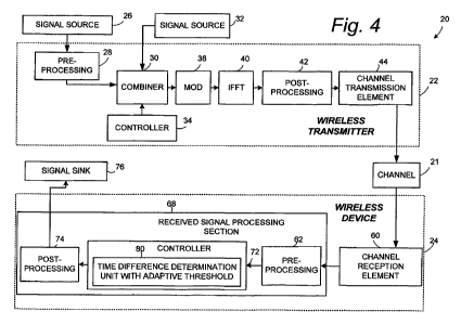
Fig. 4 shows an example, non-limiting embodiment of communication system
wherein transmissions occur over a radio channel 21 from transmitter 22 to
wireless
device 24. The transmitter 22 of communication system 20 of Fig. 4 receives
signals
20 from signal source 26. The signals obtained from source 26 may be of many
types,
such as user data signals (obtained, e.g., from the serving cell) and/or
signals used for
positioning measurement(s). Optionally, and depending on the particular
implementation, transmitter 22 comprises a pre-processing section 28 which can
manipulate the signals obtained from signal source 26 by performing such
optional
functions as serial-to-parallel conversion and channel coding and
interleaving. The
transmitter 22 comprises combiner 30 which combines the signals (which may be
optionally coded and/or interleaved) with other signals such as control
signals,
synchronization signals, framing signals, and pilot signals. In Fig. 4, such
control
signals, synchronization signals, framing signals, and pilot signals are shown
as being
applied or received from another signal source 32.
The combiner 30, which can be a multiplexer or function as a multiplexer,
generates a bit stream by controlled introduction of the signals from source
32 into the
CA 02784040 2012-06-11
WO 2011/073859 PCT/IB2010/055689
13
stream of signals from source 26. Control of introduction of the signals,
including pilot
signals, is achieved by controller 34.
When the transmitter 22 is an orthogonal frequency division multiplexing
(OFDM) transmitter, the bit stream output by combiner 30 is modulated by
modulator
38 onto a series of sub-carriers. As understood by those skilled in the art,
the
modulation performed by modulator 38 essentially maps groups of bits to a
series of
constellation points, represented as complex numbers. A parallel-to-serial
conversion
may be performed on the complex numbers output by modulator 38 prior to
application
to Inverse Fast Fourier Transform (IFFT) unit 40.
The Inverse Fast Fourier Transform (IFFT) unit 40 transforms the modulated
carriers into a sequence of time domain samples. The sequence of time domain
samples output by Inverse Fast Fourier Transform (IFFT) unit 40 may undergo
more
processing functions by an optional post-processor 42. Such post-processing
functions
can include one or more of cyclic extension, windowing, peak control, all of
which are
understood by the person skilled in the art. The resultant OFDM waveform is
applied
to channel transmission element 44. The channel transmission element 44, which
can
be an antenna or antenna system, for example, applies the OFDM waveform (I, Q
output or digital IF signals) to radio channel 21.
One example non-limiting implementation of communication system 20 is in
context of a cellular transmission system in which wireless communications
occur
between a radio access node such as a base station (also called a Node-B or
eNodeB),
for example, and a wireless terminal or mobile unit (often also termed a
mobile station,
a mobile terminal, or a user equipment unit (UE), among other appellations).
In a
wireless system, the wireless terminal, can be embodied in or realized as
mobile
stations such as mobile telephones ("cellular" telephones) and laptops with
mobile
termination, and thus can be, for example, portable, pocket, hand-held,
computer-
included, or car-mounted mobile devices which communicate voice and/or data
with
radio access network. The signal (e.g., the OFDM waveform) is transmitted over
channel 21, which has its own transmission function (as affected by properties
of the
channel and factors such as noise and interference, for example).
Being in a wireless or radio network, the wireless device 24 may be embodied
in or realized by a node of a radio access network (such as a base station
(BS) node or
CA 02784040 2012-06-11
WO 2011/073859 PCT/IB2010/055689
14
an eNodeB, for example) or a wireless terminal (UE). For example, Fig. 4A
illustrates
a situation in which the transmitter 22 is a base station node which transmits
on a
downlink to a wireless device 24 which takes the form of a wireless terminal
(e.g., a
user equipment unit (UE) or mobile station as described above). Fig. 4B
illustrates a
converse situation in which the transmitter 22 is a wireless terminal which
transmits on
an uplink to a wireless device 24 which takes the form of a base station node.
Fig. 4C
illustrates a yet further situation in which both the transmitter 22 and the
wireless
device 24 takes the form of wireless terminals, and in which the technology
disclosed
herein is applicable to both the uplink (UL) and downlink (DL) transmissions.
Fig. 4C
thus illustrates that the technology disclosed herein applies to general
terminal-to-
terminal communication as well, which can be viewed as either uplink (UL) or
downlink (DL) or a mix of downlink (DL) and uplink (UL). Moreover, some
network
nodes, e.g., relay nodes, may also transmit either on the downlink (DL) like a
base
station and on the uplink (UL) like a wireless terminal. Thus, the term
"wireless
device" is employed generically herein to refer to either a wireless terminal
or a radio
access network node or another network node such as a relay node, and which
can
receive information over the radio channel 21 either on the downlink (DL)
[e.g., in the
case of the wireless device being a wireless terminal] or on the uplink (UL)
[e.g., in the
case of the wireless device being a radio access network node].
In the embodiments encompassed herein, such as the non-limiting embodiments
of Fig. 4A, Fig. 4B, and Fig. 4C, it is the wireless device that is being
positioned.
Furthermore, the positioning function may be situated, e.g., either at a core
network
node (e.g., e-SMLC or SLP) in case of network-based positioning or UE-assisted
positioning, or at a wireless terminal, which correspond to UE-based
positioning.
As used herein, a device that is being positioned may either be a receiving
wireless device (e.g. in UE-assisted positioning or UE-based positioning or
with
terminal-to-terminal communication) or a transmitting wireless device (e.g.,
in
network-based positioning or with terminal-to-terminal communication). The
wireless
device being positioned may comprise a UE, a wireless terminal, a small base
station, a
beacon device, a sensor, or other node equipped at least with a radio
interface. It is also
known to the skilled in the art that the positioning functionality may be in
the wireless
device being positioned (e.g. UE-based positioning) or in other network node
(e.g. E-
SMLC or SUPL Location Platform SLP in LTE).
CA 02784040 2012-06-11
WO 2011/073859 PCT/IB2010/055689
Moreover, the techniques described herein apply to all time base methods, not
just Long Term Evolution (LTE), whether uplink or downlink based. For example,
the
technology disclosed herein may apply to other radio access technologies such
as LTE
TDD, LTE FDD, LTE evolutions, WiMAX, and WLAN.
5 Fig. 4 also shows some aspects of the example, non-limiting embodiment of
wireless device 24. The wireless device 24 comprises channel reception element
60,
which can be an antenna or antenna system. The signal received by channel
reception
element 60 (which can be an OFDM waveform with I, Q input or digital IF
signals) as
received by channel reception element 60 is applied to an optional pre-
processing
10 section 62. The pre-processing section 62 removes carrier offset caused by
transmit
and receiver local oscillator differences and selects an appropriate sequence
of samples
to apply to other elements of signal processing section 68.
The received signal processing section 68 comprises controller 72. The
controller 72 serves, e.g., to sort user data signals from non-user data
signals, and to
15 process the non-user data signal. User data signals gated out of controller
72 can be
applied to an optional post-processing section 74. The post-processing section
74 can
perform such functions as channel decoding, de-interleaving, and parallel-to-
serial
conversion, as appropriate. The user data thusly obtained is applied to user
signal sink
76, which can be a voice, text, or other type of application, for example.
Included with
the signals are reference signals which are handled by time difference
determination
unit 80. The reference signals (RF) can be of any appropriate type, such as
Positioning
Reference Signals (PRS) or Common Reference Signals (CRS), for example. The
time
difference determination unit 80, which comprises controller 72, serves, e.g.,
to
determine the presence of the reference signals by comparing correlator
outputs with a
threshold, and further determines the arrival time of the reference signals.
By virtue of
the fact that time difference determination unit 80 adaptively selects its
comparison
threshold in dependence upon noise and interference, the time difference
determination
unit 80 is also referred to as time difference determination unit with
adaptive threshold.
Fig. 5 shows the wireless device 24 from other perspectives, both in terms of
hardware and certain illustrated functionalities of the controller 72
including time
difference determination unit 80. In terms of hardware, Fig. 5 illustrates, as
non-
exhaustive further example components of receiver 24, various input/output
units and
memory 82. The memory 82 can comprise, for example, read only memory (ROM) 84
CA 02784040 2012-06-11
WO 2011/073859 PCT/IB2010/055689
16
and various forms of random access memory (RAM) 86, and can also be used for
storing coded instructions which are executed by controller 72 in conjunction
with
operations described herein. Certain representative input/output units are
illustrated as
being keypad 88; audio input device (e.g. microphone) 90; visual input device
(e.g.,
camera) 92; visual output device (e.g., display 94); and audio output device
(e.g.,
speaker) 96.
Fig. 5 further shows functionalities of time difference determination unit 80
as
comprising receiver 98; correlator 100; reference signal detector 102; noise
and
interference power estimator 104; adaptive threshold selector 106; and
reference signal
analyzer 108. The receiver 98 is connected to receive output from received
signal
processing section 68, e.g., to receive channel-propagated signals from the
radio
channel 21 and to obtain therefrom delayed output signals. The correlator 100
is
connected and configured to use the delayed output signals of the receiver 90
and
replicas of the reference signal to provide correlator output values
indicating a cross-
correlation with the signal received from the radio channel and the replica of
the
reference signal. In particular embodiments, replicas of the reference signal
may be
obtained or reconstructed from the cell identifier (cell ID) which the
wireless device is
supposed to know (e.g., from the assistance data), but in general the replicas
can also be
transmitted, e.g., with the assistance data.
The reference signal detector 102 is connected and configured to receive the
correlator output values from correlator 100, divide these values by the
scaled noise and
interference power estimate obtained from 104, and compare the resulting
values with a
threshold value selected by adaptive threshold selector 106 to detect presence
of a
reference signal, and to estimate an arrival time of the reference signal. To
this end,
Fig. 5 shows reference signal detector 102 as comprising presence detector
section
102A and RS arrival time detection section 102B.
The adaptive threshold selector 106 is connected to the receiver 98 and
configured to at least an estimate of the relative amount of noise and
interference power
in the received signal. The adaptive threshold selector 106 uses the relative
amount of
noise and interference power in the received signal, or at least an estimate
of the
relative amount of noise and interference power in the received signal, to
determine the
adaptive threshold value which it applies to reference signal detector 102. As
used
herein, "at least an estimate" of a particular value or quantity should be
understood to
CA 02784040 2012-06-11
WO 2011/073859 PCT/IB2010/055689
17
encompass not only an estimate of the value or quantity, but a more exacting
determination of the value or quantity as well.
The reference signal analyzer 108 is connected and configured to use at least
the
reference signal (whose presence and arrival time is detected by reference
signal
detector 102) to determine a geographical location of the wireless device 24.
Thus, in
the Fig. 5 embodiment the positioning functionality is in the wireless device
being
positioned (e.g. UE-based positioning). In LTE, location determination in the
wireless
device can be done for so-called UE-based OTDOA positioning, which is not yet
standardized in LTE, or UE-based GNSS.
In other embodiments, the positioning functionality is not in the wireless
device
24 being positioned, but in another network node (e.g. E-SMLC or SUPL Location
Platform SLP in LTE). In such case, the standardized way to determine a
geographical
location of the wireless device is to report the timing measurements
(reference signal
time difference [RSTD]) to the evolved-Serving Mobile Location Center (e-SMLC)
using the LPP protocol, e.g., 3GPP TS 36.355 v9.2.1 June 6, 2010, Evolved
Universal
Terrestrial Radio Access (E-UTRA); LTE Positioning Protocol (LPP), which is
incorporated herein by reference. The currently discussed but not yet
standardized
positioning method using UL timing measurement (UTDOA, UL Time Difference Of
Arrival), which is a network-based positioning method, implies reporting the
measurements over LPPa (LPP Annex) protocol from the radio network node such
as
eNodeB to the positioning node such as E-SMLC or SLP in LTE.
Fig. 5 further shows that the wireless device 24 further comprises a formatter
110 which formats information for transmission from the wireless device 24, as
well as
a transmitted signal processing section 111 which applies signals to be
transmitted to
the channel reception/transmission element(s) 60.
2.0 CORRELATION
In one example embodiment understood with reference to Fig. 6A, correlator
100TD is configured to determine correlation sums in a time domain to use the
correlation sums to derive the correlator output values. In another example
embodiment understood with reference to Fig. 6B, correlator 100FD is
configured to
CA 02784040 2012-06-11
WO 2011/073859 PCT/IB2010/055689
18
determine correlation sums in a frequency domain and to use the correlation
sums to
derive the correlator output values.
2.1 CORRELATION IN THE TIME DOMAIN
The correlator 100TD of Fig. 6A comprises Inverse Fast Fourier Transform
(IFFT) unit 112; Inverse Fast Fourier Transform (IFFT) unit 114; signal
reversal and
conjugation unit 115; Fast Fourier Transform (FFT) unit 116; Fast Fourier
Transform
(FFT) unit 118; element wise multiplication unit 120; Inverse Fast Fourier
Transform
(IFFT) 121 unit; coherent accumulation (complex addition) unit 122; and non-
coherent
accumulation unit 126. The Inverse Fast Fourier Transform (IFFT) unit 112 is
connected and operated to obtain the frequency domain YI(,u) output of
receiver 98 and
to perform an inverse Fast Fourier Transform and thereby provide the time
domain
signal yl(k). The Inverse Fast Fourier Transform (IFFT) unit 114 is connected
and
operated to provide a time domain version sl(k) of the replica of the
reference signal to
signal reversal and conjugation unit 115. Fast Fourier Transform (FFT) unit
116 is then
used to add zero padding and take the Fast Fourier Transform of the output
sl*(-k) of
signal reversal and conjugation unit 115. Fast Fourier Transform (FFT) unit
118 is
used to add zero padding and take the Fast Fourier transform of signal yl(k)
received
from Inverse Fast Fourier Transform (IFFT) 112. The frequency domain outputs
of
Fast Fourier Transform (FFT) unit 116 and Fast Fourier Transform (FFT) unit
118 are
applied to element wise multiplication unit 120, which outputs RI(,u) to
Inverse Fast
Fourier Transform (IFFT) unit 121. Inverse Fast Fourier Transform (IFFT) unit
121
takes the Inverse Fast Fourier transform of signal RI(y) to obtain signal
rl(t), which is
applied to coherent accumulation (complex addition) unit 122. The coherent
accumulation (complex addition) unit 122 in turn outputs the time domain
signal r(t)
[also known as a "time domain correlation sum"] to non-coherent accumulation
unit
(absolute values squared) 126. Non-coherent accumulation unit 126 receives
complex-
valued r(t), takes the absolute square of each term, and sums the result for
all m. The
output of non-coherent accumulation unit 126 is the time domain correlator
output p(t).
As understood from the foregoing and illustrated by Fig. 3, in an example
system and embodiment the reference signal (RS, such as PRS or CRS) can be
transmitted in NAYS consecutive subframes. In the example embodiment the total
number of OFDM symbols containing PRS resource elements over all the
consecutive
subframes is N1.
CA 02784040 2012-06-11
WO 2011/073859 PCT/IB2010/055689
19
The operation of time difference determination unit 80 is now described,
initially in the context of correlator 100TD of Fig. 6A. In the time domain
the signal
can be defined by Equation 1.
s1(k), k = -NP,..., N -1 and l = 0,..., Ni -1 Equation 1
In Equation 1 Nip is the cyclic prefix length and sl(k) is defined by Equation
2.
s1 (k) = s1 (k + N), k = -Np, ... ,-l Equation 2
Let a multipath channel characterized by a discrete finite length time impulse
response be h1 = [h1(0),..., h1 (K -1)] and with h1(i) = 0, i < 0, i >- K.
Then the signal
propagated through the channel can be described by Equation 3.
K-1
y1(k)_Yh1(i)s1(k-i-r)+el(k), k=-NCp,...,N+K+r-2, Equation3
-o
where el(k) is additive complex Gaussian noise with variance No and i is the
propagation delay, for simplicity assumed in the number of samples.
One approach to estimate the arrival time r is to correlate delayed output
signals
yl(k) with replicas of the signal sl(k) in the manner of Equation 4.
Ni -1 N-1
r(t) = y1 (k + t)s1 * (k), t = 0,..., W -1 Equation 4
1-0 k-0
In Equation 4, s1 * (k) is the complex conjugate of the kth sample of signal s
in symbol
l and W is the search window size counted in the number of time samples. The
time-
domain filter of Equation 4 is implemented by signal reversal and conjugation
unit 115;
Fast Fourier Transform (FFT) unit 116; Fast Fourier Transform (FFT) unit 118;
element wise multiplication unit 120; Inverse Fast Fourier Transform (IFFT)
121; and
coherent accumulation (complex addition) unit 122.
CA 02784040 2012-06-11
WO 2011/073859 PCT/IB2010/055689
If sl(k) is a sequence with perfect autocorrelation properties in the manner
of
Equation 5, where PS is the power spectral density of the summed signal, and
6(u) is the
so-called Kronecker delta, defined as 6(u) = 1 for a=0, 6(u) =0 for a#0, then
the
correlation sum as determined by correlator 100 becomes as described in
Equation 6.
N-1
5 Y s1 (k + u)sl * (k) = PS8(u) Equation 5
k-0
Ni -I N-1 (K-1
r(t) Lhl(i)sl(k_i_r+t)+el(k+t)Jsl *(k) _
1-0 k-0 i-0
Ni -1 K-1 Ni -1 N-1 Ni -1
=PS I I h1(i)6(t-c-i) + I I el(k + t)sl*(k) = PS Y h1(t-z) + v Equation 6
1-0 i-0 1-0 k-0 1-0
In Equation 6, the term v can be approximated with a complex Gaussian with
variance
PSN1No. Assuming that h1 (t - r) = h(t - r), l = 0,..., NI -1, the expected
value of the
10 squared absolute value correlator output becomes as set forth by Equation
7.
E~r(t) 2 ) = (NIP h(t - 1_)1)2 + P NINo Equation 7
A detector (e.g., reference signal detector 102A) compares a normalized
correlator output as described by Equation 8 with a threshold 2 and if p (to)>
2 then the
signal is declared as present at time to.
Ir(t) a
15 p(t) = Equation 8
P NINo
In Equation 8, No denotes an estimate of the noise power No.
Assuming a high post-correlation signal to noise ratio (see Equation 9), then
Equation 10 holds true.
(NIPS h(t - z) )~ >> PSNINO Equation 9
CA 02784040 2012-06-11
WO 2011/073859 PCT/IB2010/055689
21
N,Ps h(t - z) 2
p(t) Equation 10
No
In other words, (t) is approximately equal to the SNR including processing
gain PNI.
The estimated arrival time of the first path of the channel is then given by
Equation
11 and deduced by PRS time of arrival detector 102B.
r = min{t}, subject to the constraint p(t) > /I Equation 11
In addition, some measures need to be taken to ensure that the power received
at
time r does not come from a sidelobe from the main peak of the signal. For
example,
with coherent accumulation and a single peak channel the correlation function
will look
like a sine function which has its first sidelobes 13dB lower than the main
peak. So one
criterion can be to exclude peaks which are more than a certain decibel level
(e.g., Z
dB) below the highest peak. Furthermore, some peak interpolation can be
performed to
refine the time estimate. For example, one can take the correlation results -
X),...,
+X) around the peak and use an interpolation formula to get better resolution
of
the peak (e.g., a second-order polynomial fit can be applied and then find the
peak
location of that polynomial. In another extended mode, a center of gravity
approach
can be used.
The selection of the detection threshold 2 in Equation 11 is performed by
adaptive threshold selector 106. As mentioned earlier, in the prior art it was
merely
assumed that the received signal consists of the desired signal plus additive
Gaussian
noise. A deficiency of the prior art assumption is shown by modeling a
situation
wherein it is assumed that the additional noise term is a mix as described by
Equation
26.
e(k) = 1- a i(k) + v(k) Equation 26
In Equation 26 a c [0,I], i(k) is a QPSK modulated signal and v(k) is a
complex
Gaussian signal. The statistics of the correlator described by Equation 8 when
fed with
only Equation 26 as input was investigated with simulations. Fig. 10 shows the
resulting detection thresholds for a particular desired false alarm rate. The
simulated
system is the LTE system utilizing six resource blocks (RBs) and up to four
positioning
CA 02784040 2012-06-11
WO 2011/073859 PCT/IB2010/055689
22
subframes. It can from be seen from Fig. 10 that the detection threshold
varies with
several dBs depending on whether non-Gaussian interference or Gaussian noise
is
dominating.
Among the contrast to prior art practice, the adaptive threshold selector 106
performs an adaptive selection of the threshold and can take into
consideration
interference from other base stations (e.g., eNBs). This interference has
different
characteristics than Gaussian noise and this needs to be accounted for in the
selection of
detection thresholds. Otherwise the number of false alarms may become too
large and
the positioning accuracy will then deteriorate. How adaptive threshold
selector 106
adaptively determines the threshold is subsequently explained below, the
explanation
being applicable both to time difference determination units 80 having
correlators
which operate in the frequency domain and the time domain.
In the receiver 24 of Fig. 5, when operating in LTE the reference signal
(e.g.,
positioning reference signal (PRS)) is specified in the frequency domain, in
the manner
illustrated by Fig. 2. Fig. 2 illustrates only one of four possible PRS
configurations.
Furthermore, much of the baseband processing is done in the frequency domain,
in
particular, the received signal y(k) in Equation 3 is available in the
frequency domain.
Therefore, in another example embodiment of the technology disclosed herein
the
correlation operation is performed (e.g., by correlator 100FD) in the
frequency domain.
Operating in the frequency domain can be beneficial since, in addition, the
estimation
of interference plus noise power can be more conveniently done in the
frequency
domain. Note that an estimate of the noise plus interference power is needed
in
Equation 8.
2.2 CORRELATION IN THE FREQUENCY DOMAIN
Therefore, although the adaptive threshold selector 106 can be utilized with a
correlator such as correlator 100TD of Fig. 6A which operates in the time
domain, in
some embodiments such as that shown in Fig. 6B it is preferable for the
correlator to
operate in the frequency domain.
In an example embodiment the frequency correlator 100FD of Fig. 6B
comprises element wise multiplication unit 220; coherent accumulation (complex
addition) unit 222; Inverse Fast Fourier Transform (IFFT) unit 224; and non-
coherent
CA 02784040 2012-06-11
WO 2011/073859 PCT/IB2010/055689
23
accumulation unit 226. The element wise multiplication unit 220 receives the
frequency domain output signal Yi(,u) from receiver 98 and a frequency domain
reference signal replica (complex conjugated) Sz*(,u) and produces a frequency
domain
product Ri(,u). In an example embodiment the frequency domain product Ri(,u)
of
element wise multiplication unit 220 implements Equation 17. The frequency
domain
product Ri(,u) of element wise multiplication unit 220 is applied to coherent
accumulation (complex addition) unit 222, which yields a summed frequency
domain
product C(,u) [also known as a "frequency domain correlation sum"]. The
operation
of accumulation unit 222 essentially implements Equation 18. The summed
frequency
domain product C(,u) is converted to the time domain summed product signal
r,n(t) by
Inverse Fast Fourier Transform (IFFT) unit 224 in the manner of Equation 19.
The
time domain summed product signal r,n(t) is applied to non-coherent
accumulation unit
226, which provides the correlator output p(k) in the manner of Equation 20.
With regard to frequency domain operation, it is well known that circular
convolution of two sequences is equal to multiplication of the FFTs of the
signals in the
frequency domain. In circular convolution, the linear convolution (1) is
replaced the
expression of Equation 12.
K-1
y, (k) = I h, (i)s, (k - i - ON + el (k), Equation 12
-o
In Equation 12, slON means that the index is taken modulo N. Now due to the
use of
cyclic prefix of length Np, s(-k) = s(N-k), for k=1,..,Np. So as long as K+r <
Np, the
circular convolution (12) is equal to the linear convolution (3).
The Fast Fourier Transform (FFT) X(u) of a sequence x(k) is defined by
1 N-1
X(u) = FFT(x(k)) _ i x(k)e i2 piN, u = 0, ..., N-1. Equation 13
N k-0
With the notation above we can define the FFT of y, (k) in Equation 12 as
Equation 14.
Y (u) = H, (,u)FFT (s, (k - r)) + E, (u) . Equation 14
Another property of FFT is that FFT(x(k - r)) = e-`2721 NX(,u) as long as
CA 02784040 2012-06-11
WO 2011/073859 PCT/IB2010/055689
24
x(k-r)=x(k-r)N, k=0,...,N-1, Equation 15
which is the case for s, (k) due to the use of cyclic prefix (2). Hence
Y (,u) = H, (,t)S1(,i)e-i2=1N + E, (,u) . Equation 16
Now we multiply Equation (16) with the known PRS symbol Si(u), with property
ISi(,u)l = 1 if the lth OFDM symbol has a PRS symbol in subcarrier , S1O = 0
otherwise, so that
R, (,1) = Y, (//)S1 * (,j) = H1(,1)e-i2,,, IN + S, * (,i)E1(,i) Equation 17
if the lth OFDM symbol has a PRS symbol in subcarrier , and R, (,u) = 0
otherwise.
The reference signals typically span several OFDM symbols, so the processing
described above is repeated for all OFDM symbols containing PRS. M segments
each
consisting of an integer number NN of OFDM symbols are coherently added in the
manner of Equation 18.
1 Nc-1
C. (P) = I R(m-1)*L+1 (P)
NP r-o
1 N-1 Equation 18
1 (HI (fe)e i2 calN + S1 * (p)E1(p)~ m = 0,..., M - 1
NP 1-1
In Equation 18, N is the number of coherently accumulated PRS symbols in
subcarrier
. For those OFDM symbols/subcarriers that do not contain PRS, the
corresponding
R( ),is set to zero. For subcarriers that do not contain PRS in any OFDM
symbol,
Cm( ) is set to zero. The time domain equivalent of Cm (p) is obtained by
applying
Inverse Fast Fourier Transform (IFFT) as shown by Equation 19. Equation 19
also
essentially expresses operation of coherent accumulation unit 122 of Fig. 6A.
N-1
rm(t)=IFFT(Cm(,u))=YCm (,u)ei2''`IN,t=0,...,N-1 Equation 19
u-o
The choice of coherent accumulation length NN depends on the speed of the
wireless device. If NN is chosen too large, the channel phase may rotate
during the
measurement. In such a case the terms in the complex sum in Equation 19 starts
to
partly cancel each other. Therefore it may be necessary to stop the coherent
summation
after NN number of OFDM symbols have been added, perform an Inverse Fast
Fourier
CA 02784040 2012-06-11
WO 2011/073859 PCT/IB2010/055689
Transform (IFFT) according to Equation 19, and take the square of the result
to
estimate the accumulated energy. Finally M such non-coherent accumulations are
added. The resulting correlator output can then be written in accordance with
Equation
20. From Equation 20 the person skilled in the art also understands operation
of the
5 non-coherent accumulation unit 126 of correlator 100TD of Fig. 6A.
M-1
p(t) = rm(t) a . Equation 20
M-0
The values of p(t) are compared to a threshold and if any p(t) is larger than
the
threshold then a finer search is done to interpolate the position of the first
peak, e.g. as
10 previously discussed. The existing and the proposed approaches for deriving
the
threshold are discussed below.
3.0 ADAPTIVE THRESHOLD SELECTION
3.1 ADAPTIVE THRESHOLD SELECTION: GAUSSIAN NOISE
Since there is no guarantee that the signal has enough power to be detected,
the
15 threshold should be selected so as to avoid false alarms. Assuming only
Gaussian noise
as input in Equation 19, then the terms
1 Nc-1
rm (t) = IFFT I R(m-1).Nc+l (p)
NP r-o
Equation 21
1 Nc-1
= IFFT ( I (S(m-1)-Nc+l * (JL)E(m-1)-Nc+l (Jr))
NP l-0
are distributed as
m (t) = xre + xim Equation 22
2 0 where Xre and x,m are N(0, ~N1 N0 l2N. )distributed variables representing
the real and
u-o
imaginary parts of the correlation term m (t) , respectively. Hence p(t) in
Equation 20
is the sum of squares of Gaussian variables. This means that 2p(t) l ~Po N0 l
2ND) is
(2M) distributed.
CA 02784040 2012-06-11
WO 2011/073859 PCT/IB2010/055689
26
In order to proceed, an estimate of the noise variance No is needed. By taking
the square of all received samples in the frequencies we obtain the estimate
1 Nl-1Lsym(l)-1 (PI)12 lV~
Nsum ~j ~j lyl v"~0 ,
L l=0 p =0
Equation 23
where l are the frequency indices where there is a PRS symbol in the lth OFDM
symbol and where Lsym(l) is the number of PRS symbols in the lth OFDM symbol.
Here
L is the total number of coherently accumulated reference signal resource
elements. If
we take as detection variable
2(t) = P(t) l tp-o N-11 / 2N Equation 24
u sum
Then, if for any time delay t, 2(t) > A * where * is the detection threshold,
then it is
declared that the signal is present at delay t. (t) in (24) is approximately
distributed as
P(t) 1 v' Equation 25
MIN-'(1/2N )N 2M ' u-o u o
where v- (2M). We can then determine the level of the cumulative distribution
of
(2M) where the probability is 1- Pfa with Pfa as the desired false alarm. Note
that the
noise power No vanished when normalized by the detector variable using
Equation 24.
The desired threshold is then
2"oise * = 1-- chi2inv(l - Pfa,2M) Equation 27
where chi2inv is the inverse of the cumulative distribution function for (2M)
at the
1-Pfa level.
Thus, Equation 27 shows that, in an example embodiment the pure noise
threshold is dependent upon the inverse of the cumulative distribution
function
(2M) at a 1- Pfa level, where M is an integer number of OFDM segments of the
reference signal, and where Pfa is a false alarm value. The suffix "noise"
highlights
that, in this example embodiment, this threshold is applicable when the
additional noise
consists of complex Gaussian white noise only.
CA 02784040 2012-06-11
WO 2011/073859 PCT/IB2010/055689
27
Examples of this outlined timing estimation procedure are shown in Fig. 7-9
for
two different channel models: ETU (which is highly dispersive) and EPA (which
contains only a few paths). The signal is an LTE signal utilizing 6 resource
blocks, i.e.
the Fast Fourier Transform (FFT) size is 128. In Fig. 7-9, the plots show p(t)
(see
Equation 20) for 128 different shifts and the thresholds derived by Equation
25 are
shown as straight lines.
3.2 ADAPTIVE THRESHOLD SELECTION: INTERFERENCE
The threshold given by Equation 27 holds when the noise is purely Gaussian
thermal noise. In reality noise may also be encountered from a strong co-
located
interferer, for example, where the interfering signal is another QPSK
modulated signal.
A model of such an interferer is given by Equation 28.
Y (u) = No I, (u) Equation 28
where No is power of the interfering (assumed flat) channel and I,( ) is the
QPSK
modulated interfering signal.
After correlation we obtain the expression of Equation 29.
R, (fi) = Y (fi)S, * (fi) = No I, (u)S, * (u) = No V, (u) Equation 29
The Equation 29 term V1( ) is a product of two QPSK symbols. QPSK symbols in
LTE
are taken from the symbol alphabet (1N2, -1N2, iN2, -iN2). Therefore the
product of
two QPSK symbols takes values in the set (+1,-1,+i, -i). Following the
procedure and
notation of Section 3.1, the statistics of the detector output as given by
Equation (24)
will be derived assuming only the interferer of Equation (28) as input. To
simplify the
discussion, the statistics is evaluated only for (0), i.e., zero delay. For
this case, the
IFFT operation consists of pure summation. To further simplify (but without
losing
generality) the received QPSK symbols are rotated 45 degrees so that the
constellation
becomes (1N2, -1/'J2, iN2, -iN2). First, the coherent accumulation sum in the
subcarrier domain becomes
CA 02784040 2012-06-11
WO 2011/073859 PCT/IB2010/055689
28
1 Nc-1 NO Nc-1
C. (P) = N I R(m-1)*L+l (P) = N I V(m-1)*L+l (f J) Equation 30
1=0 k 1=0
With reference to Fig. 2, it can be seen that the number of PRS symbols per
subcarrier
per subframe can be either 0, 1 or 2. Therefore N =0, N,./14 or N c/7. Let N1
denote the
total number of PRS symbols from subcarriers containing one PRS symbol per
subframe, and N2 denote the total number of PRS symbols from subcarriers
containing
two PRS symbol per subframe. Summation of (30) over all subcarriers yields the
Inverse Fast Fourier Transform (IFFT) evaluated at t=0. The real part of this
sum is
denoted
7 N2-1
14 N N,-1
rm,Ye (0) = N X1 (1) + N Y X2 (1) Equation 31
c 1-0 c 1-0
where X1, X2 are taken from alphabet (1N2, -1/'J2). Hence
Ki _ Y1=`01 JXi (1)/2 + Ni / 2, i=1,2, are binomially distributed, i.e.,
Pr(Ki = ki) _ N ` = 0.5N= Ni! Ø5 N, i =1,2 Equation 32
ki ki! (Ni - ki )!
Since E~ `01 X. (1) = F2Kj - Ni / Equation 31 can now be rewritten as
(2K1 + K2) - 2 (2N1 + N2 )
m,re (0) = 7 NN0 7 N0
c c
Let K=2K1+K2 and define y = No ((7J / Nc )k - (7,F2 l 2Nc)(2N1 + N2)) .Then
Pr(rm,re (0) = y) = Pr(K = k) _ I P(K1 = k1)P(K2 = k2) Equation 33
2 k, +k2=k
for k = 0,. .. ,2N1 + N2, and where the summation is performed for k1 = 0,...,
N1,
k2 = 0,..., N2.The probability Pr(r Ye (0) =Y2) can now be readily defined to
be
Pr K=k-2N1+ NN+PrIK=k+2N,+ +N2)N k:# 2N1+ N2
Pr(r 2 (0) = y 2) = Equatio
m,re Pr K= 2N1 +N2 k= 2N1 +N2
2 2
n 34
CA 02784040 2012-06-11
WO 2011/073859 PCT/IB2010/055689
29
The probability Pr(rr Ye (0) = y2) in Equation 34 can thus be explicitly
computed for
y2 =No((7,F2 /Ne)k-(7V/2Ne)(2N,+N2))2,k=0,...,2N,+N2.
It is easy to realize that rn ,m (0) has the same probability distribution
function as rn2ye (0) .
Next note that since rm Ye (0) and rm,m (0) are independent and of zero mean,
the detector
variable (24) can be rewritten as a sum
M-1
2(0) = p(0)l(MNoIP-o(1/2Nr))_ (rm(0)1 l(MNoIr-o(1/2Nr))_
M-0
M-1
2 _~ (r 2 (0) + r (0))l (NoMIr-o (1 / 2Nr ))
M-0
Equation 35
where the statistics of each term r2 (0),r2 (0) can be determined using
Equation 32 -
Equation 34.
The probability density function of the sum of two random variables can be
obtained by convolving the density functions. Convolution is then repeated
until the
distribution of 2M summations is obtained. The corresponding cumulative
density
function is denoted as FQpsK(x; M,NN,NI,N2), where the dependence on the
parameters
M, NN, NI and N2 has been explicitly stated. The threshold value corresponding
to the
1-Pfa value can now be determined as
2QPSK * = FQPsK (1- P fa ; M,Ne,N1,N2) Equation 36
Equation 36 thus shows that, in an example embodiment, the pure interference
threshold is dependent upon the expression 2QPSK * = FQPSK (1- Pfa;
M,NC,N,,N2), where
M is an integer number of OFDM segments of the reference signal, each segment
consisting of Nc number of OFDM symbols, wherein Nc is an integer accumulation
length of the reference signal, wherein NI is the total number of PRS symbols
from
subcarriers containing one PRS symbol per subframe, wherein N2 denote the
total
number of PRS symbols from subcarriers containing two PRS symbol per subframe.
wherein FQPSK(1- Pfa;M,Nc,N1,N2) is a cumulative density function dependent
upon (I-
Pfa), and wherein Pfa is a false alarm value. The suffix "QPSK" that is used
to highlight
CA 02784040 2012-06-11
WO 2011/073859 PCT/IB2010/055689
that this threshold is applicable when the additional noise consists of a QPSK
modulated interferer only.
3.3 ADAPTIVE THRESHOLD SELECTION: a ESTIMATION
To finally decide a threshold, a noise weight factor a used in Equation 26
5 should be estimated. To calculate an estimate of a, the fourth moment of
e(k) is
examined. As used herein, e(k) is the same as the "received signal" in the
time or
frequency domain, e.g., the received channel-propagated signal received from
the radio
channel. For a Gaussian variable E I e(k) 14 = 2N02 , whereas for QPSK symbols
E I e(k) 14= Noe . As detection variable the adaptive threshold selector 106
calculates
10 an estimate of the normalized fourth moment of e(k) as follows:
1 1 Y (f~l) 4 E e(k) 4
z = 1'P a . Equation 37
Y (PI) 2 (Ee(k)2)2
1
,P
In Equation 37, the summation is over all frequency indices l where there is a
PRS
symbol in the lth OFDM symbol (compare with Equation 23). The relation between
z
15 and can be shown to be
z= 1+2 2 Equation 38
so that an estimate of a is the first root to the quadratic Equation 38, i.e.
which lies in
the interval [0,1 ],
20 & =1- 2 _-z Equation 39
Using the estimate of z, the estimated noise weight factor is obtained. Using
the
estimated , the adaptive threshold selector 106 can select the adaptive
threshold, e.g. by
linear interpolation between the pure noise threshold nO15e (Equation 27) and
the pure
25 interference threshold QPSK (Equation 36). In general, the pure noise
threshold is
CA 02784040 2012-06-11
WO 2011/073859 PCT/IB2010/055689
31
defined based on the assumption that all the received interference and noise
consist of
random signals (following the Gaussian distribution in the described example),
whilst the
pure interference threshold is defined based on the assumption that the all
the received
interference noise and interference comprise of signals of a known modulation
(QPSK in
the described example). The adaptive threshold selector 106 obtains the
adaptive
threshold in accordance with Equation 39a.
2adaptive = (ix.ise + (1- GL')/LQPSK Equation 39a
The interpolation can also be made in the logarithmic domain, e.g., by
converting the
linear threshold power values into decibel values.
The thresholds noise* and QPSK* can be computed by the adaptive threshold
selector 106 at the same time as the positioning measurements are being
performed.
Alternatively, all thresholds can be computed offline and stored in memory for
possible
values of M, Ne, N1, N2 and Pfa. As a further option, appropriate threshold
values for
varying values of , M, Ne, N1, N2 and Pfa can be precomputed, e.g., by means
of
simulations as illustrated in Fig. 10, and stored in memory and made available
to the
adaptive threshold selector 106.
Alternatively, an explicit formula for the fractional noise/interference case
can be
derived, e.g., by scaling and convolving a quantized Gaussian distribution
with the
distribution defined by Equation 33.
The performance of the estimator of the noise weight factor a is shown in Fig.
11, which shows that a can be accurately estimated in most cases.
3.4 ADAPTIVE THRESHOLD SELECTION: CHOICE OF FALSE ALARM
RATE
One final aspect is the choice of false alarm rate Pfa. Note that Pfa is an
input
variable to the threshold calculations according to Equation 25 and as
described above.
The value of Pfa depends, e.g., on the number of eNBs the UE is ordered to
measure
and the amount of initial uncertainty in the expected timing.
CA 02784040 2012-06-11
WO 2011/073859 PCT/IB2010/055689
32
Assume that the target is that the probability that at least one measurement
out
of nCeiis is corrupt is Pfpos. This is given by
Pfpos = -(1-Pf~g)nCells ^ ncells Pf~g Equation 40
Assuming that the UE has to search W delays, the per delay probability Pfa can
now be determined as
Pfa - Pfpos/ (ncells W) . Equation 41
The uncertainty in the signal arrival time at the UE location can be analyzed
by
considering the geometry in Fig. 12. UE is apriori located in a cell with
distance A
from the eNB 1. This information is known, e.g. through the use of Timing
Advance to
synchronize the UE transmissions. Note that it is not known whether the UE is
at
position A or position B in Fig. 12. Assume that signals are transmitted from
eNBI and
eNB2 at time to.
Given speed of light c, the signals from eNBI and eNB2 arrive through a line-
of-sight path at position A at times ti and t2, respectively:
t, = to + A Equation 42
C
t2 = to + d + A . Equation 43
C
If UE is at B, then the signals arrive at times:
t, =t0 + A Equation 44
C
t2 = to + d - A Equation 45
C
Assume eNB 1 is the serving cell to which the distance is known due to Timing
Advance mechanism. Given ti, it is possible to predict the signal arrival time
from
eNB2 in order to minimize the code phase search. Note that for
CA 02784040 2012-06-11
WO 2011/073859 PCT/IB2010/055689
33
position A: t2 = tl - 0 + d + 0 = t1 + d, Equation 46
C C C
position B: t2 = t, - A + d - 0 = t, + d - 20 . Equation 47
C C C
As a result,
t2 E [ti + d - 20 , t1 + d ] . Equation 48
C C C
The width of the time of arrival uncertainty window is thus
tun = 2A Equation 49
C
The UE thus has to search over
W = 2A= 1 Equation 50
c TS
different shifts, where Ts is the sampling interval.
4.0 MODELING AND SIMULATIONS
The proposed scheme for time of arrival estimation using LTE Positioning
Reference Signals (PRS) was evaluated by means of system simulations. The
system
simulation assumptions were as listed in 3GPP TSG-RAN WG4 Meeting #52bis, R4-
094089, Miyazaki, Japan, October 12 - October 16, 2009, which is incorporated
herein
by reference. Three detection threshold schemes were tested, the scheme based
on
Gaussian noise ('noise') as described in Section 3. 1; the QPSK interference
based
method from Section 3.2 ('qpsk'); and the adaptive scheme outlined in Section
3.3
('adaptive').
Fig. 13 illustrates results for a Case 1. Case 1 is characterized by an inter-
site
distance of 500 m. The network is synchronized. For Case 1, the QPSK-based
threshold is the best with the adaptive one being very close in performance.
The noise-
based scheme is slightly worse for ETU and significantly worse for EPA. This
seems
to suggest that there is a relatively high probability to have one strong
interferer in this
synchronized scenario.
CA 02784040 2012-06-11
WO 2011/073859 PCT/IB2010/055689
34
Fig. 14 illustrates results for a Case 3. Case 3, which is characterized by an
inter-site distance of 1732 m. Also in Case 3, the QPSK-based and the adaptive
ones
are the best and the noise-based method slightly worse. Also in this case it
is likely that
one strong interferer appears relatively often.
Fig. 15 illustrates results for the Case 1, but where the network is not
synchronized and where the positioning frames are only partially aligned. In
this case,
it turns out that the QPSK-based method is the worst, whereas the noise-based
and the
adaptive scheme perform equally well. In this case, the interference comes
from
multiple base stations and therefore the sum of interference terms appear more
like
noise.
To summarize, the presented results confirm that the adaptive scheme offers
the
best compromise when the interference situation is varying.
The technology disclosed herein does not exclude and is intended to encompass
the case that positioning measurements can be conducted on reference signals
other
than (PRS), since the technology disclosed herein is also applicable, for
example, for
the case when Common Reference Signals (CRS) are measured.
5.0 EXAMPLE ADVANTAGES
The technology disclosed herein concerns method and apparatus to derive
adaptive detection thresholds based on analysis of the interferer/noise
characteristics.
The technology disclosed herein provides both reduction of false alarms and
increased
detection probability compared to the case where fixed (state-of-the-art)
thresholds are
used. False alarms due to strong interferers are reduced by increasing the
detection
thresholds when it is detected that one strong interferer is dominating. When
the signal
is corrupted by noise only, the thresholds are lowered, hereby enabling
detection of
weak signals.
Except that optimizing uniform thresholds for a real network is a tedious
task,
the technology disclosed herein is particularly important for non-uniform and
heterogeneous environments where reference signals from many cells can be
detectable
by the wireless device in at least some parts of the network and the detection
threshold
cannot be configured to be uniform for the entire network due to non-uniform
cell
CA 02784040 2012-06-11
WO 2011/073859 PCT/IB2010/055689
sizes, various propagation conditions, etc. This can be significant for
reference signals
used for positioning a wireless device such as a wireless terminal where
timing
measurements need to be taken for more than three base stations and the
network
typically ensures good hearability of the signals from multiple base stations.
5 Although described for PRS, the technology disclosed herein is not limited
to
PRS or any particular reference signal or positioning in general, neither to
downlink or
uplink. Other examples of signals can e.g. be cell-specific reference signals,
sounding
reference signals, synchronization signals, etc. Also, although described for
QPSK, the
disclosed main principles in the methodology are not limited to a particular
modulation
10 scheme. The techniques described herein apply to all time base methods, not
just Long
Term Evolution (LTE), whether uplink or downlink based. For example, the
technology disclosed herein may apply to other radio access technologies such
as LTE
TDD, LTE FDD, LTE evolutions, WiMAX, and WLAN. The proposed solution is thus
relevant for signal detection in general. Moreover, the technology and
embodiments
15 described herein also apply to any measurement techniques, e.g., timing
measurements
such as RSTD derived from time of arrival measurement performed using the
adaptive
threshold.
The reference signal time difference (RSTD) is a time difference of arrival
between reference signals from two different base stations. The RSTD can
20 be calculated by computing the difference of two time of arrival
measurements (each
determined using Equation 11). For example, the reference signal time
difference
(RSTD) may be a relative timing difference between the neighbour cell j and
the
reference cell i, defined as TsubframeRx_j - TsubframeRxi, where:
TsubframeRx_j is the time when
the UE receives the start of one subframe from cell j TsubframeRxi is the time
when the
25 UE receives the corresponding start of one subframe from cell i that is
closest in time to
the subframe received from cell j. The reference point for the observed
subframe time
difference is taken as the antenna connector of the UE. See, e.g., 3GPP TS
36.214,
section 5.1.12.
Although the description above contains many specificities, these should not
be
30 construed as limiting the scope of the invention but as merely providing
illustrations of
some of the presently preferred embodiments. It will be appreciated that the
scope of
the present invention fully encompasses other embodiments which may become
obvious to those skilled in the art and thus that the scope is not to be
unduly limited.
CA 02784040 2012-06-11
WO 2011/073859 PCT/IB2010/055689
36
Reference to an element in the singular is not intended to mean "one and only
one"
unless explicitly so stated, but rather "one or more." All structural and
functional
equivalents to the elements of the above-described embodiments that are known
to
those of ordinary skill in the art are expressly incorporated herein and are
intended to
be encompassed hereby. Moreover, it is not necessary for a device or method to
address each and every problem sought to be solved by the present invention,
for it to
be encompassed hereby.