Note: Descriptions are shown in the official language in which they were submitted.
CA 2784454 2017-04-12
81658722
- 1 -
FAIL-TO-NEUTRAL SYSTEM AND METHOD FOR A
TOROIDAL TRACTION DRIVE AUTOMATIC TRANSMISSION
CROSS-REFERENCE TO RELATED APPLICATION
[0001] This patent application claims priority to, and the benefit of,
U.S. Patent
Application Ser. No. 61/287,045, filed December 16, 2009.
Field Of The Invention:
[0002] The present invention relates generally to toroidal traction
drive automatic
transmissions including a variator, and more specifically to systems and
methods for
automatically controlling the transmission to a neutral state upon detection
of variator
and/or clutch related failures.
BACKGROUND
[0003] Toroidal traction drive automatic transmissions may include a
variator, one
or more gear sets and a number of selectively engageable friction devices that
cooperate
together to transfer drive torque from a power plant to one or more loads. It
is desirable to
monitor operation of one or more of these devices and to command the
transmission to a
neutral state upon detection of one or more specified faults or failure
conditions.
SUMMARY
[0004] The present invention may comprise one or more of the features
recited in
the attached claims, and/or one or more of the following features and
combinations
thereof. A fail-to-neutral diagnostic method for a transmission including a
variator may
comprise monitoring a state of a pressure differential valve fluidly coupled
to a high side
pressure applied to at least one actuator coupled to at least one
corresponding roller of the
variator and also fluidly coupled to a low side pressure applied to the at
least one actuator,
determining from the state of the pressure differential valve a variator
torque sign
corresponding to whether torque transferred by the at least one roller is
positive or
negative, determining an expected variator torque sign based on current
operating
conditions of the transmission, and
CA 02784454 2012-06-14
WO 2011/075317
PCT/US2010/058704
- 2 -
commanding the transmission to a true neutral condition if the determined
variator
torque sign is different from the expected variator torque sign.
[0005] The pressure differential valve may comprise a spool having one end
fluidly coupled to the high-side pressure and an opposite end fluidly coupled
to the
low-side pressure. The variator torque sign may have one value when the high-
side
pressure is sufficiently greater than the low-side pressure and may have an
opposite
value when the low-side pressure is sufficiently greater than the high-side
pressure.
Determining from the state of the pressure differential valve a variator
torque sign
may comprise determining the variator torque sign based on a position of the
spool
relative to the pressure differential valve and. A pressure switch may be
fluidly
coupled to the pressure differential valve, and may be configured to assume
one
state when the high-side pressure is sufficiently greater than the low-side
pressure to
cause the spool to move to one extreme relative to the pressure differential
valve,
and to assume an opposite state when the low-side pressure is sufficiently
greater
than the high-side pressure to cause the spool to move to an opposite extreme
relative to the pressure differential valve. Determining from the state of the
pressure
differential valve a variator torque sign may comprise determining the
variator torque
sign from the state of the pressure switch. The variator torque sign may have
one
value when the pressure switch has assumed the one state and may have an
opposite value when the pressure switch has assumed the opposite state. The
expected variator torque sign may have the one value if the pressure switch is
expected to be in the one state, and may have the opposite value if the
pressure
switch is expected to be in the opposite state. Commanding the transmission to
a
true neutral condition may comprise commanding the transmission to the true
neutral
condition if the variator torque sign is the one value and the expected
variator torque
sign is the opposite value, and if the variator torque sign is the opposite
value and
the expected variator torque sign is the one value.
[0006] The method may further comprise logging a fault code in a memory
unit if the determined variator torque sign is different from the expected
variator
torque sign.
[0007] A fail-to-neutral diagnostic system for a transmission including a
variator may comprise a pressure differential valve fluidly coupled to a high
side
pressure applied to at least one actuator coupled to the variator and also
fluidly
CA 02784454 2012-06-14
WO 2011/075317 PCT/US2010/058704
- 3 -
coupled to a low side pressure applied to the at least one actuator, a
pressure switch
fluidly coupled to the pressure differential valve and configured to assume
one of two
opposite states depending upon which of the high-side and low-side pressures
is
greater than the other, and a control circuit. The control circuit may include
a
memory having instructions stored therein that are executable by the control
circuit
to determine from current operating conditions of the transmission an expected
state
of the pressure switch, to determine an actual state of the pressure switch
and to
command the transmission to a true neutral condition if the actual state of
the
pressure is different from the expected state of the pressure switch.
[0008] The pressure switch may be configured to assume one state if the
high-side pressure is sufficiently greater than the low-side pressure and to
assume
an opposite state if the low-side pressure is sufficiently greater than the
high-side
pressure. The instructions stored in the memory may include instructions that
are
executable by the control circuit to determine that the expected state of the
pressure
switch is the one state if the high-side pressure is expected to be
sufficiently greater
than the low-side pressure and is the opposite state if the low-side pressure
is
expected to be sufficiently greater than the high-side pressure. The
instructions
stored in the memory may further include instructions that are executable by
the
control circuit to command the neutral state if the pressure switch has
assumed the
one state and the expected state of the pressure switch is the opposite state,
and to
command the neutral state if the pressure switch has assumed the opposite
state
and the expected state of the pressure switch is the one state. The
instructions
stored in the memory may further include instructions that are executable by
the
control circuit to log a fault code in a memory unit if the determined actual
state of
the pressure switch is different from the expected state of the pressure
switch.
[0009] A fail-to-neutral diagnostic method for a transmission including a
variator may comprise monitoring operating states of a plurality of clutch
control
valves each fluidly coupled to a corresponding gear engagement clutch of the
transmission, determining expected operating states of each of the plurality
of clutch
control valves based on current operating conditions of the transmission, and
forcing
the transmission to a true neutral condition if a monitored operating state of
at least
one of the plurality of clutch control valves is different from a
corresponding one of
the expected operating states.
CA 02784454 2012-06-14
WO 2011/075317
PCT/US2010/058704
- 4 -
[0010] The transmission may have a plurality of operating modes each
operable in a different road speed ranges of a vehicle carrying the
transmission.
Determining expected operating states of each of the plurality of clutch
control valves
may comprise determining which of the plurality of operating modes the
transmission
is currently operating in, and determining the expected operating states of
each of
the plurality of clutch control valves for the current operating mode of the
transmission based on the current operating conditions of the transmission.
The
method may further comprise a plurality of pressure switches each fluidly
coupled to
a different one of the plurality of clutch control valves and each configured
to assume
an operating state depending upon the operating state of a corresponding one
of the
plurality of clutch control valves. Monitoring operating states of a plurality
of clutch
control valves may comprise monitoring operating states of each of the
plurality of
pressure switches. Determining expected operating states of each of the
plurality of
clutch control valves may comprise determining expected operating states of
each of
the plurality of pressure switches.
[0011] The method may further comprise logging a fault code in a memory
unit if a monitored operating state of at least one of the plurality of clutch
control
valves is different from a corresponding one of the expected operating states.
Logging a fault code may comprise including in the fault code information
indicative
of a current one of a plurality of different operating modes of the
transmission.
Logging a fault code may further comprise including in the fault code
information
identifying which of the plurality of clutch control valves has a monitored
operating
state that is different from a corresponding expected operating state.
[0012] A fail-to-neutral diagnostic system for a transmission including a
variator may comprise a plurality of clutch control valves each fluidly
coupled to a
corresponding gear engagement clutch of the transmission, a plurality of
pressure
switches each fluidly coupled to a different one of the plurality of clutch
control
valves, and a control circuit. The control circuit may include a memory having
instructions stored therein that are executable by the control circuit to
determine from
the plurality of pressure switches actual operating states of each of the
plurality of
clutch control valves, to determine expected operating states of each of the
plurality
of clutch control valves based on current operating conditions of the
transmission,
and to force the transmission to a true neutral condition if an actual
operating state of
CA 02784454 2012-06-14
WO 2011/075317
PCT/US2010/058704
- 5 -
at least one of the plurality of clutch control valves is different from a
corresponding
one of the expected operating states.
[0013] Each of the plurality of pressure switches may be configured to
assume
an operating state depending upon the operating state of a corresponding one
of the
plurality of clutch control valves. The instructions stored in the memory may
include
instructions that are executable by the control circuit to determine from the
plurality
of pressure switches actual operating states of each of the plurality of
clutch control
valves by monitoring operating states of each of the plurality of pressure
switches,
and to determine expected operating states of each of the plurality of clutch
control
valves by determining expected operating states of each of the plurality of
pressure
switches. The transmission may have a plurality of operating modes each
operable
in a different road speed ranges of a vehicle carrying the transmission. The
instructions stored in the memory may include instructions that are executable
by the
control circuit to determine expected operating states of each of the
plurality of clutch
control valves by determining which of the plurality of operating modes the
transmission is currently operating in, and then determining the expected
operating
states of each of the plurality of clutch control valves for the current
operating mode
of the transmission based on the current operating conditions of the
transmission.
[0014] The instructions stored in memory may include instructions that are
executable by the control circuit to log a fault code in the memory if an
actual
operating state of at least one of the plurality of clutch control valves is
different from
a corresponding one of the expected operating states. The instructions stored
in
memory may further include instructions that are executable by the control
circuit to
include in the fault code information indicative of a current one of a
plurality of
different operating modes of the transmission. The instructions stored in
memory
may further include instructions that are executable by the control circuit to
include in
the fault code information identifying which of the plurality of clutch
control valves
has an actual operating state that is different from a corresponding expected
operating state.
CA 02784454 2012-06-14
WO 2011/075317 PCT/US2010/058704
- 6 -
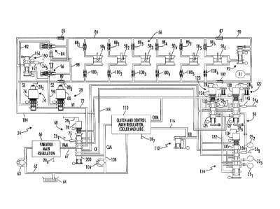
BRIEF DESCRIPTION OF THE DRAWINGS
[0015] FIG. 1 is a block diagram of one illustrative embodiment of a
system for
controlling operation of a toroidal traction drive automatic transmission
including fail-
to-neutral controls.
[0016] FIG. 2A is a diagram illustrating operation of one illustrative
embodiment of a variator that forms part of the toroidal traction drive
automatic
transmission illustrated in FIG. 1.
[0017] FIG. 2B is a diagram further illustrating operation of the variator
of FIG.
2A.
[0018] FIG. 3 is a schematic diagram of one illustrative embodiment of the
electro-hydraulic control system that forms part of the toroidal traction
drive
automatic transmission illustrated in FIG. 1.
[0019] FIG. 4 is a flowchart of one illustrative embodiment of a process
for
monitoring certain fault states of the electro-hydraulic control system of
FIG. 3 and
commanding true neutral upon detection of at least some of the fault states.
[0020] FIG. 5 is a table of expected valve pressure states for the various
operating modes of the transmission.
[0021] FIG. 6 is a magnified view of the fault valve illustrated in FIG. 3
showing one operating state thereof.
[0022] FIG. 7 is another magnified view of the fault valve illustrated in
FIG. 3
showing an opposite operating state thereof.
[0023] FIG. 8 is a magnified view of the sign valve illustrated in FIG. 3
showing one operating state thereof.
[0024] FIG. 9 is another magnified view of the sign valve illustrated in
FIG. 3
showing an opposite operating state thereof.
DESCRIPTION OF THE ILLUSTRATIVE EMBODIMENTS
[0025] For the purposes of promoting an understanding of the principles of
the
invention, reference will now be made to a number of illustrative embodiments
shown in the attached drawings and specific language will be used to describe
the
same.
[0026] Referring now to FIG. 1, a block diagram is shown of one
illustrative
embodiment of a system 10 for controlling operation of a toroidal traction
drive
CA 02784454 2012-06-14
WO 2011/075317
PCT/US2010/058704
- 7 -
automatic transmission 14. In the illustrated embodiment, a power plant or
energy
center 12 is coupled to an automatic transmission 14 such that a rotatable
output
shaft 16 of the power plant 12 is coupled to a rotatable input shaft 18 of the
transmission 14 in a conventional manner. The input shaft 18 is coupled, in
the
illustrated embodiment, to a combination variator and gear set 20 that further
includes a plurality of selectively engageable friction devices, e.g., one or
more
conventional, selectively engageable clutches or the like, and an output of
the
combination variator and gear set 20 is coupled to a rotatable output shaft
22. The
combination variator and gear set 20 is illustratively controlled by an
electro-
hydraulic control system 24, some of the details of which will be described in
greater
detail hereinafter.
[0027] The power plant 12 is generally an apparatus that produces
rotational
drive power at the output shaft 16. Examples of the power plant 12 include,
but
should not be limited to, one or any combination of a one or more engines,
such as
an internal combustion engine of the spark ignited, compression ignition or
other
variety, a steam engine, or type of engine that produces mechanical energy
from one
or more other fuel sources, one or more electrical generators, and the like.
[0028] The combination variator and gear set 20 illustratively includes a
conventional full-toroidal, traction-drive variator that is coupled to a
conventional gear
set. Referring to FIGS. 2A and 2B, one illustrative embodiment of some of the
structural features of such a full-toroidal, traction-drive variator 40 is
shown. In the
illustrated embodiment, the variator 40 includes a pair of opposing, toroidal-
shaped
disks 42 and 44 that rotate independently of each other. For example, the disk
42 is
rigidly coupled to the input shaft 18 of the transmission 14 such that the
disk 42 is
rotatably driven by the power plant 12. The disk 44 is rigidly coupled to an
output
shaft 46 of the variator 40, and is rotatably coupled to the shaft 18 such
that the disk
44 rotates freely about the shaft 18. The output shaft 46 of the variator 40
is coupled
directly, or indirectly through one or more transmission gears, to the output
shaft 22
of the transmission 14 such that output shaft 46 of the variator 40 drives one
or more
wheels of a vehicle (not shown) carrying the power plant 12 and transmission
14.
[0029] A number of rollers 48 are illustratively positioned between
opposing
inner, arcuate-shaped surfaces of the disks 42 and 44, and a traction fluid
(not
shown) is disposed between the rolling surface of each such roller 48 and the
inner
CA 02784454 2012-06-14
WO 2011/075317 PCT/US2010/058704
- 8 -
surfaces of the disks 42 and 44. In the illustrated embodiment, the rolling
surfaces of
the various rollers 48 therefore do not contact, in a structural sense, the
inner
surface of either disk 42, 44; rather torque is transmitted by the various
rollers 48
between the two disks 42, 44 via the traction fluid. It is because torque is
transferred
between the two disks 42, 44 via the traction fluid and not via structural
contact
between the rolling surfaces of the rollers 48 and the arcuate inner surfaces
of the
disks 42, 44 that the variator is referred to as a traction-drive apparatus.
[0030] In the embodiment illustrated in FIGS. 2A and 2B, two such rollers
481
and 482 are shown operatively positioned between the opposing inner surfaces
of
the two disks 42, 44. A roller actuator 501, e.g., in the form of a
conventional
hydraulically actuated piston, is coupled to the roller 481 via a bracket 521,
and
another roller actuator 502, e.g., in the form of another conventional
hydraulically
actuated piston, is coupled to the roller 482 via a bracket 522. It will be
understood
that the brackets 521 and 522 do not represent rotatable shafts about which
the
rollers 481 and 482 may be rotatably driven. Rather, the brackets 521 and 522
represent structures about which the rollers 481 and 482 rotate. In one actual
implementation, for example, the brackets 521 and 522 are configured to attach
to the
central hub of the rollers 481 and 482 on either side thereof such that the
brackets
521 and 522 and actuators 501 and 502 would extend generally perpendicular to
the
page illustrating FIGS. 2A and 2B.
[0031] The hydraulically controlled actuators 501 and 502 are each
illustratively
controllable, by selectively controlling a high-side hydraulic pressure
applied to one
side of the actuator and a low-side hydraulic pressure applied to the opposite
side of
the actuator, to thereby control torque transferred from a corresponding
roller 481,
482 relative to the inner, annular surfaces of the two disks 42, 44. The
actuators 501
and 502 illustratively control driveline torque rather than the position or
pitch of the
rollers 481 and 482. The rollers 481 and 482 are free-castoring, and are
responsive to
the actuators 501 and 502 to seek a position that provides the correct ratio
match of
engine and drive train speeds based on input energy equaling output energy.
[0032] In one illustrative implementation, the variator 40 includes two
sets of
disks 42 and 44, with the pairs of the disks 42 rigidly coupled to each other
and with
the pairs of the disks 44 also rigidly coupled to each other, such that the
embodiment
illustrated in FIGS. 2A and 2B represents one-half of such an implementation.
In this
CA 02784454 2012-06-14
WO 2011/075317 PCT/US2010/058704
- 9 -
illustrative implementation, three rollers are positioned between each
opposing set of
disks 42, 44 for a total of six rollers 481 ¨ 486 and six corresponding
hydraulically
controlled actuators 501 ¨ 506. It will be understood, however, that this
particular
implementation of the variator 40 is shown and described only by way of
example,
and that other embodiments of the variator 40 that include more or fewer pairs
of
disks 42, 44, that include more or fewer rollers 48 and hydraulically
controlled
actuators 50, and/or that are configured to be only partially toroidal in
shape, may
alternatively be used. It will further be understood that while the operation
of the
variator 40 illustrated and described herein as being generally hydraulically
controlled, this disclosure contemplates embodiments in which operation of the
variator 40 is controlled via purely electronic or electro-mechanical
structures.
[0033] Referring again to FIG. 1, the gear set within the combination
variator
and gear set 20 illustratively includes one or more conventional planetary
gear set(s)
and/or other gear set(s) that define(s) at least two automatically selectable
gear
ratios and that is coupled to, or integrated with, the variator, e.g., the
variator 40
illustrated and described with respect to FIG. 2. The combination variator and
gear
set 20 further illustratively includes a number of conventional friction
devices, e.g.,
clutches, which may be selectively controlled to thereby control shifting of
the
transmission 14 between the two or more gear ratios. In alternate embodiments,
the
gear set may include more than one planetary gear set, one or more planetary
gear
sets in combination with one or more other conventional gear sets, or
exclusively
one or more non-planetary gear sets.
[0034] In the example embodiment illustrated in FIG. 1, the transmission14
includes three friction devices, e.g., in the form of three conventional
clutches Cl, C2
and C3. In this embodiment, each clutch Cl, C2 and C3 is operated in a
conventional manner by fluid pressure under the control of the electro-
hydraulic
control system 24. In this regard, a fluid path 251 is fluidly coupled between
the
electro-hydraulic control system 24 and the clutch Cl, a fluid path 252 is
fluidly
coupled between the electro-hydraulic control system 24 and the clutch C2, and
a
fluid path 253 is fluidly coupled between the electro-hydraulic control system
24 and
the clutch C3. The gear set and the clutches Cl, C2 and C3 are illustratively
arranged to provide four separate modes of operation of the transmission14,
and the
CA 02784454 2012-06-14
WO 2011/075317
PCT/US2010/058704
- 10 -
various operating mode of the transmission 14 are selectively controlled by
the
operation of the clutches Cl, 02 and 03.
[0035] In a first
operating mode, Ml, for example, the clutch Cl is applied,
e.g., engaged, while the clutches C2 and 03 are released, e.g., disengaged,
and in
this mode forward or reverse launch can be accomplished, and the vehicle
carrying
the transmission 14 can be operated at vehicle speeds up to about 10 miles per
hour. In a second operating mode, M2, as another example, the clutch 02 is
engaged while the clutches Cl and C3 are disengaged, and in this mode the
vehicle
can be operated at vehicle speeds in the range of about 10-30 miles per hour.
In a
third operating mode, M3, as yet another example, the clutch 03 is engaged
while
the clutches Cl and C2 are disengaged, and in this mode the vehicle can be
operated at vehicle speeds greater than about 30 miles per hour. In a fourth
mode,
MO, as a final example, the clutches Cl, C2 and 03 are all disengaged, and in
this
mode the transmission 14 is in so-called "true neutral." In the transitional
states
between the various operating modes Ml, M2 and M3, the variator torque is
illustratively reversed to assist transitions from one operating mode to the
next.
[0036] The system
10 further includes a transmission control circuit 30 that
controls and manages the overall operation of the transmission 14. The
transmission control circuit 30 includes a number, M, of operating parameter
inputs,
01 ¨ OPm, that
are electrically connected to corresponding operating parameter
sensors included within the electro-hydraulic control system 24 via
corresponding
signal paths 261¨ 26m, wherein M may be any positive integer. The one or more
operating parameter sensors included within the electro-hydraulic control
system 24,
examples of which will be described hereinafter, produce corresponding
operating
parameter signals on the signal paths 261¨ 26m, which are received by the
transmission control circuit 30. The transmission 14 further includes a
number, N, of
electrically controllable actuators included within the electro-hydraulic
control system
24 that are each electrically connected to a different one of a corresponding
number
of actuator control outputs, AC1¨ ACN of the transmission control circuit 30
via
corresponding signal paths 281¨ 28N, wherein N may be any positive integer.
The
one or more electrically controllable actuators included within the electro-
hydraulic
control system 24, examples of which will be described hereinafter, are
responsive to
actuator control signals produced by the transmission control circuit 30 on
the
CA 02784454 2012-06-14
WO 2011/075317 PCT/US2010/058704
- 1 1 -
corresponding signal paths 281¨ 28N to control various operational features of
the
transmission 14.
[0037] Illustratively, the transmission control circuit 30 is
microprocessor-
based, and includes a memory unit 32 having instructions stored therein that
are
executable by the control circuit 30 to control operation of the transmission
14
generally, and more specifically to control operation of the electro-hydraulic
control
system 24 as will be described herein. It will be understood, however, that
this
disclosure contemplates other embodiments in which the transmission control
circuit
30 is not microprocessor-based, but is configured to control operation of the
transmission 14 generally and operation of the electro-hydraulic system 24
more
specifically, based on one or more sets of hardwired instructions and/or
software
instructions stored in the memory unit 32.
[0038] Referring now to FIG. 3, a schematic diagram is shown of one
illustrative embodiment of the electro-hydraulic control system 24 of FIG. 1.
In the
illustrated embodiment, the electro-hydraulic control system 24 is roughly
divided in
two separate control sections; a variator control section 56 and a clutch
control
section 58. A conventional fluid pump 60 is configured to supply transmission
fluid,
e.g., conventional transmission oil, to the variator control section 56 from a
source 64
of transmission fluid, e.g., a conventional transmission sump. In the
illustrated
embodiment, a fluid inlet of the fluid pump 60 fluidly coupled to the sump 64
via a
fluid passageway 62. A fluid outlet of the pump 60 is fluidly coupled to an
inlet of a
variator main regulation block 66, and one of the output signal paths 286 of
the
control circuit 30 is electrically connected to the variator main regulation
block 66.
The variator main regulation block 66 includes conventional components, e.g.,
one
or more valves, responsive to a control signal produced on the signal path 286
by the
transmission control circuit 30 to supply pressure-regulated transmission
fluid at a
fluid outlet of the block 66 in a conventional manner.
[0039] The fluid outlet of the variator main regulation block 66 is fluidly
coupled to a fault valve 68 via a variator main fluid path 67 (VAM), and
another one
of the output signal paths 281 of the control circuit 30 is electrically
connected to an
electronic actuator 70, e.g., a conventional solenoid, of the fault valve 68.
The fault
valve 68 is configured to be responsive to a control signal produced on the
signal
path 281 by the transmission control circuit 30 to control operation of the
fault valve
CA 02784454 2012-06-14
WO 2011/075317 PCT/US2010/058704
- 12 -
68 between a stroked position and an unstroked position as will be described
in
greater detail hereinafter. A variator fluid path 72 is fluidly coupled
between the fault
valve 68 and fluid inlets of two separate variator trim valves 74 and 78. For
purposes of this document, the fluid path 72 may be referred to herein as a
variator
fluid (VF) supply path.
[0040] The variator trim valves 74 and 78 each include an actuator 76 and
80
respectively that is electrically connected to the transmission control
circuit 30 via a
signal path 282 and 283 respectively. A fluid outlet of the variator trim
valve 74 is
fluidly coupled to a high-side fluid inlet of the variator control section 56
of the
electro-hydraulic control system 24 via a fluid path 82, and a fluid outlet of
the
variator trim valve 78 is fluidly coupled to a low-side fluid inlet of the
variator control
section 56 of the electro-hydraulic control system 24 via a fluid path 94. For
purposes of this document, the fluid paths 82 and 94 may be referred to herein
as Si
and S2 respectively.
[0041] In the illustrated embodiment, the actuators 76 and 80 are
illustratively
conventional electronically actuated solenoids, and the trim valves 74 and 78
are
illustratively variable-bleed valves that produce variable-pressure
transmission fluid
at their fluid outlets based on control signals produced by the transmission
control
circuit 30 on the signal paths 282 and 283 respectively. The transmission
control
circuit 30 thus controls the fluid pressures within the Si and S2 fluid paths
from the
VF fluid path (connected to the fault valve 68) via electronic control of the
trim valves
74 and 78 respectively.
[0042] The Si fluid path (82) is fluidly coupled to one end of a
conventional
damper 84, an opposite end of which is fluidly coupled to a variator high-side
fluid
passageway 86. In the embodiment illustrated in FIG. 3, the variator includes
six
actuators, 501 - 506, e.g., conventional pistons, and the variator high-side
fluid
passageway 86 is fluidly coupled to one side, e.g., a high side, of each such
actuator
501 ¨ 506 via a corresponding conventional damper 881 ¨ 886. A conventional
check
valve 85 is interposed between the variator high-side fluid passageway 86 and
a
control main (COM) fluid path 104, and another conventional check valve 87 is
interposed between the variator high-side fluid passageway 86 and an endload
fluid
passageway 90.
CA 02784454 2012-06-14
WO 2011/075317
PCT/US2010/058704
- 13 -
[0043] The S2
fluid path (94) is similarly fluidly coupled to one end of another
conventional damper 96, an opposite end of which is fluidly coupled to a
variator low-
side fluid passageway 98. The variator low-side fluid passageway 98 is fluidly
coupled to an opposite side, e.g., a low side, of each actuator 501¨ 506 of
the
variator via a corresponding conventional damper 1001-1006. A conventional
check valve 89 is interposed between the variator low-side fluid passageway 98
and
the control main (COM) fluid path 104, and another conventional check valve
102 is
interposed between the variator low-side fluid passageway 98 and the endload
fluid
passageway 90. The endload fluid passageway 90 is fluidly coupled to an
endload
relief valve 92, which is further fluidly coupled between the high side and
the low side
of the actuator 506. Further details relating to one illustrative structure
and method of
operating the endload relief valve 92 are provided in co-pending U.S. Patent
Application Serial No. 61/287,020, having Attorney Docket No. 46582-209632
(ATP-
0047-USP), the disclosure of which is incorporated herein by reference in its
entirety.
[0044] Another conventional fluid pump 106 is configured to supply
transmission fluid from the sump 64 to the clutch control section 58 of the
electro-
hydraulic control system 24. In the illustrated embodiment, a fluid inlet of
the fluid
pump 106 fluidly coupled to the sump 64 via the fluid passageway 62, and fluid
outlet
of the pump 106 is fluidly coupled to the fault valve 68 and to a fluid inlet
of a clutch
and control main regulation, cooler and lube block 110 via a fluid passageway
108.
Another one of the output signal paths 287 of the control circuit 30 is
electrically
connected to the clutch and control main regulation, cooler and lube block
110. The
clutch and control main regulation, cooler and lube block 110 includes
conventional
components, e.g., one or more valves, responsive to a control signal produced
on
the signal path 287 by the transmission control circuit 30 to supply pressure-
regulated transmission fluid to a clutch main, CLM, fluid passageway 108 and
to a
control main, COM, fluid passageway 104 in a conventional manner. The control
main fluid passageway 104 is further fluidly coupled to the fault valve 68. An
exhaust backfill valve 113 establishes an exhaust backfill pressure, EB, in an
exhaust backfill fluid passageway 116 that is also fluidly coupled to the
clutch and
control main regulation, cooler and lube block 110 and to the fault valve 68.
The
clutch and control main regulation, cooler and lube block 110 further includes
CA 02784454 2012-06-14
WO 2011/075317
PCT/US2010/058704
- 14 -
conventional components for cooling and filtering the transmission fluid and
for
providing lubrication paths to the variator and to the various gears of the
gear set.
[0045] The clutch main fluid passageway, CLM, is fluidly coupled to the
fault
valve 68, and a clutch fluid, CF, passageway 118 is fluidly coupled between
the fault
valve 68 and pair of clutch trim valves 120 and 122. Generally, the fault
valve 68 is
configured to be responsive to a control signal produced on the signal path
281 by
the transmission control circuit 30 to control operation of the fault valve 68
to
selectively supply and inhibit transmission fluid operating pressure to the
variator
control section 56 and to the clutch control section 58 of the electro-
hydraulic control
system 24 as will be described in detail hereinafter.
[0046] The clutch trim valves 120 and 122 each illustratively include an
electronic actuator, e.g., an electrically controlled solenoid, 126 and 128
respectively
that is electrically connected to the transmission control circuit 30 via a
signal path
284 and 285 respectively. A fluid inlet of each clutch trim valve 120 and 122
is fluidly
coupled to the control main, COM, fluid passageway 104. Each valve 120 and 122
is responsive to a control signal produced by the transmission control circuit
30 on
the signal path 284 and 285 respectively to selectively apply or block the
control main
pressure, COM, to a control end of a spool 125 and 127 respectively carried by
each
valve 120 and 122. Each clutch trim valve 120 and 122 is further fluidly
coupled to
the exhaust backfill pressure, EB, passageway 116 and to the clutch fluid, OF,
passageway 118. The clutch trim valve 122 is further fluidly coupled to the C2
clutch
fluid path 252, and the clutch trim valve 122 is illustratively responsive to
a control
signal supplied by the transmission control circuit 30 to the actuator 128 on
the
signal path 285 to selectively activate, i.e., engage, and deactivate, i.e.,
disengage,
the clutch C2 via the clutch fluid path 252. For example, in the diagram
illustrated in
FIG. 3, the clutch trim valve 122 is shown in its deactivated state in which
the control
end of the spool 127 fed by the actuator 128 is exhausted such that the spool
127 of
the valve 122 fluidly couples the clutch fluid path 252 to the exhaust
backfill, EB,
pressure passageway 116, thereby deactivating or disengaging the clutch C2. In
its
activated state, the actuator 128 would feed the control main pressure, COM,
to the
control end of the spool 127 thereby causing the spool 127 to move downwardly
(in
FIG. 3) and fluidly couple the clutch fluid path 252 to the clutch fluid, CF,
passageway
118, thereby activating or engaging the clutch 02.
CA 02784454 2012-06-14
WO 2011/075317 PCT/US2010/058704
- 15 -
[0047] The clutch trim valve 120 is further fluidly coupled to a clutch
multiplex
valve 124 via a fluid passageway 132. The clutch multiplex valve 124
illustratively
includes an electronic actuator, e.g., an electrically controlled solenoid,
134 that is
electrically connected to the transmission control circuit 30 via a signal
path 286. A
fluid inlet of the clutch multiplex valve 124 is fluidly coupled to the
control main,
COM, fluid passageway 104, and the clutch multiplex valve 124 is responsive to
a
control signal produced by the transmission control circuit 30 on the signal
path 286
to selectively apply or block the control main pressure, COM, to a control end
of a
spool 135 carried by the valve 124. The clutch multiplex valve 124 is further
fluidly
coupled to the exhaust backfill pressure, EB, passageway 116 and to the Cl
clutch
fluid path 25 and the C3 fluid path 253.
[0048] The clutch trim valve 120 is illustratively responsive to a control
signal
supplied by the transmission control circuit 30 to the actuator 126 on the
signal path
284 to selectively supply clutch fluid, CF, from the clutch fluid passageway
118 or
exhaust backfill pressure, EB, from the exhaust backfill passageway 116 to the
clutch multiplex valve 124. For example, in the diagram illustrated in FIG. 3,
the
clutch trim valve 120 is shown in its activated state in which the control end
of the
spool 125 fed by the actuator 126 is fed by the control main pressure, COM,
such
that the spool 125 of the valve 120 fluidly couples the fluid path 132 to the
clutch
fluid, CF, fluid passageway 118, thereby supplying clutch fluid pressure, CF,
to the
clutch multiplex valve 124. In its deactivated state, the actuator 126 would
exhaust
the control end of the spool 125 thereby causing the spool 125 to move
upwardly (in
FIG. 3) and fluidly couple the fluid passageway 132 to the exhaust backfill,
EB, fluid
passageway 116, thereby supplying exhaust backfill pressure, EB, to the clutch
multiplex valve 124.
[0049] The clutch multiplex valve 124 is illustratively responsive to a
control
signal supplied by the transmission control circuit 30 to the actuator 134 on
the
signal path 286 to selectively couple the fluid passageway 132 to either the
Cl clutch
fluid path 251 or the C3 clutch fluid path 253, to thereby activate, i.e.,
engage, and
deactivate, i.e., disengage, the clutch Cl via the clutch fluid path 251 or
the clutch 03
via the clutch fluid path 253. For example, in the diagram illustrated in FIG.
3, the
clutch multiplex valve 124 is shown in its deactivated state in which the
control end
of the spool 135 fed by the actuator 134 is exhausted such that the spool 135
of the
CA 02784454 2012-06-14
WO 2011/075317 PCT/US2010/058704
- 16 -
valve 124 fluidly couples the C1 clutch fluid path 251 to the fluid path 132.
If the trim
valve 120 is in its activated position as illustrated in FIG. 3, the Cl clutch
fluid path
251 will thus be fluidly coupled to the clutch fluid, CF, passageway 118,
thereby
activating or engaging the C1 clutch. At the same time, the valve 124 fluidly
couples
the C3 clutch fluid path 253 to the exhaust backfill, EB, fluid passageway 116
to
thereby deactivate or disengage the C3 clutch. If, on the other hand, the trim
valve
120 is in its deactivated position, the exhaust backfill, EB, pressure
passageway 116,
will be fluidly coupled to the Cl clutch fluid path 251 and to the C3 clutch
fluid path
253, thereby deactivating or disengaging both of the clutches Cl and C3.
[0050] If instead the clutch multiplex valve 124 is in its activated state
in which
the control end of the spool 135 fed by the actuator 134 is fluidly coupled to
the
control main, COM, fluid passageway 104, the spool 135 of the valve 124
fluidly
couples the 03 clutch fluid path 253 to the fluid path 132. If the trim valve
120 is in its
activated position as illustrated in FIG. 3, the C3 clutch fluid path 253
would thus be
fluidly coupled to the clutch fluid, CF, passageway 118, thereby activating or
engaging the C3 clutch, and at the same time, the valve 124 would fluidly
couple the
Cl clutch fluid path 251 to the exhaust backfill, EB, fluid passageway 116 to
thereby
deactivate or disengage the Cl clutch. If, on the other hand, the trim valve
120 is in
its deactivated position, the exhaust backfill, EB, pressure passageway 116,
will be
fluidly coupled to the Cl clutch fluid path 251 and to the C3 clutch fluid
path 253,
thereby deactivating or disengaging both of the clutches Cl and 03.
[0051] In the embodiment illustrated in FIG. 3, the variator section 156
of the
electro-hydraulic control system 24 further includes a pressure differential
valve 150
including a spool 154 that is fluidly coupled at one end to the Si fluid
passageway
82, i.e., the high-side pressure of the variator actuators 501 ¨ 506, and at
its opposite
end to the S2 fluid passageway 94, i.e., the low-side pressure of the variator
actuators 501¨ 506. The pressure differential valve 150 is further fluidly
coupled to
the control main, COM, fluid passageway 104.
[0052] In the illustrated embodiment, sensors are operatively positioned
relative to each of the valves 68, 120, 122, 124 and 150 to enable monitoring
of the
operating states of each of these valves 68, 120, 122, 124 and 150. In one
illustrative embodiment, the sensors are provided in the form of conventional
pressure switches, although it will be understood that a conventional pressure
CA 02784454 2012-06-14
WO 2011/075317
PCT/US2010/058704
- 17 -
sensor may be substituted for any one or more of the pressure switches. In any
case, each of the pressure switches is electrically connected to the
transmission
control circuit 30 to allow monitoring by the transmission control circuit 30
of the
states of the pressure switches and thus the operating states of the valves
68, 120,
122, 124 and 150. In the embodiment illustrated in FIG. 3, for example, a
pressure
switch 75 is fluidly coupled to the fault valve 68, and is electrically
connected to the
transmission control circuit 30 via one of the signal paths 261. Another
pressure
switch 130 is fluidly coupled to the trim valve 120, and is electrically
connected to the
transmission control circuit 30 via one of the signal paths 262. Still another
pressure
switch 136 is fluidly coupled to the multiplex valve 124, and is electrically
connected
to the transmission control circuit 30 via one of the signal paths 263. Yet
another
pressure switch 142 is fluidly coupled to the trim valve 122, and is
electrically
connected to the transmission control circuit 30 via one of the signal paths
264.
Another pressure switch 152 is fluidly coupled to the pressure differential
valve 150,
and is electrically connected to the transmission control circuit 30 via one
of the
signal paths 265. The transmission control circuit 30 is operable to process
the
signals produced by the pressure switch 75, 130, 136, 142 and 152 in a known
manner to determine corresponding operating states, i.e., whether activated or
deactivated, of the various valves 68, 120, 122, 124 and 150.
[0053] Referring now to FIG. 4, a flowchart is shown of one illustrative
embodiment of a process 160 for monitoring the statuses of the various
pressure
switches 75, 130,136, 142 and 152 and commanding true neutral upon detection
of
certain pressure switch failures or faults, and logging or storing any
detected
pressure switch failure or fault. The term "true neutral" is defined for
purposes of this
document as an operating condition of the transmission in which none of the
clutches C1-C3 is activated or engaged, and corresponds to a transmission
operating mode MO identified and described hereinabove. The process 160 is
illustratively stored in the memory 32 of the transmission control circuit 30
in the form
of instructions that are executable by the transmission control circuit 30 to
carry out
the operations of the process 160 as will be described in detail hereinafter.
[0054] The process 160 begins at step 162, and thereafter at step 164 the
transmission control circuit 30 is operable to determine the present operating
mode,
OM, of the transmission 14. Generally, as described hereinabove, the
transmission
CA 02784454 2012-06-14
WO 2011/075317
PCT/US2010/058704
- 18 -
14 is operable in one of three non-neutral operating modes, M1 ¨ M3, and the
operating mode of the transmission 14 at any given instant in time will depend
primarily on the road speed of the vehicle carrying the transmission 14.
Because the
transmission control circuit 30 controls and manages the overall operation of
the
transmission 14, the transmission control circuit 30 will generally have
knowledge at
any given time of the current operating mode, OM, of the transmission 14. The
transmission control circuit 30 thus executes step 164 by determining
internally the
current operating mode, OM, of the transmission 14. Thereafter at step 166,
the
transmission control circuit 30 is operable to determine the status of each
pressure
switch 75, 130, 136, 142 and 152, e.g., by sampling and processing the
pressure
switch signals produced by the pressure switches on the corresponding signal
paths
261¨ 265.
[0055] Following
step 166, the process 160 advances to step 168 where the
transmission control circuit 30 is operable to compare the status of the
pressure
switches, determined at step 166, with expected pressure switch statuses based
on
the current operating mode of the transmission 14. Illustratively, a table or
other
form of expected pressure switch status values by transmission operating mode
is
stored in the memory 32, and the transmission control circuit 30 executes step
168
by comparing the pressure switch statuses determined at step 166 with such a
table
or other form of expected pressure switch status values stored in the memory
32.
Referring to FIG. 5, an example is shown of one such expected pressure switch
status table 190 that lists expected pressure switch status values for each of
the
three operating modes of the transmission.
[0056] Returning
again to FIG 4, the process 160 advances from step 168 to
step 170 where the transmission control circuit 30 determines based on the
comparison of step 168 whether a fault or failure associated with the fault
valve 68 is
detected. As illustrated in the pressure switch status table 190 of FIG. 5,
the
pressure switch 75 is expected to have a value of "1" for each of the three
operating
modes, M1 ¨ M3, of the transmission 14. Thus, if the comparison at step 168
reveals that the actual value of the pressure switch 75 is "1," then the
transmission
control circuit 30 determines at step 170 that no fault valve fault is
detected, and the
process 160 advances to step 172. Otherwise, the transmission control circuit
30
determines at step 170 that a fault valve fault exists and the process 160
advances
CA 02784454 2012-06-14
WO 2011/075317
PCT/US2010/058704
- 19 -
to step 178 where the transmission control circuit 30 stores or logs an
appropriate
fault code in the memory 32.
[0057] At step 172 the transmission control circuit 30 determines based on
the
comparison of step 168 whether a fault or failure associated with the clutch
valves
120, 122 and 124 is detected. As illustrated in the pressure switch status
table 190
of FIG. 5, the pressure switches 136, 130 and 142 are expected to have the
values
"0 1 0" respectively for mode 1, the values "0 0 1" respectively for mode 2
and the
values "1 1 0" respectively for mode 3. If the comparison at step 168 reveals
that the
actual values of the pressure switches 136, 130 and 142 match the expected
values
for the current operating mode of the transmission 14, then the transmission
control
circuit 30 determines at step 172 that no clutch valve fault is detected, and
the
process 160 advances to step 174. Otherwise, the transmission control circuit
30
determines at step 172 that a clutch valve fault exists and the process 160
advances
to step 176 where the transmission control circuit 30 commands true neutral.
Illustratively, the transmission control circuit 30 is operable to command
true neutral
by deactivating or destroking the fault valve 68, thereby forcing the
transmission 14
to a true neutral condition if at least one of the actual values of the
pressure switches
136, 130 and 142 is different from a corresponding one of the expected values
of the
pressure switches 136, 130 and 142.
[0058] Referring now to FIGS. 6 and 7, magnified views of the fault valve
68
are shown in which FIG. 6 illustrates the fault valve 68 in its activated or
stroked
position (as also illustrated in FIG. 3), and in which FIG. 7 illustrates the
fault valve
68 in its deactivated or unstroked position. In its activated or stroked
position
illustrated in FIG. 6, the spool 200 is forced by the control main pressure,
COM,
applied to its control end 202 to be positioned within the fault valve 68 to
cause the
variator main pressure, VAM, to be fluidly coupled to the variator fluid (VF)
passageway 116, to cause the clutch main pressure, CLM, to be fluidly coupled
to
the clutch fluid, CF, passageway 118 and to cause the control main pressure,
COM,
to be fluidly coupled to the pressure switch 75 such that the pressure switch
75
produces a logic high signal, or "1." In this normally activated or stroked
position, the
fault valve 68 thus feeds the variator main pressure, VAM, to the two variator
trim
valves 74 and 78 via the fluid passageway 72, and feeds the clutch main
pressure,
CA 02784454 2012-06-14
WO 2011/075317 PCT/US2010/058704
- 20 -
CLM, to the two clutch trim valves 120 and 122 via the fluid passageway 118
(see
FIG. 3).
[0059] In its deactivated or unstroked position illustrated in FIG. 7, the
control
end 202 of the spool is exhausted and the spool 200 is thereby forced to be
positioned within the fault valve 68 to cause the control main pressure, COM,
to be
fluidly coupled to the variator fluid (VF) passageway 116, to cause the
exhaust
backfill pressure, EB, to be fluidly coupled to the clutch fluid, CF,
passageway 118
and to cause the exhaust backfill pressure, EB, to also be fluidly coupled to
the
pressure switch 75 such that the pressure switch 75 produces a logic low
signal, or
"0." In this deactivated or unstroked position, the fault valve 68 thus feeds
the
control main pressure, COM, to the two variator trim valves 74 and 78 via the
fluid
passageway 72, and feeds the exhaust backfill pressure, EB, to the two clutch
trim
valves 120 and 122 via the fluid passageways 116 and 118. Referring again to
FIG.
3, with the exhaust backfill pressure, EB, supplied to the fluid path 118,
none of the
clutches Cl ¨ C3 can be activated or engaged regardless of the operating
states of
any of the clutch valves 120, 122 and 124, and the transmission 14 is thereby
in the
true neutral state.
[0060] Referring again to FIG. 4, the process 160 advances from step 176
to
step 178 where the transmission control circuit 30 stores or logs an
appropriate fault
code in the memory 32, i.e., a fault code appropriate for a clutch valve fault
or failure.
The stored or logged fault code may include information only as to the
existence of a
clutch valve fault or failure, information relating to which transmission
operating
mode was active, i.e., mode 1, 2 or 3, when the clutch valve fault or failure
was
detected, information relating to the specific pressure switch for which the
fault or
failure was detected, and/or whether the clutch valve failure or fault
occurred
because the monitored state of the pressure switch in question was a "1" when
a "0"
was expected or vice versa.
[0061] At step 174 the transmission control circuit 30 determines, based on
the comparison of step 168, whether a fault or failure associated with the
pressure
differential valve 150 is detected. As illustrated in the pressure switch
status table
190 of FIG. 5, the pressure switch 152 may have a value of "1" or "0" in each
of the
three operating modes. Referring now to FIGS. 8 and 9, magnified views of the
pressure differential valve 150 are shown illustrating the two opposite states
of the
CA 02784454 2012-06-14
WO 2011/075317
PCT/US2010/058704
- 21 -
pressure switch 152. In FIG. 8, for example, which is also the state of the
valve 150
illustrated in FIG. 3, the spool 154 is driven upwardly, indicating that the
pressure S2
is greater than that of Si, which means that the low-side pressure applied to
the
variator actuators 501¨ 502 via the fluid passageway 98 is greater than the
high-side
pressure applied to the variator actuators 501 ¨ 506 via the fluid passageway
86. In
this position, the spool 154 fluidly couples the pressure switch 152 to
exhaust, and in
this position the pressure switch 152 thus produces a logic low signal or "0."
In FIG.
9, in contrast, the spool 154 is driven downwardly, indicating that the
pressure Si is
greater than that of S2, which means that the high-side pressure applied to
the
variator actuators 501¨ 506 via the fluid passageway 86 is greater than the
low-side
pressure applied to the low-side pressure applied to the variator actuators
501¨ 506
via the fluid passageway 98. In this position, the spool 154 fluidly couples
the
pressure switch 152 to the control main pressure, COM, and in this position
the
pressure switch 152 thus produces a logic high signal or "1." Illustratively,
the
pressure differential valve 150 is designed to have a specified amount of
hysteresis
between the switching states of the pressure switch 152, and in one embodiment
the
hysteresis is approximately 15-20% such that the differential pressure between
Si
and S2 must be greater than about15-20% before the pressure switch 152 changes
state. Those skilled in the art will appreciate that this hysteresis value is
provided
only by way of example and that other hysteresis values, or no hysteresis
value, may
alternatively be used.
[0062] As with
the operating modes, M1 ¨ M3, the transmission control circuit
30 likewise controls and manages the operation of the variator, and the
transmission
control circuit 30 thus has knowledge of whether the operating torque of the
variator
is positive or negative at any given instant in time based on current
transmission
operating conditions. Illustratively, a positive operating torque of the
variator occurs
when the differential pressure valve 150 is positioned such that the pressure
switch
152 produces a "1," e.g., as illustrated in FIG. 9, and a negative operating
torque of
the variator occurs when the differential pressure valve 150 is positioned
such that
the pressure switch 152 produces a "0," e.g., as illustrated in FIG. 8,
although the
pressure differential valve may alternatively be designed such that the
pressure
switch 152 produces a "1" during periods of negative variator torque and
produces a
"0" during periods of positive variator torque. The transmission control
circuit 30 can
CA 02784454 2012-06-14
WO 2011/075317 PCT/US2010/058704
- 22 -
thus determine from the state of the pressure differential valve, e.g., from
the state of
the pressure switch 152, a variator torque sign corresponding to whether
torque
transferred by the at least one roller to the variator is positive or
negative. Because
the transmission control circuit 30 has knowledge of whether the operating
torque of
the variator is positive or negative, the transmission control circuit 30
accordingly has
knowledge of the expected value of the pressure switch 152 at any instant in
time.
If, at step 168, the comparison reveals that the actual value of the pressure
switch
152 matches the expected value of the pressure switch 152, then the
transmission
control circuit 30 determines at step 174 that no pressure differential valve
fault is
detected, and the process 160 loops back to step 164. Otherwise, the
transmission
control circuit 30 determines at step 174 that a pressure differential valve
fault exists
and the process 160 advances to step 176 where the transmission control
circuit 30
commands true neutral as described hereinabove. Thereafter at step 178, the
transmission control circuit 30 stores or logs a fault code corresponding to a
differential pressure valve fault or failure. The stored or logged fault code
may
include information only as to the existence of a differential pressure valve
fault or
failure, and/or may include information relating to whether the differential
pressure
valve fault or failure occurred because the monitored state of the pressure
switch
152 was a "1" when a "0" was expected or vice versa.
[0063] While the invention has been illustrated and described in detail in
the
foregoing drawings and description, the same is to be considered as
illustrative and
not restrictive in character, it being understood that only illustrative
embodiments
thereof have been shown and described and that all changes and modifications
that
come within the spirit of the invention are desired to be protected.