Note: Descriptions are shown in the official language in which they were submitted.
CA 02784633 2012-08-01
21643CA/EL/AP
1
AUXILIARY DEVICE FOR THE INSTALLATION OF PLATE-SHAPED
PRODUCTS FOR COVERING FLOORS AND/OR WALLS
The present invention relates to an auxiliary device for the installation of
plate-
shaped products for covering floors and/or walls.
It is known that during laying and installation operations of plate-shaped
products on floors and/or walls, such as tiles, bricks, sheets or the like, it
is
usually necessary to position the plate-shaped products at a reciprocal
relative
distance.
For this purpose, spacing devices are usually used, made up of cross-shaped, T-
shaped or other-shaped plastic bars, which are suitable for ensuring the
correct
reciprocal positioning of the tiles.
If on the one hand however, such spacing devices make it possible to position
the plate-shaped products very precisely with respect to their reciprocal
arrangement on the surface to be covered, on the other, it cannot but be noted
that they do not also ensure the perfect coplanarity of the top surfaces
(i.e., the
visible surfaces) of the installed plate-shaped products.
It must be remembered in fact that the surface to be covered is not always
perfectly level, the thickness of the plate-shaped products cannot be constant
from tile to tile and the layer of adhesive placed in between the surface to
be
covered and the plate-shaped products can show some lack of uniformity.
For all these reasons, the plate-shaped products tend to take up a position
which
is not perfectly level and the user is inconveniently forced to correct the
height
of each single plate-shaped product using specific equipment and great skill.
In this respect, it must be added that the need for perfect coplanarity of the
surface is particularly felt when very regular and perfectly smoothed plate-
shaped products are used because in this case the absence of positioning
uniformity, even minor, appears immediately clear.
In this respect, from the document IT 1 334 260, the use is known of a spacing
device which, besides spacing out the ceramic products, allows ensuring level
installation.
Such device comprises a series of flat fins, suitable for creating ceramic
product
supporting areas, and an arc which stands perpendicular to the flat fins and
CA 02784633 2012-08-01
,
21643CA/EL/AP
2
which is shaped so as to allow the stable and forced insertion and positioning
of
a tapered-profile element between the arc itself and the underlying tiles.
During installation, the tiles are tightened between the underlying fins and
the
tapered-profile element which is forcibly blocked under the arc.
This spacing device also has drawbacks however including the fact that the
insertion and the coupling of the tapered-profile element in the space below
the
arc is not always practical and easy.
Furthermore, to ensure the necessary stability of the tapered-profile element
and
prevent it from releasing itself during installation, thus compromising the
installation operation of the plate-shaped products, the tapered-profile
element
must be forcibly pushed underneath the arc and the user is not always able to
apply such force without the inconvenient use of special pliers or other
tools.
The main aim of the present invention is to provide an auxiliary device for
the
installation of plate-shaped products for covering floors and/or walls with
which
it is possible, in a practical, easy and functional way, to ensure the exact
coplanarity of the plate-shaped products.
Another object of the invention is to provide an auxiliary device for the
installation of plate-shaped products for covering floors and/or walls with
which
it is possible to simplify the laying and installation operations of plate-
shaped
products.
Not the last object of the present invention is to provide an auxiliary device
for
the installation of plate-shaped products for covering floors and/or walls
which
can be used without using special pliers or other tools.
Another object of the present invention is to provide an auxiliary device for
the
installation of plate-shaped products for covering floors and/or walls which
allows to overcome the mentioned drawbacks of the state of the art within the
ambit of a simple, rational, easy and effective to use as well as low cost
solution.
The above objects are achieved by the present auxiliary device for the
installation of plate-shaped products for covering floors and/or walls,
comprising:
- at least a first element having:
CA 02784633 2012-08-01
21643CA/EL/AP
3
- a substantially flat base body for supporting at least two adjacent
plate-
shaped products and
- a gripping body which is associated substantially at right angles with
said base body, said base body being suited to support said plate-shaped
products from opposite sides of said gripping body;
- at least a second element associable with said gripping body for
fastening
said plate-shaped products between said base body and said second element
to define the coplanarity of said plate-shaped products;
characterized by the fact that said first element and said second element
comprise screw connection means suited to allow the coupling by screwing of
said second element on said first element around a rotation axis substantially
at
right angles to said base body.
Other characteristics and advantages of the present invention will become more
evident from the description of some preferred, but not sole, embodiments of
an
auxiliary device for the installation of plate-shaped products for covering
floors
and/or walls, illustrated purely as an example but not limited to the annexed
drawings in which:
Figure 1 is an exploded view of a preferred embodiment of the device according
to the invention;
Figures 2a and 2b show, in a succession of views from above, the screwing of
the device of figure 1;
Figure 3 is an axonometric view of the device of figure 1 during the
installation
of two plate-shaped products;
Figure 4 is a section view of the device of figure 1 during the installation
of two
plate-shaped products;
Figure 5 is another section view of the device of figure 1 during the
installation
of two plate-shaped products;
Figure 6 is a section view similar to that of figure 5 during the installation
of
two plate-shaped products with different thickness;
Figure 7 is an exploded view of an alternative embodiment of the device
according to the invention;
Figure 8 is an axonometric view of the device of figure 7 during the
installation
CA 02784633 2012-08-01
21643CA/EL/AP
4
of two plate-shaped products.
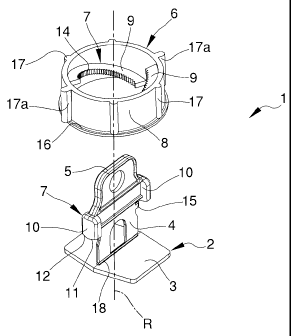
With particular reference to the embodiment shown in figures from 1 to 6,
globally indicated by 1 is an auxiliary device for the installation of plate-
shaped
products for covering floors and/or walls.
The device 1 comprises a first element 2 substantially made in a single body
and
comprising:
- a substantially flat base body 3 on which at least two adjacent plate-
shaped
products M can be rested and
- a gripping body 4, which is associated at right angles with the base body
3.
The gripping body 4 has a substantially plate shape and rests on a lying plane
substantially at right angles to the base body 3.
The upper part of the gripping body 4 extends upwards to define a grip 5
suitable for allowing it to be gripped by the user.
The base body 3 is suitable for supporting the plate-shaped products M from
opposite sides of the gripping body 4, with the edges of the plate-shaped
products M substantially parallel the one with the other and with the gripping
body 4 and slightly at a distance the one from the other, at least by the
thickness
of the gripping body 4.
In this respect, it is underlined that the present device 1 can also act as a
spacing
element if the distance to be created between the two adjacent plate-shaped
products M corresponds to the thickness of the gripping body 4; it cannot
however be ruled out that the device 1 be used in combination with traditional
spacing bars, which establish the correct distance between one plate-shaped
product M and the other, while the device 1 remains dedicated to ensuring
their
exact coplanarity.
For this purpose, the device 1 comprises a second element 6 associable with
the
gripping body 4 for the fastening, i.e., the compression, of the plate-shaped
products M between the base body 3 and the second element 6 to define the
coplanarity of the plate-shaped products M.
More in detail, the first element 2 and the second element 6 comprise screw
connection means 7 suitable for permitting the coupling by screwing of the
second element 6 on the first element 2 around a rotation axis R substantially
at
CA 02784633 2012-08-01
21643CA/EL/AP
right angles to the base body 3.
In the particular and preferred embodiment shown in the figures from 1 to 6,
the
second element 6 consists of a ring-nut body 8, i.e., a circular-section
cylinder-
shaped ring.
5 The screw connection means 7 comprise at least one substantially helical
ramp
9 associated with the ring-nut body 8 and at least one fastening body 10
associated with the gripping body 4 and suitable for engaging the ramp during
the screwing of the second element 6 onto the first element 2.
More in particular, the ramp 9 is arranged inside the ring-nut body 8, which
can
be fitted around the gripping body 4.
The fastening body 10 comprises a first inclined edge 11, which is turned
substantially facing the base body 3, has substantially the same inclination
as
the ramp 9 and is suitable for wedging on this for tightening the ring-nut
body 8.
Furthermore, the fastening body 10 comprises a second inclined edge 12 which,
with respect to the lying plane of the gripping body 4, is substantially
symmetric
with the first inclined edge 11.
The first element 2 is therefore substantially symmetric and specular with
respect to the above lying plane, which makes considerably easier its use and
manufacture which, e.g., can be done by simple injection moulding of plastic
material wherein the opening and closing plane of the moulds coincides with
the
plane of symmetry.
Usefully, in the particular embodiment shown in the figures from 1 to 6, the
screw connection means 7 comprise two ramps 9, arranged on diametrically
opposite sides of the ring-nut body 8, and two fastening bodies 10, arranged
on
substantially opposite sides of the gripping body 4.
Each ramp 9 extends by an extension angle below 180 and the projections of
ramps 9 on a surface at right angles to the rotation axis R are substantially
at a
distance from one another, to define two corresponding fitting seats 13
through
which the fastening bodies 10 can be passed during assembly.
Each ramp 9 has a side notch 14, i.e., turned towards the inside of the ring-
nut
body 8, which is engageable by a corresponding locking blade 15 associated
with the gripping body 4.
CA 02784633 2012-08-01
21643CA/EL/AP
6
The locking blades 15 lie on the lying plane of the gripping body 4 and extend
at right angles to the rotation axis R and skip engage the side notches 14 of
the
ramps 9 during the screwing up of the ring-nut body 8.
The locking blades 15, on the one side, hinder the unscrewing of the ring-nut
body 8 once the tightening position of the plate-shaped products M has been
reached and, on the other side, aid the user in assessing the effectiveness of
the
screwing up, inasmuch as they emit a characteristic sound at every skip made
on
the side notches 14.
The ring-nut body 8 comprises a padded annular surface 16 which is suitable
for
coming into contact with the plate-shaped products M and the purpose of which
is to increase the contact surface for tightening the plate-shaped products M.
The ring-nut body 8 also comprises at least an external ribbing 17 which
extends on the side surface of the ring-nut body 8 and is suitable for making
it
easier to grip by the user.
More in detail, in the particular embodiment shown in the figures from 1 to 6,
the ring-nut body 8 comprises a plurality of external ribbings 17.
At least one of the external ribbings, indicated by the reference number 17a
to
distinguish it from the others, is placed in correspondence to one of the
fitting
seats 13 and has a different thickness with respect to the others.
More in particular, there are two external ribbings 17a of different thickness
and
these are located in correspondence to both the fitting seats 13.
Usefully, the particular shape of the external ribbings 17, 17a allows the
user to
identify, both by touch and visually, the relative position of the fitting
seats 13
and to make their coupling with the fastening bodies 10 easier.
Once the installation of the plate-shaped products M has been completed, i.e.,
when these are stably glued to the surface to be covered, the base body 3
remains trapped between the plate-shaped products M and the surface to be
covered, while the gripping body 4, together with the ring-nut body 8, has to
be
removed.
For this purpose, the first element 2 is made of a breakable material suitable
for
allowing the removal by fracture of the gripping body 4 once the installation
of
the plate-shaped products M has been completed.
CA 02784633 2012-08-01
21643CA/EL/AP
7
To make this operation easier, the first element 2 usefully comprises a
weakened section 18 suitable for favouring the removal by fracture of the
gripping body 4.
The weakened section 18 is defined in correspondence to the connection point
of the base body 3 with the gripping body 4.
The operation of the device 1 shown in the figures from 1 to 6 is the
following.
The first element 2 is positioned on the pre-glued surface to be covered in
correspondence to the edge of one of the plate-shaped products M already
positioned on the surface, being careful to place the base body 3 underneath
such edge.
At this point, the other plate-shaped product M is positioned on the remaining
portion of the base body 3, in a configuration wherein the gripping body 4
stands up between the two plate-shaped products M beyond their visible
surfaces.
The ring-nut body 8 is then fitted around the gripping body 4, aligning the
fastening bodies 10 with the fitting seats 13 (figure 2a), and then rotated
around
the rotation axis R (figure 2b) until it engages the first inclined edges 11
of the
fastening bodies 10 against the ramps 9, in a tightening configuration wherein
the plate-shaped products M remain compressed between the base body 3 and
the padded annular surface 16 of the ring-nut body 8.
Depending on the thickness of the plate-shaped products M, the screwing up of
the ring-nut body 8 is more or less deep (figures 5 and 6).
Once the installation has stabilised, the gripping body 4 and the ring-nut
body 8
are removed by means of a traction action of enough intensity to cause the
breakage of the weakened section 18.
The ring-nut body 8 can be subsequently re-used.
In the alternative embodiment shown in the figures 7 and 8, the device 1 still
consists of a first element 2, split into a base body 3 and into a gripping
body 4,
and of a second element 6 which can be coupled with the first element 2 by
means of screw connection means 7 for the purpose of tightening the two or
more plate-shaped products M between the base body 3 and the second element
6 to ensure the coplanarity thereof.
CA 02784633 2012-08-01
21643CA/EL/AP
8
In this embodiment, the gripping body 4 is shaped to define an arc-shaped
body.
The second element 6, on the other hand, comprises a contrast plate 19,
suitable
for entering into contact with the plate-shaped products M, and a support stem
20, which supports the contrast plate 19.
The screw connection means 7 are defined by an external threading 21, which is
obtained on the side surface of the support stem 20, and an internal threading
22, which is obtained in a corresponding hollow disc 23 associated with the
arc-
shaped body 4 and which is suitable for being engaged by the external
threading
21 during the screwing up of the second element 6 on the first element 2.
For this purpose, the hollow disc 23 comprises at least one side opening 24
which permits the interlocking of the support stem 20.
This way, the first element 2 can be positioned separately to the second
element
6, which can be coupled with the hollow disc 23 subsequently by inserting the
support stem 20 through the side opening 24.
Once the first element 2 and the second element 6 have been coupled together,
the contrast plate 19 finds itself housed inside the arc-shaped body 4 and can
be
pushed against the visible surfaces of the plate-shaped products M by simply
screwing up the second element 6.
To make this operation easier, the second element 6 has a manoeuvring body
25, shaped like a disc, a lever, a key or the like, which is associated with
the
extremity of the support stem 20 on the opposite side of the contrast plate
19.
The operation of the device 1 shown in the figures from 7 to 8 is similar to
that
of the previous embodiment.
The first element 2 is positioned on the pre-glued surface to be covered in
correspondence to the edge of a plate-shaped product M already positioned on
the surface, while the other plate-shaped product M is positioned on the
remaining portion of the base body 3.
The second element 6 is then coupled to the first element 2 by inserting the
support stem 20 through the side opening 24 and then screwed up by making it
rotate around the rotation axis R.
In the tightened configuration, the plate-shaped products M remain compressed
between the base body 3 and the contrast plate 19 ensuring the coplanarity
CA 02784633 2012-08-01
21643CA/EL/AP
9
thereof.
Once the installation has stabilised, the arc-shaped body 4 and the second
element 6 are removed by means of a traction action of enough intensity to
cause the breakage of the gripping body 4 which, similarly to the previous
embodiment, is made of a breakable material.
The second element 6 can be subsequently re-used.