Note: Descriptions are shown in the official language in which they were submitted.
CA 02784687 2012-06-15
WO 2011/073346 PCT/EP2010/069970
PRESSURE REGULATING VALVE FOR PRESSURE DRIVEN BEVERAGE DISPENSING
APPARATUSES
Field of the invention
The present invention relates to the field of dispensing devices for liquids,
in particular of
pressure driven beverage dispensing apparatuses. It concerns a pressure
regulating valve
for delivering a propellant gas stored in a cartridge at a first, high
pressure to a container
at a second, lower pressure suitable for driving the dispensing of a beverage
contained
therein.
Background of the invention
Liquid dispensing devices have been on the market for ages. Many of them rely
on a
pressurized gas raising the pressure to a level of about 0.5 to 1.5 bar above
atmospheric
in the interior of a container containing the liquid to be dispensed, in
particular a
beverage like beer or other carbonized beverages. The gas is either fed
directly into the
container containing the liquid like e.g., in US 5,199,609 or between an
external, rather
stiff container and an inner, flexible vessel (e.g., a bag or a flexible
bottle) containing the
liquid to be dispensed, like in US 5,240,144 (cf. appended Figure 1(a)&(b)).
Both
applications have their pros and cons which are well known to the persons
skilled in the
art. The present invention applies equally to both types of delivery systems.
The compressed gas may be provided by a compressor, included in a specific
appliance
(cf. US 5,251,787), or contained in a compressed gas bottle (cf. US 5,383,576,
Figure 7).
More recently, a market for disposable, stand alone, home appliances has been
developing rapidly. For obvious technical and economic reasons, no compressor
or large
compressed gas bottle can be used in such disposable devices, and the
propellant gas is
then usually contained in a rather small pressurized cartridge closed by a cap
or a
membrane. The cap or membrane of these home dispensers may be pierced open in
plant
-1-
CA 02784687 2012-06-15
WO 2011/073346 PCT/EP2010/069970
but, to avoid risks of leakage, it is usually preferred that the piercing of
the closure be
performed by the end-user prior to using the device for the first time.
Examples of such
devices can be found in EP149352, W02007/145641, GB1427732, G131163761,
US3372838, and W02006/128653.
The propellant gas stored in a bottle or cartdidge is at a pressure much
higher than the
0.5 to 1.5 bar required in the container to drive the dispensing of the
beverage. It is
therefore necessary to interpose between the gas bottle or cartridge and the
container a
pressure regulating valve for reducing the pressure of a propellant gas stored
in a bottle
or cartridge at a first, high pressure to a second, lower pressure suitable
for driving the
dispensing of the beverage. For beverage dispensing apparatuses, diaphragm
regulating
valves are usually preferred. A diaphragm valve comprises two chambers
separated by a
diaphragm or membrane. The first chamber comprises a fluid outlet in fluid
communication with the container containing the liquid to be dispensed, as
well as a fluid
inlet which can be sealed by sealing means such as for example a ball attached
to the
membrane, adapted to seal said inlet when the pressure in the first chamber
raises above
a desired level. The second chamber comprises means for resiliently biasing
the
diaphragm such as to dislodge the sealing means from their seat when the
pressure in
the first chamber is below the desired level, and thus unsealing the inlet to
allow
pressurized gas to penetrate and thus raise the pressure to the desired level
in the first
chamber, Said means comprise for example a helicoidal spring.
The diaphragm or membrane (used here as synonyms) generally comprises an
elastomeric
peripheral section concentrically surrounding a central, more rigid section
such as
disclosed in W094/29094. The central rigid section is designed to support the
load of the
diaphragm biasing means (e.g., helicoidal spring), whilst the elastomeric
peripheral
section allows for the required movements of the diaphragm and ensures gas
tightness of
the chambers when sandwiched between the walls defining the two chambers.
Diaphragms made of a single material were proposed for certain applications,
such as in
FR241 8352 in the field of pumps, or US4,978,478 in the field of carburators.
-2-
CA 02784687 2012-06-15
WO 2011/073346 PCT/EP2010/069970
Diaphragm regulating valves are usually manufactured by producing two half
shells
defining the walls of the first and second chambers, which are then joined
together, with
the diaphragm sealingly sandwiched therebetween. joining of the half shells
can be
achieved by many techniques known in the art, such as solvent welding, heat or
vibration
welding, gluing, and any mechanical fastening means, like screws, rivets, or
snap fittings.
It can be seen that pressure regulating valves are relatively complex devices
with a
number of materials used for the various components: the housing of the two
chambers,
the diaphragm, and means for biasing the diaphragm, e.g., helicoidal spring.
The
manufacturing of a pressure regulating chamber often requires several assembly
steps
which further increase the cost of production.
US2003/0172971 discloses a valve for ultrapure water lines and for various
chemical
liquid lines allowing the reduction of eluted impurities and of contamination
with
chemical solutions by ensuring that all members of the valve in contact with
the fluid
flowing therethrough are made of a material having a high chemical resistance
like PTFE.
The members not in contact with the fluid, on the other hand, are made of
another
material, such as the ring 3 made of polypropylene and the 0-rings made of an
elastic
rubber material. These expensive valves are suitable for highly demanding
applications
and are designed to last a long time and not particularly to facilitate
recycling thereof,
since this is not a major issue for such specialized items.
Recently, a market for stand-alone home appliances has been developing
rapidly. In
particular, some of these appliances are not meant to be reloaded after use
with a new
container and should be disposed of once the original container is empty. It
is clear that
the design of such all-in-one, ready-to-use, disposable appliances is severely
cost
driven, as the cost of the packaging and dispensing mechanism should not
unreasonably
outweigh the cost of the beverage to be dispensed, and sold in relatively
small quantities
in a container of a capacity of the order of 1 to 10 I, maybe up to 20 I.
Furthermore,
-3-
CA 02784687 2012-06-15
WO 2011/073346 PCT/EP2010/069970
recycling of the components of disposable appliances is a problem which cannot
be
overlooked nowadays. A major problem with recycling is separating the
appliance
components made of differing materials.
The existing pressure regulating valves are not adapted to the requirements of
these new
types of dispensers. There therefore remains a need for providing a low cost
albeit
reliable pressure regulating valve, which is easy to recycle.
Summary of the invention
The present invention is defined in the appended independent claims. Preferred
embodiments are defined in the dependent claims. The present invention
provides a
pressure regulating valve for controlling the pressure at which a pressurized
propellant
gas is injected into a container containing a liquid for driving said liquid
out of the
container, said valve comprising:
= A first and a second polymeric shells, the first shell comprising a gas
inlet and
outlet openings, and the second shell containing means for resiliently
biasing,
= a polymeric membrane clamped between the first and second shells, thus
defining
a first and a second chambers sealingly separated by the membrane,
= a joint between the first and second polymeric shells, strong enough to
withstand
the pressures reigning in either chamber and ensuring fluid tightness between
the two chambers
characterized in that, all polymeric components of said pressure regulating
valve are
made of the same polymer class, preferably selected from polyolefins, in
particular,
polypropylene, polyethylene; polyamides; polystyrenes, and polyesters.
-4-
CA 02784687 2012-06-15
WO 2011/073346 PCT/EP2010/069970
The joint between the first and second polymeric shells is advantageously
ensured by an
over-injected polymeric ribbon running along the whole length of the interface
of the two
shells and the membrane. The ribbon is made of the same polymeric class as the
remaining polymeric components of the pressure regulating valve. The means for
resiliently biasing the membrane may consist of a helicoidal spring, an
elastomeric bloc, a
hydraulic system, etc.
The present invention also concerns a method for manufacturing a pressure
regulating
valve as defined above comprising the following steps:
- injecting in two cavities of a single tool two polymeric shells;
- moving the two shells thus produced in registry;
- interposing between the two shells a polymeric membrane;
- overinjecting along the interface between the two shells and the membrane a
polymeric ribbon to sealingly join them, thus forming a chamber divided in two
sealed off compartments by the membrane,
characterized in that, all polymeric components of said pressure regulating
valve are
made of the same polymer class.
The membrane is preferably injected in a third cavity of the same tool as the
one used for
injecting the two shells.
Brief description of the Figures
Figure 1: schematic representation of two embodiments of a device according to
the
present invention;
Figure 2: schematic representation of a pressure regulating valve according to
the
present invention (a) in closed position and (b) in open position;
-5-
CA 02784687 2012-06-15
WO 2011/073346 PCT/EP2010/069970
Figure 3: schematic representation of a diaphragm suitable for a pressure
regulating
valve according to the present invention;
Detailed description of the invention
Figure 1 shows two alternative embodiments of liquid dispensing devices
according to the
present invention. The design of the devices depicted in Figure 1 is typical
of disposable
home dispensing devices, but the invention is not limited to these types of
appliances,
and can, on the contrary, be applied to any type of beverage gas driven
dispensing
apparatus. In both embodiments of Figure 1, the dispensing of a liquid,
generally a
beverage like a beer or a carbonated soft drink, is driven by a pressurized
gas contained
in a gas cartridge (10). Upon piercing of the closure of the pressurized gas
cartridge (10)
by actuation by an actuator (102) of a piercing unit (101), the gas contained
in the
cartridge (10) is brought into fluid communication with the container (30) at
a reduced
pressure via the pressure regulating valve (103). In Figure 1(a) the gas is
introduced
through the gas duct (104) directly into the container (30) and brought into
contact with
the liquid contained therein, whilst in the embodiment depicted in Figure
1(b), the gas is
injected at the interface between an outer, rather rigid container (30) and a
flexible inner
container or bag (31) containing the liquid. In this latter embodiment, the
gas never
contacts the liquid to be dispensed.
In both embodiments, the pressure in the vessel (30, 31) increases to a level
of the order
of 0.5 to 1.5 bar above atmospheric (i.e., 1.5 to 2.5 bar) and forces the
liquid through the
channel opening (6), via the drawing stem (32B), if any, and flows along the
dispensing
tube (32A) to reach the tap (35). In the case of bag-in-containers as
illustrated in
Figure 1(b), the use of a drawing stem (32B) is not mandatory since the bag
(30) collapses
upon pressurization of the volume comprised between the bag (30) and the
container
(31), thus allowing the beverage to contact the channel opening (6) without
necessarily
requiring a drawing stem (32B). In order to control the pressure and rate of
the flowing
liquid reaching the open tap at atmospheric pressure, a pressure reducing
channel is
-6-
CA 02784687 2012-06-15
WO 2011/073346 PCT/EP2010/069970
sometimes interposed between the container (30) and the tap (35) (not
represented in
Figure 1). A top chime (33) generally made of plastic, such as polypropylene,
serves for
aesthetic as well as safety reasons, to hide and protect from any mishandling
or from any
impact the dispensing systems and pressurized gas container. A bottom stand
(34)
generally made of the same material as the top chime (33) gives stability to
the dispenser
when standing in its upright position.
The pressurized gas is stored in a cartridge (10) at a pressure typically in
the range of 10
to 100 bar whilst, as mentioned above, the pressure in the container (30) is
of the order
of 0.5 to 1.5 bar above atmospheric. The pressure regulating valve (103) must
therefore
be able to withstand a pressure of the order of 100 bar and to reduce the
pressure of the
gas to a value of up to two orders of magnitude. The force exerted on the
membrane and
joint by the pressure reigning in the first chamber determines the mechanical
properties
required by the resilient means (7) for biasing the membrane (9) as well as
the
delamination resistance required by the joint joining the half shells defining
the first and
second chambers separated by the membrane.
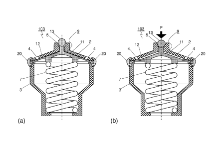
The first half shell (2) (cf. Figure 2) defines together with the membrane (9)
the first
chamber which is in fluid communication through an inlet opening (5) with the
interior of
the cartridge (10) containing the propellant gas at high pressure. The first
chamber also
comprises at least one outlet opening (4), which is in fluid communication
with the
interior of container (30), to allow propellant gas to be injected into the
container (30) at
a reduced pressure. The second half shell (3) (cf. Figure 2) defines together
with the
membrane (9) the second chamber containing means (7) for biasing the membrane
(9) to
obturate the openings (4).
The membrane (9) sealingly separates the first from the second chambers and is
sandwiched between the first and second half-shells (2, 3). It comprises a
central section
(11) resting on the means (7) for biasing the membrane and as such is sturdier
than the
peripheral section (12) concentrically surrounding it, which is flexible
enough to liberate
- 7-
CA 02784687 2012-06-15
WO 2011/073346 PCT/EP2010/069970
the passages (4) when the pressure in the first chamber is sufficient to
compress the
means (7) for resiliently biasing the membrane. The diaphragm (9) further
comprises
means (13) for obturating the inlet opening (5) when the pressure in the first
chamber is
above a given pressure limit value. Said means comprise a body having a
surface
matching a surface of said inlet opening (5). The body of the obturating means
(13) is
generally connected to the membrane itself through a central stem sufficiently
thin to
allow the free passage thereof through the inlet opening (5) such that the
membrane and
the body of the obturating means (13) are located on either side of the
opening (5), and
sufficiently long to allow a certain compression of the membrane biasing means
(7)
before the matching surfaces of the obturating means and of the opening (5)
sealingly
contact one another. With this configuration, as the pressure grows in the
first chamber,
the biasing means (7) are progressively compressed until the displacement of
the
membrane corresponds to the free length of the stem supporting the body of the
obturating means which then sealingly contact said matching surface of the
inlet opening
(5). Only when the pressure in the first chamber drops sufficiently can the
biasing means
resiliently recover some of their original geometry, thus dislodging the body
of the
obturating means from opening (5). In Figures 2 and 3 the body of the
obturating means
(13) is represented as a ball of substantially spherical shape. It is clear
that other
geometries, like a cone or similar, can be used instead.
As reviewed in the background section, the central and peripheral sections of
the
diaphragm are usually made of different materials, the former being a stiff
material and
the latter usually an elastomer. Alternatively, both sections may be made of
the same
material. According to the present invention, the diaphragm is made of a
single polymer
of the same class as the polymer constituting the first and second half shells
(2) and (3).
This configuration greatly eases recyclability and reduces the production
costs, since all
three components: first and second half shells and diaphragm, can thus be
produced and
assembled in a single injection moulding tool.
-8-
CA 02784687 2012-06-15
WO 2011/073346 PCT/EP2010/069970
The polymeric components of the valve are of the same class if they belong to
the same
polymer family and do not require separation for recycling. In particular,
several types of
polyolefins are recycled together, such as polypropylene (PP) and polyethylene
(PE), or two
different grades of the same polymer, such as PE and HDPE. Similarly different
grades of
polayamides (PA) can be combined, such as PA6, PA6.6, PA6.1 0, PA12, etc.
Other classes
of polymers suitable for the present invention are thermoplastic polyesters,
such as PET,
PEN, polystyrenes, ABS, etc. A preferred class of polymers is polyolefin, in
particular PP,
for its high properties to price ratio. Thermoset materials could be used but
their
recycling is rather limited to grinding for use as solid fillers, and as such
are less
preferred than thermoplastic materials.
The means (7) for resiliently biasing the diaphragm (9) usually consists of a
helicoidal
spring. Other means, however, can be considered within the present invention,
such as a
resilient elastomeric bloc, or a hydraulic system. The nature of the biasing
means,
however, is not essential to the present invention. Upon recycling, a metallic
helicoidal
spring can easily be separated from the polymeric components of the valve with
a
magnet, by gravimetric methods or any other method known in the art. Similarly
a
resilient elastomeric bloc can be separated by gravimetric methods, although
this is not
an optimal solution for the valve recyclability.
The two half shells (2, 3) must be joined together with the diaphragm (9)
sandwiched
therebetween to form the first and second chambers of the valve. Several
joining methods
can be used. Care must be taken to ensure gas tightness at the joining line
between the
membrane (9) and the rims of the first and second half shells (2, 3). This
requirement is
particularly sensitive when, as according to the present invention, the
diaphragm
comprises no elastomeric peripheral section, which would ensure gas tightness
between
the two chambers simply by pressing the elastomeric material between the rims
of the
half shells. In this context, welding or gluing can give a suitable joint.
Welding of
polymeric components can be achieved e.g., with high frequency vibrations,
using a
solvent, or with heat. All these techniques, however, must be performed as a
separate
-9-
CA 02784687 2012-06-15
WO 2011/073346 PCT/EP2010/069970
assembly stage, which increases the production costs. The same applies to
joining with
mechanical means, like screws or rivets, with the exception of snap fittings.
In this case,
however, the design must be such as to ensure gas tightness at the joining
line between
the shells and the diaphragm. A particularly preferred joining technique is to
over-inject
at the interface line a polymeric ribbon (20) of the same class as the other
polymeric
components of the valve. In order to strengthen the joint and to ensure gas
tightness at
the interface, the rims of the first and second shells (2, 3) and/or the
peripheral edge of
the membrane (9) advantageously have a specific structure such as grooves or
protrusions for allowing the polymeric ribbon (20) to anchor the components
together
and to sealingly embed the peripheral edge of the membrane (9). This joining
technique
is particularly preferred because it has the following advantages:
= the joint strength is particularly high;
= recyclability of the valve is made easier by the use of a single class of
polymer for
all its polymeric components, including the joining ribbon;
= gas tightness of the interface between the half shells and the diaphragm is
ensured by the polymeric ribbon embedding the peripheral edge of the
diaphragm;
= the joining operation does not require a separate assembly stage as it can
be
carried out within the same tool as the one used for the manufacture of the
half
shells (2, 3) and the diaphragm (9);
= one half shell (2, 3) of the valve can be an integral part of the chime (33)
or of the
closure (1) of the container (30), thus eliminating a further assembly step.
The pressure regulating valve of the present invention can be produced quite
economically, a particularly sensitive issue for disposable home beverage
dispensers of
small capacity of the order of a few litres. The two half shells (2, 3) can be
injection
moulded in two cavities of a same tool. Advantageously, the diaphragm (9) is
produced in
a third cavity of the same tool. The cavity containing one half shell is
shifted or rotated to
a position facing the cavity containing the second half shell. Whether
produced separately
-10-
CA 02784687 2012-06-15
WO 2011/073346 PCT/EP2010/069970
or within the same tool, the membrane (9) is inserted between the cavities
containing the
two half shells and clamped therebetween. A polymeric ribbon (20) is then
injected at the
interface between the two half shells and the membrane to form a strong
sealing joint.
Tools designs and solutions for carrying out this processing technique have
been
proposed in the literature for other applications, such as in jP77217755,
jP4331879,
EP1088640, and DE1021 1663;
-11-