Note: Descriptions are shown in the official language in which they were submitted.
CA 02784945 2012-06-19
WO 2011/076427 PCT/EP2010/007923
1
Aircraft with a control device
This application claims the benefit of the filing date of German Patent
Application
No. 10 2009 060 327.1 filed 23.12.2009 and of United States Provisional Patent
Application No. 61/289,488 filed 23.12.2009, the disclosures of which
applications are
hereby incorporated herein by reference.
The invention relates to an aircraft with a control device.
From the general state of the art, flow-influencing devices that are
integrated in the
aerofoils of an aircraft are known, by means of which flow-influencing devices
specified
local aerodynamic flow states on segments of the aerofoil are to be
stabilised. In this
arrangement it can, in particular, be provided for a reduction of turbulence
on the
aerofoil so as to prevent, in critical flight states, the local lift
coefficient from being
reduced as a result of the formation of local turbulent flow. Such flow-
influencing
devices can be implemented as:
= passive vortex generators,
= devices that provide continuous blowing-out in regions where there is a
danger of
separation,
= devices by means of which suction removal of the flow that has a tendency to
separate is achieved.
It is the object of the invention to provide measures by means of which the
aerodynamic performance of controlled aircraft can be improved.
This object is met by the characteristics of claim 1. Further embodiments are
stated in
the related subordinate claims.
According to the invention an aircraft is provided whose aerofoil comprises a
main wing
and at least one adjustable flap that is arranged so as to be adjustable
relative to the
CA 02784945 2012-06-19
WO 2011/076427 PCT/EP2010/007923
2
aforesaid. The adjustable flap can be a control flap. As an alternative or in
addition the
adjustable flap. can be a high-lift flap. The aircraft comprises:
= an actuator for operating the at least one adjustable flap or control flap,
as well as
a sensor device for acquiring the set position of the adjustable flap,
= at least one arrangement of flow-influencing devices, which extends in at
least
one surface segment of the main wing, which surface segment extends in the
direction of the wingspan, and/or of at least one control flap of each
aerofoil, for
the purpose of influencing the fluid that flows over the surface segment,
= at least one arrangement of influencing flow-state sensor devices for
measuring
the flow state at the respective segment,
= a flight control device which on the input side is functionally connected to
the
sensor device for acquiring the set position of the adjustable flap or control
flap
and to the flow-state sensor devices, which flight control device for the
purpose of
transmitting actuating commands on the output side is functionally connected
to
the actuator and the flow-influencing devices,
= a flight-state sensor device for acquiring flight states of the aircraft,
wherein the
flight-state sensor device is functionally connected to the flight control
device for
transmitting flight states, and
= a specifying device for generating desired commands, which correspond to
flight
states of the aircraft, the specifying device being functionally connected to
the
flight control device for transmitting the commands as input signals of the
flight
control device.
the flight control device in particular comprises a function that for the
purpose of
optimising local lift coefficients on the aerofoil depending on the respective
acquired
flight state carries out a selection of the flow-influencing devices that are
to be
operated. The flight control device can in particular be designed in such a
manner that
it generates actuating commands for commanding the actuator and the flow-
influencing
devices and transmits them to the aforesaid, wherein the flight control device
CA 02784945 2012-06-19
WO 2011/076427 PCT/EP2010/007923
3
determines the then current actuating commands on the basis of the desired
commands of the specifying device, the sensor signals of the flight-state
sensor device
and the sensor signals of the flow-state sensor device. The flight control
device can, in
particular, comprise a function that for the purpose of optimising local lift
coefficients on
the main wing depending on the flight state carries out a selection of the
flow-
influencing devices that are to be operated.
In this arrangement it can, in particular, be provided for the regulating
device to
determine the desired flow-state values segment by segment as local desired
flow-
state values in order to in each case control an arrangement of flow-
influencing devices
in each case in a surface segment of each wing or of a flap for influencing
the fluid
flowing over the surface segment, which surface segment extends in the
direction of
the wingspan or flap span.
The adjustable flap, which is operated by the actuator controlled by the
flight control
device, can, in particular, be a control flap of the aircraft. As an
alternative or in
addition, the adjustable flap can also be an adjustment flap. In this context
the term
"adjustment flap" refers to an adjustable flap that adjusts or sets an
operating state or a
flight state and in so doing is not, or is not primarily, used for controlling
the aircraft.
Thus the actuator movement of the control flap continuously moves during
control of
the aircraft, while the adjustment flap does not move during a flight phase or
part of a
flight phase, e.g. during takeoff or landing. The adjustment flap can, in
particular, be a
high-lift flap such as a leading edge flap or a trailing edge flap.
Furthermore, the flap
that according to the invention is controlled by the flight control device can
be a flap
that has both the function of an adjustment flap and the function of a control
flap.
The flight control device is, in particular, designed in such a manner that,
for the
purpose of controlling the aircraft, apart from generating actuating commands
for
commanding the actuator of the adjustable flap also generates actuating
commands for
controlling and operating the flow-influencing devices and transmits them to
the
aforesaid. Controlling or commanding the flow-influencing devices is thus
functionally
integrated in generating actuating commands for commanding the actuator of the
at
least one adjustable flap or control flap, and the correspondingly generated
control
CA 02784945 2012-06-19
WO 2011/076427 PCT/EP2010/007923
4
commands for operating the flow-influencing devices and the actuator of the at
least
one adjustable flap or control flap are functionally in a mutual relationship
of
dependence. In this arrangement the flight control device determines the then
current
actuating commands for controlling or commanding the actuator and actuating
commands for controlling or commanding the flow-influencing devices on the
basis of
the desired commands of the specifying device, the sensor signals of the
flight-state
sensor device and the sensor signals of the flow-state sensor device. The
specifying
device can, in particular, be a control-specifying device for operating
adjustable flaps
and in particular of control flaps for controlling the aircraft and/or for
setting adjustment
flaps according to the invention. In other words, during operation of the
control flaps
and/or of adjustment flaps the flight control device additionally carries out
optimisation
of current actual local lift coefficients by influencing the flow on the
surface of the
aerofoil and/or of the adjustable flap depending on the flight state and the
control
command by determining of a selection of respectively to be commanded flow-
influencing devices.
In this arrangement the flight control device can, in particular, comprise a
control or
regulating algorithm that corrects the aforesaid input values according to the
received
desired commands (complete control). The regulating algorithm of the flight
control
device can on the one hand comprise the synthesis of a value for lift, drag or
lift-to-drag
ratio from sensor data, in particular from sensor devices that in each case
are locally
associated with flow-influencing devices, on the aerofoil or the flap, and on
the other
hand can comprise a robust regulating algorithm for attaining a specified
target value
for the above value. The regulator is preferably supported by an anti-wind-up
reset
structure.
Selection of the flow-influencing devices to be activated at a given time, and
determination of the intensity at which the flow-influencing devices are
activated at a
given point in time can, in particular, be arrived at from a combination of
temporal
integration and a reference table, and can one-to-one be associated with a
flight-
relevant quantity, for example a key characteristic relating to the lift that
in each case is
locally associated with the flow-influencing devices. In this arrangement, in
particular, a
local lift parameter related to at least one or each segment on the flow
surface of the
CA 02784945 2012-06-19
WO 2011/076427 PCT/EP2010/007923
aerofoil or of an adjustable flap can be determined in which a plural number
of flow-
influencing devices are arranged. In this manner, for operating the flow
influencing
devices, it is indirectly possible to specify for example the lift or lift
coefficient, which
specification is subsequently by means of the algorithm converted to a
specification
relating to the numerical value. It can be further provided for the local lift
characteristic
to be used to determine the deviation of the respective local lift
characteristic from a
then current characteristic determined by an associated sensor device, by
means of
which a determination is made as to whether the respective flow-influencing
device is
activated, and if so at what intensity.
The controller or regulator can have been designed on the basis of a linear
multivariable black-box model with a method for synthesising robust
regulators. During
identification of the linear multivariable black-box model, suitable
interference signals in
the form of sudden changes in the extent of actuation are generated, and the
reaction
of the numerical measure to the aforesaid is measured. From the dynamic
behaviour of
the reaction a linear differential calibration system is obtained by means of
parameter
identification methods, which differential calibration system represents the
basis of the
regulator synthesis. Many different instances of such identification provide a
model
family from which in each case for each synthesis a representative or average
model is
selected. In regulator synthesis it is possible to use particular methods
(e.g. H,
synthesis, robustification, robust loop shaping). The arising classically-
linear control
circuit can be supported by an anti-wind-up reset structure which when there
is a
demand for a controller variable that is above the achievable controller
variable
corrects the internal states of the regulator in such a manner that an
integration
component in the regulator does not result in overshooting or locking of the
regulator.
Thus even in the case of unrealistic requirements the regulator remains
responsive,
which increases operational safety. The regulator is always adjusted to the
then current
situation, without experiencing delays caused by previous limitations of the
controller
variable.
The regulator can, in particular, be designed as an optimum regulator that
receives all
the necessary input variables as regulating variables, and according to a
regulating
method algorithm in a matrix-like process generates the various output signals
for the
CA 02784945 2012-06-19
WO 2011/076427 PCT/EP2010/007923
6
flow-influencing device and/ or the actuator or flap drive of the at least one
controlled
adjustable flap, on the basis of calibrations and parameters derived therefrom
for the
allocation of regulating variables and controller variables depending on
flight state
variables.
According to a preferred exemplary embodiment of the invention, the regulator
is
functionally designed in such a manner that by means of an integrated
regulator
function and in particular in an operational interval or iteration step said
regulator
determines a control signal vector that includes on the one hand control
signals for the
at least one actuator of the adjustable flap, and in particular of the at
least one control
flap, and on the other hand control signals for flow-influencing devices. The
control
signals for flow-influencing devices also comprise a determination as to
whether control
signals for some or for all flow-influencing devices are to be provided at
all, i.e. as to
which flow-influencing devices are to be controlled in a given case.
According to the invention it can be provided for the flight control device to
be designed
in such a manner that by means of a model for the aircraft, which can be a
filter or
controller, it generates current control signals or a current control-signal
vector with
controller variables for commanding the actuator of the at least one control
flap and of
the flow-influencing devices and transmits said control signal vector to the
aforesaid,
wherein the flight control device determines the then current control signals
or the
current input signal vector on the basis of the desired commands of the
specifying
device, the sensor signals of the flight-state sensor device and the sensor
signals of
the flow-state sensor device.
As a result of the invention, systemic limitations relating to the maximum
movement of
the trailing edge device are taken into account, taking into account loads,
maintenance
requirements and costs, and in so doing the aerodynamic performance of a high-
lift
system is improved. Furthermore, in a more curved profile, separation of the
flow at the
top of the adjustment flap is prevented. Moreover, the invention meets the
very
stringent requirements relating to the precise setting of an adjustment flap
relative to
the main wing relating to weight and an efficient integration in the overall
system, and
CA 02784945 2012-06-19
WO 2011/076427 PCT/EP2010/007923
7
consequently an overall high-lift system can be optimised both in terms of
weight and
cost.
According to the invention, the adjustment flap can thus, in particular, be a
high-lift flap
arranged on the aerofoil of the aircraft, wherein the arrangement (15) of flow-
influencing devices and of flow-state sensor devices is arranged on the high-
lift flap
and/or on the main wing.
Furthermore, the flight-relevant characteristic provided in each case in
relation to the
flow-influencing devices can, for example, correspond to a local lift
coefficient, a local
drag, a local lift-to-drag ratio, and can be determined in a non-stationary
manner from
substitute regulating variables so that this characteristic is then used for a
desired
value comparison, and so as to finally in this manner set principally any
value, within
the framework of physics, from which value the control signals for the local
flow-
influencing devices are determined by means of linear, robust regulating
algorithms
designed for a linear model.
In this arrangement, as a result of doing away with heavy movable components,
the
regulating system is significantly faster when compared to systems based on
conventional mechanical solutions so that local flow phenomena can be
suppressed or
used in a targeted manner.
In this arrangement the function for determining the selection of the flow-
influencing
devices that are to be activated can be a filter function or can be based on a
filter
function. In particular, in this arrangement it can be provided for those flow-
influencing
devices whose respectively associated sensor devices produce measuring signals
that
are within a permissible range not to be activated, in other words are
allocated control
signals with a value of zero. In particular, in this arrangement it can be
provided for the
local flow speed or the local pressure to exceed a minimum value. In contrast
to this,
control signals for these flow-influencing devices are determined with a value
for their
activation, whose respectively associated sensor devices produce measuring
signals
that are outside a permissible range, which range can, in particular, be
defined in such
a manner that its limit forms the transition to instances of local flow
separation.
CA 02784945 2012-06-19
WO 2011/076427 PCT/EP2010/007923
8
These flow control measures individually are measures that are suitable per se
to partly
or fully prevent separation on the flap in relation to a defined region.
However, they
only represent individual sub-systemic solutions because they are designed
only for a
specific configuration.
As a result of an excitation system that is cascaded in the direction of
profile depth and
that is controlled in a segmented manner, various flow situations where there
is a
danger of separation, caused by different configurations, can be prevented
more
efficiently. Periodic or pulsed blowing-out of compressed air through slits or
similarly
designed topologies on the trailing edge flaps has already proven to be very
effective
and, in the context of the configurations investigated, has also been very
much more
efficient (by a factor of 2 to 4) in relation to the air mass flow used when
compared to
continuous blowing-out. Since the flow conditions in the region of the flap
vary as the
flap positions vary, it is also possible for different separation states with
different
separation positions to occur at the trailing edge flap.
However, an actuator system with a determined excitation position is only
optimised in
relation to a particular range so that in the off-design case the
effectiveness of the
active flow control is reduced, and the energy requirement can increase
excessively.
Periodic or pulsed blowing-out through slits or similarly designed topologies
at the
trailing edge flap with segmented and cascade-like arranged slits or similarly
designed
topologies can therefore prove to be particularly efficient because the
respective flow
states can be better controlled, and as a result of the pulsed nozzle flow the
energy
input takes place in a targeted and efficiently distributed manner into the
flap flow that
has separated or that is in the process of separating. If, moreover,
regulation of the lift
coefficient is used as an exemplary target parameter, the effect can be
controlled
autonomously and designed efficiently.
Initial experimental results on two-dimensional profiles show that a cascade-
like
arrangement of the excitation system can efficiently cause the flow that tends
towards
separation to reattach. Investigations on industrial wind tunnel models have
already
proven the effect of this flow control technique on the basis of model
actuators.
CA 02784945 2012-06-19
WO 2011/076427 PCT/EP2010/007923
9
A necessary number of suitable sensors, for example pressure sensors, are
integrated,
in profile depth direction and in wingspan direction, in the trailing edge for
the purpose
of detecting the then current local flow state. The measuring data obtained in
this
manner and the target value, specified by the pilot, of a particular
parameter, for
example of the lift coefficient, the sink rate and/or the climb rate, are used
as input
values for a correspondingly designed regulating loop. The parameters of
frequency,
pulse width, pulse entry into the flow, and/or the phase offset between the
excitation
positions can be used as controller variables for the actuator system.
Depending on the
then current flow case, the excitation positions can be operated separately or
jointly.
Segmented pulsed compressed-air actuators are particularly suitable as an
excitation
mechanism, because they have already proven themselves in numerous
experiments.
However, in principle, other actuators, for example synthetic jet actuators or
mechanically, electrically and/or pneumatically driven actuators, can also be
used for
the application described herein, provided they comprise a corresponding
function and
performance, and furthermore meet the requirements for integration in a
control circuit
for dynamic control / regulation.
According to a further aspect of the invention, it can be provided for the
flight control
device to comprise a flight-state controlling device or flight-state
regulating device and
a flow-state controlling device or flow-state regulating device, wherein:
= the flight-state controlling device is designed in such a manner that on the
basis
of the desired commands of the specifying device, the sensor signals of the
flight-
state sensor device and on the basis of sensor signals of the flow-state
sensor
device it generates desired commands to the actuator of the control flap and
of
desired flow-state values to the flow-influencing devices, and
= the flow-state controlling device is functionally connected to the flight-
state
controlling device for receiving the desired flow-state values for commanding
the
flow-influencing devices, and is designed in such a manner that the flow-state
controlling device, on the basis of the desired flow-state values and on the
basis
of the sensor signals of the flow-state sensor device of the flow-influencing
devices, transmits flow-state actuating commands to the flow-influencing
devices.
CA 02784945 2012-06-19
WO 2011/076427 PCT/EP2010/007923
The desired flow-state values can, in particular, be the local lift
coefficients or the ratios
of drag coefficient to lift coefficient in that segment.
Furthermore, the flight control device can comprise a control function that
receives as
input signals the actuating commands to the actuator of the control flap, and
the flow-
state actuating commands to the flow-influencing devices, on the basis of a
correlation
function co-ordinates these, and generates actuating commands for actuating
the
actuator of the control flap and of the flow-influencing devices, and
transmits them to
the aforesaid. In this arrangement the control function can be carried out in
such a
manner that optimisation of the actuating commands to the flow-influencing
device and
of the actuating commands to the actuator of the control flap takes place,
taking into
account the output available at the then current time and/or the dynamics of
the flow-
influencing device and/or of the actuator of the control flap.
According to the invention the flow-influencing device of a main wing or of
the
adjustment flap can comprise a pressure chamber, arranged in the main wing
and/or in
the adjustment flap, for receiving compressed air; an outlet chamber with
outlet
openings; one or several connecting lines for connecting the pressure chamber
to the
outlet chamber; at least one valve device integrated in the connecting line,
which valve
device functionally communicates with the flight control device, wherein the
flight
control device controls the valve device by means of the then current control
signal
vector in order to let compressed air present in the pressure chamber either
not flow or
flow at a corresponding speed and/or throughput through the outlet openings
according
to the actuating values of the then current control signal vector in order to
influence the
flow around the surface of the main wing or of the adjustment flap.
According to the invention the flow-influencing specifying device can comprise
a control
input device by means of whose activation the desired commands are generated,
or
can comprise an autopilot device which on the basis of a specified operating
mode
generates the desired commands, e.g. for controlling the path of the aircraft
on a
specified desired path.
In this arrangement the aircraft according to the invention can be designed in
such a
manner that the flight control device is designed as a flight-state regulating
device or
CA 02784945 2012-06-19
WO 2011/076427 PCT/EP2010/007923
11
that it comprises such a flight-state regulating device as well as a flow-
state regulating
device. The flight-state regulating device is designed in such a manner that,
on the
basis of the desired commands of the flow-influencing specifying device and
the sensor
signals of the flight-state sensor device, it transmits input signals to the
flow-state
regulating device that is functionally connected to the flight control device.
Furthermore,
in this arrangement the flow-state regulating device can be designed in such a
manner
that, on the basis of the input signals of the flight-state regulating device
and on the
basis of the sensor signals of the flow-state sensor device of each segment,
it
generates flow-state actuating commands for controlling the flow-influencing
device of
each segment and transmits them to the flow-influencing device of each segment
in
order to control the aircraft according to the desired commands of the flow-
influencing
specifying device.
In this arrangement it can be provided for the flight-state regulating device
to comprise
a segment control function that is designed in such a manner that it generates
actuating commands to the flow-influencing device of each segment and/or the
actuating commands to the actuator on the basis of the control signals of the
flight-
state regulating device by optimisation, taking into account the output and/or
dynamics,
available at the then current point in time, of the flow-influencing device
and/or of the
actuator of the adjustable flap.
According to the invention it can be provided for the arrangement of flow-
influencing
devices to comprise blow-out openings that are arranged in one segment or in
several
segments, and to comprise a flow generating device, arranged in the wing, for
blowing
out and/or removing by suction, by means of which flow generating device fluid
is
blown out of, or removed by suction from, the blow-out openings in order to
influence
the lift coefficient that locally occurs at the segment.
It can further be provided for the arrangement of flow influencing devices to
additionally
comprise suction openings that are arranged in one segment or several
segments, and
to comprise a suction device that is arranged in the wing and is in fluidic
connection
with the suction openings, through which suction device fluid from the suction
openings
is sucked in, in order to influence the lift coefficient that locally occurs
at the segment.
CA 02784945 2012-06-19
WO 2011/076427 PCT/EP2010/007923
12
Flow control can take place by means of blowing-out pulsed compressed air
across the
span at a defined profile depth position of the adjustment flap or of the
trailing edge
flap. The valve device or switching unit provided according to one embodiment
of the
invention can be operated at variable frequency, variable duty cycle (ratio of
time with
through-flowing air to the duration of a pulse) and air mass flow so that a
(periodically)
pulsed airflow with a variable pulse is generated. By means of a pressure
chamber or
an actuator chamber the desired outlet speed distribution can be generated at
the
place of excitation.
On the basis of the load conditions and safety conditions relating to weight
limits in the
takeoff and landing phases, technical boundaries for the design of such a
trailing edge
flap without and with a lowered spoiler and extended trailing edge flap are
significantly
expanded.
According to the invention, the at least one segment can comprise several
segments
that are arranged one behind the other when viewed in the wingspan direction
of the
wing.
The specifying device for generating desired commands that correspond to
flight states
of the aircraft as input signals of the flight control device can be a control
input device
for controlling the aircraft, and the input signals can be variables relating
to the climbing
rates or sinking rates or to acceleration. The specifying device can comprise
a control
input device by means of whose activation the desired commands are generated.
Furthermore, the specifying device can comprise an autopilot device, which, on
the
basis of a specified operating mode generates the desired commands, e.g. for
controlling the path of the aircraft on a specified desired track.
The arrangement of flow-influencing devices can also be designed so as to be
switchable by the pilot.
Below, the invention is described with reference to the enclosed figures which
show the
following:
CA 02784945 2012-06-19
WO 2011/076427 PCT/EP2010/007923
13
= Figure 1 a perspective view of an aircraft in which the flow-influencing
device
provided according to the invention is integrated;
= Figure 2 a diagrammatic view of the cross section of an aerofoil with an
arrangement, according to the invention provided in at least one segment of
the
aforesaid, of flow-influencing devices and of flow-state sensors as well as an
optionally provided adjustable flap that can be adjusted by an adjustment
device
with an actuator;
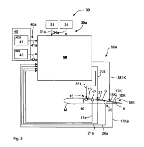
0 Figure 3 an exemplary embodiment of a flight controlling device, provided
according to the invention, with a flight control device which, for example,
is
functionally connected to an actuator of a control flap and with two flow-
influencing devices in each case of an arrangement distributed over a surface
segment of a flow-influencing device and a flow-state sensor device, wherein
the
flow-state sensor device of each segment is functionally connected to the
flight
control device, and wherein in each case an arrangement distributed over a
surface segment of a flow-influencing device and a flow-state sensor device is
arranged at the top of the main wing and at the top of an adjustment flap,
= Figure 4 a section view of an exemplary embodiment of the flow-influencing
device that is provided according to the invention, which flow-influencing
device
is, for example, installed in an adjustment flap,
= Figure 5 a perspective diagrammatic view of the flow-influencing device
shown in
Figure 4,
= Figure 6 a diagrammatic view of a wing with a main wing and an adjustment
flap
coupled thereto, in the form of a high-lift flap, at the top of which an
arrangement,
provided according to the invention, of blow-out openings of a flow-
influencing
device is arranged,
= Figure 7 a top view of a surface segment of an adjustment flap with an
arrangement, implemented as an example, of flow-influencing devices and flow-
state sensor devices.
CA 02784945 2012-06-19
WO 2011/076427 PCT/EP2010/007923
14
In the figures, components and functions with an identical or similar function
have the
same reference characters.
The exemplary embodiment, shown as an example in Figure 1, of a controlled
aircraft
F to which the invention can be applied, according to the commonly-used shape
comprises two aerofoils 1 a, 1 b, each comprising at least one aileron 5a or
5b.
Furthermore, the aircraft shown in Figure 1 on each aerofoil 1a, 1b comprises
three
leading-edge lift bodies 3a, 3b and three trailing-edge lift bodies 4a, 4b as
high-lift
flaps. Optionally, the aerofoils 1 a, 1 b can each comprise a plural number of
spoilers 2a,
2b. Furthermore, the aircraft F comprises a tail unit H with a vertical
stabiliser 8 with a
rudder 9 and a horizontal tail 6, in each case with at least one elevator
control surface
7. The horizontal tail 6 can, for example, be designed as a T-tail, as shown
in Figure 1,
or as a cruciform tail.
In Figure 1 a co-ordinate system KS-F related to the aircraft F is entered,
comprising
an aircraft longitudinal axis X-F, an aircraft transverse axis Y-F and an
aircraft vertical
axis Z-F. An aerofoil co-ordinate system KS-T with an axis S-T for the
wingspan
direction, an axis T-T for the depth direction and an axis D-T for the
thickness direction
of the aerofoil can be associated with each aerofoil 1 a, 1 b (Figure 2).
Furthermore, a
flap co-ordinate system KS-K with an axis S-K for the wingspan direction of
the flap, an
axis T-K for the depth direction and an axis D-K for the thickness direction
of the flap
can be associated with each flap (Figure 2).
Figure 2 diagrammatically shows an aerofoil 1 comprising a main wing M and a
control
flap S, which is provided for controlling or manoeuvring the aircraft, as well
as a high-lift
flap K. In Figure 2 the control flap S is shown as a spoiler, however, from
the functional
point of view according to the invention it could alternatively or
additionally, for
example, be an aileron or, if it is not arranged on the main wing, an elevator
control
surface 7 and/or rudder 9.
Figure 2 shows in detail a main wing 10 with an adjustable flap K which is
coupled to
the main wing M. According to the invention, the aerodynamic body can be the
adjustable flap K, in other words an aerodynamic body that is adjustably
arranged on
the aircraft and thus, for example an adjustable flap shown in Figure 1, in
other words
CA 02784945 2012-06-19
WO 2011/076427 PCT/EP2010/007923
for example a high-lift flap, an aileron, a spoiler, an elevator control
surface or a rudder.
The aerodynamic body provided according to the invention can, in particular,
also be a
main wing M. The main wing M at its top M-1 extending on the suction side A
comprises a bottom M-2, which extends on the pressure side B of the aforesaid,
and
possibly a rear face, which faces the high-lift flap K. For the high-lift flap
or generally for
the adjustable flap K or the aerodynamic body a flap depth direction T-K or
generally a
depth direction, a wingspan direction S-K or generally a wingspan direction,
and a flap
thickness direction D-K or generally a flap thickness direction has been
defined. The
adjustable flap K or high-lift flap comprises a top K1 that extends on the
suction side A
of the high-lift flap K, and a bottom K2 that extends on the pressure side B
of the high-
lift flap K.
For further explanation of the invention, reference is made to the
combination,
diagrammatically shown in Figure 2, of a main wing, at least one spoiler as a
control
flap and a high-lift flap as an adjustment flap. In this application the at
least one control
flap can, in particular, additionally comprise an aileron and/or the rudder.
As an
alternative or in addition to the high-lift flap as an adjustment flap the
horizontal
stabiliser and/or the vertical stabiliser and generally also an adjustment
flap and
generally an adjustable flap of the aircraft can be functionally included
according to the
invention.
According to the invention, a flight control device 50 is provided that is
designed in
such a manner that it generates actuating commands for commanding the
respective
actuator 21 of a control flap S and/or the respective actuator 20 of an
adjustable flap K
such as the high-lift flap and of flow-influencing devices 15; 15K arranged on
the
aerofoil 1 a, 1 b, 1 and or on at least one adjustment flap, and transmits
them to the
aforesaid (Figure 3). The flight control device 50 determines the then current
actuating
commands 50a on the basis of the desired commands 30a of the specifying device
30,
the sensor signals 40a of the flight-state sensor device 40 and the sensor
signals 17a,
17Ka of the flow-state sensor device 17 and 17K, respectively, and optionally
the
sensor signals of a sensor for acquiring the state of the control flap S
and/or of the
adjustable flap K. The state of the control flap S and/or the flap K can be
one or more
of the following parameters of the control flap S and the flap K,
respectively: the
CA 02784945 2012-06-19
WO 2011/076427 PCT/EP2010/007923
16
position, the velocity, the acceleration and/or another state. The desired
commands
30a as input signals of the flight control device 50 can comprise a desired
acceleration
and/or a desired direction of the aircraft. The flight control device 50 is
designed in
such a manner that it generates a then current input signal vector 50a for
commanding
the actuator 21 and the flow-influencing devices 15; 15K and transmits it to
the
aforesaid.
The flow-influencing devices 15; 15K, which are commanded by the flight
control
device 50 by means of the then current input signal vector 50a, can be
arranged on the
main wing M and/or on an adjustment flap K, wherein the flow-influencing
device 15;
15K in each case of a surface segment comprises at least one flow-influencing
device
and at least one flow-state sensor. According to Figure 2, in a segment 10 at
the top M-
1 of the main wing and at a segment 10K at the top K1 of the adjustment flap K
in each
case an arrangement 15 or 15K comprising at least one flow-influencing device
16 or
16K and at least one flow-state sensor 17 or 17K is arranged. In Figure 1 at
the main
wings of the aerofoils corresponding segments 11 a, 11 b, 12a, 12b are
diagrammatically entered, in which in each case such an arrangement 15
comprising at
least one flow-influencing device 16 and at least one flow-state sensor 17 is
arranged.
As shown in Figure 2, as an alternative or in addition such a segment 10K
comprising
an arrangement 15K of at least one flow-influencing device 16K and at least
one flow-
state sensor device 17K can be arranged at the top K1 or at the bottom K2 of
the
respective adjustment flap K.
The flow-influencing device 15 or 15K is designed in such a manner that by
means of
it, on the basis of then current control signals or on the basis of a then
current control
signal vector 50a, the flow present at the respective surface, and thus the
lift coefficient
of the main wing M or of the adjustable flap K, can be influenced. In this
arrangement
the flight control device 50 comprises a function which for the purpose of
local lift
coefficients on the aerofoil makes a selection, depending on the flight state,
of the flow-
influencing devices 15; 15K that are to be operated. In this arrangement the
flight
control device determines desired local flow-state values segment by segment;
in other
words the then current control signal vector 50a comprises control signals for
each of
the controllable segments 10, 10K.
CA 02784945 2012-06-19
WO 2011/076427 PCT/EP2010/007923
17
In this arrangement the control signal vector 50a can be such that it
comprises a value
for all the flow-influencing devices 15; 15K that can be operated, wherein the
flow-
influencing devices 15; 15K, which on the basis of the selection and according
to the
respective then current control signals or then current control signal vector
50a are not
to be operated, receive a setting value of zero.
In this arrangement the flight control device 50 can, in particular, be
designed in such a
manner that by means of a regulator model for the aircraft it generates then
current
control signals or a then current control signal vector 50a for commanding the
actuator
21 of the at least one control flap S and of the flow-influencing devices 15;
15K and
transmits them to the aforesaid, wherein the flight control device 50
determines the
then current control signals or the then current input signal vector 50a on
the basis of
the desired commands 30a of the specifying device 30, the sensor signals 40a
of the
flight-state sensor device 40, and the sensor signals of the flow-state sensor
device 17;
17K.
Figure 4 shows an exemplary embodiment of the flow-influencing device 16, 16K,
provided according to the invention, of a segment, with the example showing a
flow-
influencing device 16K of an adjustment flap K. In this arrangement the flow-
influencing
device 16K comprises a pressure chamber 101 to receive compressed air, an
outlet
chamber or blow-out chamber 103 and one or several connecting lines 105 for
connecting the pressure chamber 101 to the outlet chamber 103. The blow-out
chamber 103 comprises at least one outlet opening or blow-out opening and
preferably
an arrangement 110 of outlet openings or blow-out openings. Purely for
illustration
Figure 5 shows a single blow-out opening 104. At least one valve device 107 is
integrated in the at least one connecting line 105, which valve device 107 is
functionally
connected to the flight control device 50. The flight control device 50
controls the valve
device 107 by means of the control signal vector 50a that is current at the
time, in order
to let compressed air present in the pressure chamber 101, corresponding to
the
setting values of the then current control signal vector 78, either not flow
or flow at a
corresponding speed and/or throughput into the outlet chamber 103, from which
location the air exits through an arrangement 110 of blow-out openings in
order to
influence the flow around the surface K1 of the adjustment flap K.
CA 02784945 2012-06-19
WO 2011/076427 PCT/EP2010/007923
18
Introducing compressed air into the pressure chamber 101 can take place in
various
ways. In this arrangement it can be provided for the compressed air to be
taken from
the outer flow in a stagnation point region at the surface of a aerodynamic
body of the
aircraft, and in particular in a stagnation point at the adjustment flap or in
a stagnation
point at the main wing. It is also possible for a pressure generating device
or a pump or
a flow variator to be connected to the pressure chamber, with said pressure
generating
device or pump taking up air by way of a supply line. The supply line can, in
particular,
emanate from an opening or an arrangement of openings at the top of the main
wing M
and/or of the flap K. In this arrangement said opening can be arranged in one
location,
or said arrangement of openings can be arranged so as to be distributed over a
region
of the main wing M and/or of the flap K, which region is provided in such a
manner that
at these positions suction removal effects occur that correlate in a
predetermined
manner with the blow-out effects generated at the arrangement 110 of blow-out
openings.
The flow-influencing device 16K, which in Figure 4 is shown in its installed
state, is
diagrammatically shown in Figure 5 as a structurally isolated device. Figure 6
diagrammatically shows an aerofoil with a main wing M and an adjustment flap
K,
coupled thereto, in the form of a high-lift flap, at the top of which an
arrangement 110 of
blow-out openings provided according to the invention is arranged.
The arrangement 110 of blow-out openings or the opening device preferably
comprises
an arrangement of, in particular, slit-shaped openings (Figures 5 to 7).
According to the
invention it is preferably provided for the blow-out openings that fluidically
are
communicating with one or several blow-out chambers to be distributed over a
surface
segment of the flow body of the aircraft. In this arrangement, several surface
segments
can be arranged side by side or one behind the other when viewed in the
direction of
flow S in order to influence the flow over a larger region of the flow body.
The flight
control device 50 determines the actuating commands and corresponding setting
values for each arrangement 15, 15K of flow-influencing devices 16 or 16K and
flow-
state sensor devices 17 or 17K of each controllable segment 10, 10K of
segments 10,
10K that are distributed over the flow body, in other words for example over
the main
CA 02784945 2012-06-19
WO 2011/076427 PCT/EP2010/007923
19
wing, at least one adjustment flap and/or control flap, with such arrangements
15, 15K
of flow-influencing devices 16 or 16K and flow-state sensor devices 17 or 17K.
Figure 8 shows, as an example, a top view of a surface segment 10K with an
arrangement 15K of flow-influencing devices and flow-state sensor devices as
they
can, according to the invention, generally be arranged in a surface segment of
the main
wing or of an adjustment flap and generally of a flow body of the aircraft F.
The
arrangement shown in Figure 7 comprises an arrangement 110 of blow-out
openings
104 that are distributed in a matrix-like manner over the surface segment 10K.
Generally speaking, the blow-out openings 104 of the arrangement 110 of outlet
openings are distributed over the respective surface segment in order to
influence the
flow around or above the entire region of the surface segment 10 or 10K.
Preferably, a
pressure chamber and a valve device 107 is associated with the openings 104 of
a
surface segment 10, 10K. As an alternative it can also be provided for a
pressure
chamber 101 to be associated with several surface segments 10, 10K.
The blow-out openings 104 comprise a shape which is optimal for influencing
the flow
around the respective surface segment 10, 10K. In this arrangement it can be
provided
for various forms of blow-out openings 104 to be used within a surface segment
10,
10K. For example, the blow-out openings 104 can also be designed in an
ellipsoid or
crescent shape.
Furthermore, within a surface segment a plural number of flow-state sensor
devices 17
or 17K are arranged, which in Figure 8 are diagrammatically shown as circular
icons.
All the flow-state sensor devices 17 or 17K are functionally coupled to the
flight control
device 50 (Figure 3) for transmitting current flow states at the position of
the respective
flow-state sensor device 17 or 17K in the form of the sensor signals in each
case
generated by each flow-state sensor device 17 or 17K. On the basis of the
measured
flow states, in the flight control device 50 a determination is made in
relation to each
segment, at which blow-out openings 104 air is to be blown out and at what
intensity, in
order to adjust a flight state for the aircraft, which flight state
corresponds to the desired
commands generated by the specifying device 30 for generating flight states of
the
CA 02784945 2012-06-19
WO 2011/076427 PCT/EP2010/007923
aircraft. In this arrangement the flight control device 50 at the same time
determines
desired commands for the actuator drive of the control surfaces S.
Various surface segments can be arranged on the surface of the flow body, in
other
words for example of the main wing and/or of the adjustment flap K, either
side by side
or overlapping each other.
Furthermore, it can be provided for the flight control device 50 to use flow
states that
are determined by means of flow-state sensor devices 17, 17K which are
arranged in
further surface segments 10, 10K for determining actuating commands of flow-
influencing devices 16, 16K.
On the basis of the corresponding function of the flight control device 50 the
latter, by
commanding the flow-influencing devices 16 or 16K of one or several surface
segments 10, 10K in particular also sets the extent to which the flow present
on the
respective surface segment 10, 10K can be influenced. To this effect,
corresponding
values of the then current control signal vector 70a are determined. In this
arrangement
the flight control device 50 controls the valve device or devices 107 of
several surface
segments 10, 10K. In this arrangement, in particular, pulsed blowing-out can
be
provided for.
As an alternative or in addition, it can be provided for the flight control
device 50 to
control an opening device on the respective blow-out openings 104 in order to,
by
opening and closing the aforesaid, set the blow-out flow at the respective
blow-out
opening 104.
In addition it can be provided for the flight control device 50 to be
functionally coupled
to a pressure generating device or flow assistance drive (not shown), which is
coupled
to the pressure chamber, in order to, by means of corresponding control or
commanding of the pressure generating device or flow assistance drive,
respectively,
to set the pressure in the pressure chamber and in this manner to set the blow-
out
speed at the openings 104 of a surface segment 10, 10K. In this arrangement it
can, in
particular, be provided for the pressure in the pressure chamber to be set on
the basis
of the flight state and in particular on the basis of the flight speeds and
the flight altitude
CA 02784945 2012-06-19
WO 2011/076427 PCT/EP2010/007923
21
or variables derived therefrom. Furthermore, it can be provided for the flight
control
device 50 in particular flight state regions, for example during cruising, to
deactivate the
pressure generating device. Generally speaking, the pressure generating device
can
also operate at a fixed, set performance, or said pressure generating device
can be
designed in such a manner that with it, based on corresponding control by
means of a
control function, the inlet pressure and/or the blow-out pressure and/or the
differential
pressure are varied or controlled.
In this arrangement the flow assistance drive can be installed or integrated
in a channel
connected to the opening.
The flow-state sensor devices 17, 17K can generally be designed from a sensor
for
acquiring the characteristics of the flow state at the top of the main wing M
or of the flap
K, which sensor is designed in such a manner that by means of the signal
generated
by the sensor the flow state can unequivocally be determined, in other words
it can be
determined whether an attached or detached flow is present.
The invention provides for an aircraft with a flight controlling device with
an actuating
device or control input device 31, connected to the flight control device, for
generating
desired control commands 31 a for controlling the aircraft F. The control
input device 31
of the aircraft F usually comprises a control input device 31, arranged in the
cockpit of
the aircraft, for entering control inputs for controlling the flight path of
the aircraft, which
control input device 31 can, in particular, comprise the pilot input means
such as a
joystick and optionally also pedals.
Furthermore, the flight controlling device can comprise an operating-mode
input device
and/or an autopilot 34, which generates desired autopilot commands 34a for
controlling
the aircraft F, and which functionally communicates with the flight control
device 50 in
order to send the desired commands 31 a or 34a to said flight control device
50.
At least one actuator drive and/or a drive device are/is associated with the
control flaps,
for example the ailerons 5a, 5b, the spoilers 2a or 2b, that in each case are
present on
the aircraft, which actuator drive and/or drive device in each case according
to the
invention are/is optionally controlled by the flight controlling device 50 by
means of
CA 02784945 2012-06-19
WO 2011/076427 PCT/EP2010/007923
22
command signals that are desired commands, in order to adjust the respectively
associated control flaps for controlling the aircraft F. In this arrangement
it can be
provided for one of these control flaps, that this flap can be adjusted by
means of the
operation of an actuator drive, or, in order to increase failsafe operation of
the aircraft
system, by means of the operation of a plural number of actuator drives.
On the basis of desired control commands 31 a of the control input device 31
and/or the
desired autopilot commands 34a of the autopilot 34, in the flight control
device 50
desired commands are generated for operating or moving actuator drives of the
control
flaps S, 2a, 2b, 5a, 5b, and in particular the actuator for adjusting the flow-
influencing
devices 16, 16K and/or the actuator or the flap drive of the adjustment flaps
K to be
controlled, and are sent to the aforesaid. The actuator for adjusting the flow-
influencing
devices 16, 16K can, in particular, be the associated valve device and/or the
respectively associated pressure generating device or the associated flow
assistance
drive.
The aircraft F further comprises a flight-state sensor device 40, which is
functionally
connected to the flight control device 50, comprising an air-data sensor
device 41 or air
data system (ADS), for the acquisition of flight states for determining the
flight state, as
well as a flight-position sensor device or an inertial sensor device 42 or
inertial
measurement unit (IMU) for acquiring a flight state of the aircraft F and in
particular the
rotation rates of the aircraft F. The air-data sensor device 41 comprises air
data
sensors for determining the flight state of the aircraft F and in particular
the dynamic
pressure, the static pressure and the temperature of the air flowing around
the aircraft
F. By means of the flight-position sensor device 42, in particular rotation
rates of the
aircraft F, including the yaw rates and the roll rates of the aircraft, are
acquired in order
to determine the flight position of said aircraft. The flight controlling
device 50 receives
the flight-state sensor signals 40a of the sensor values acquired by the
flight-state
sensor device 40, and in particular of the air-data sensor signals 41 a of the
air-data
sensor device 41 and the flight-position sensor data 42a from the flight-
position sensor
device 42.
CA 02784945 2012-06-19
WO 2011/076427 PCT/EP2010/007923
23
The flight controlling device 50 in the form of a flight-state regulating
device 70 (Figure
3) comprises a control function which from the control input device 30
receives control
commands and from the sensor device 40 receives sensor values 40a. The control
function is designed in such a manner that depending on the control commands
30a
and the acquired and received sensor values 40a it generates actuating
commands for
the actuator drives and transmits them to the aforesaid so that, by actuating
the
actuator drives, control of the aircraft F according to the control commands
takes place.
As described, Figure 3 shows an embodiment of the invention in which on the
main
wing M and the adjustable flap K at one position in the respective wingspan
direction in
each case an arrangement 15 or 15K of flow-influencing devices 16 or 16K and
of flow-
state sensors 17 or 17K is arranged.
During flight, by means of an actuating device 31 the pilot generates a
desired
command 31 a for controlling the aircraft. The desired command 31 a for
controlling the
aircraft can, for example, be a three-dimensional acceleration vector for the
relative
change of the flight state of the aircraft, or it can be specifications
relating to a change
in direction. Furthermore, the desired-command vector can be a composition of
both
specified values and in this arrangement, for example, can generate
specifications
relating to a change in direction for lateral movement, and acceleration
specifications
relating to the vertical movement of the aircraft. In addition it can be
provided for the
desired command or desired-command vectors 34a to be generated by means of an
autopilot 34.
As shown in Figure 3, according to the invention the flow-influencing
specifying device
30 controls the flight control device 50, which subsequently on the basis of
sensor
values generates actuating commands or control signals, in particular in form
of a
signal vector or at least one respective signal vector 50a, in particular in
the form of a
control signal vector 50a an transmits the commands at least to one such
actuator
drive, which in one segment 10 or 10K on a surface of the aerofoil, and
optionally as an
alternative or in addition, is arranged on any existing at least one
adjustment flap K that
can be controlled by the aforesaid, and controls an actuator drive 21 of the
control flaps
S. On the basis of desired commands 30a of the specifying device 30, in other
words
flow-state actuating commands 351 or 351 K for operating or moving at least
one
CA 02784945 2012-06-19
WO 2011/076427 PCT/EP2010/007923
24
actuator or actuator drive of the flow-influencing device 15 or 15K of each
affected
segment 10 or 10K for adjusting the flow-influencing devices and also
actuating
commands 352 for actuating or moving at least one actuator or the flap drive
21 of the
control flaps 21 to be controlled are generated by the flight control device
50 and are
transmitted to the aforesaid.
Furthermore, it can be provided for the flight control device 50, on the basis
of
corresponding inputs to the specifying device 31 and desired commands 31 a
generated therefrom, to generate actuating commands (not shown) for adjusting
the
adjustment flap K and to transmit them to an actuator drive for adjusting the
aforesaid.
Furthermore, it can be provided for the flight control device 50 to generate
such
actuating commands for adjusting the adjustment flap K on the basis of flight
state
data. In this arrangement it can, furthermore, be provided for the flow-state
actuating
commands 351 or 351 K to be determined depending on the actuating commands for
adjusting the adjustment flap K as well as depending on the actuating commands
352
for adjusting the control flap S. As an alternative, in the then current
control signals or
current control signal vector 50a generated in each case by the flight control
device 50,
the actuating commands for commanding the actuator 21 of the at least one
control
flap S and of the flow-influencing devices 16; 16K and optionally of the
adjustment flaps
K and the information as to which one of the flow influencing devices are to
be
operated at a particular point in time are contained.
By operating or moving the actuator drives of the flow-influencing devices, in
a
predetermined manner the local lift coefficients or the ratios of drag
coefficient to lift
coefficient in that wingspan region are altered in which the segment 10 or 10K
with the
respectively controlled flow-influencing device is situated. In the case of
the presence
of several segments 10, 10K arranged in the wingspan direction and/or in the
depth
direction of the main wing or of the flap K, it can be provided for the flow-
state actuating
commands 351 or 351 K to be calibrated with and consolidated with the flow-
influencing
devices of the respective segments by means of a segment control function, or
in each
case a higher-level actuating command.
CA 02784945 2012-06-19
WO 2011/076427 PCT/EP2010/007923
For example, in the case in which each aerofoil 1 a, 1 b comprises two
segments 10,
each comprising an arrangement 15 or 15K of flow-influencing devices 16 or 16K
and
of flow-state sensors 22 or 22K and two adjustable flaps K that in a
functionally
predetermined manner are provided for stabilising and/or controlling the
aircraft, and/or
setting a flight operation mode, the flow-influencing specifying device 30 and
consequently the flight control device 50, on the basis of the control
algorithms and
regulating algorithms implemented therein, in a time-dependent manner controls
said
flow-influencing devices and flap drives of the control flaps for the purpose
of adjusting
the aforesaid, in order to set a flight state corresponding to the desired
commands 31 a
and/or 32a for controlling the aircraft F or a flight mode, and in so doing to
stabilise the
aircraft in a flight position, and/or carry out a path control movement and/or
set the load
distribution of the aerofoil, and/or compensate for wind gusts.
The aerofoil used according to the invention can also be designed in such a
manner
that it does not comprise an adjustable flap that for the purpose of control
or
stabilisation of the aircraft is functionally connected to the flow-
influencing specifying
device 30 or the flight control device 50. In this case the flow-influencing
specifying
device 30 or the flight control device 50 controls flow-influencing devices 16
of at least
one aerofoil segment 10. In an analogous manner according to the invention it
can be
provided that on the surface of at least one adjustable flap, segment by
segment, an
arrangement 15K of flow-influencing devices 16K and of flow-state sensors 17K
is
present which in the prescribed manner for the purpose of controlling or
stabilising the
aircraft is functionally connected to the flow-influencing specifying device
30 or the
flight control device 50.
The control device according to the invention thus generally comprises a flow-
influencing specifying device 30 with a control function for generating
desired
commands to drive devices for the purpose of adjusting flow-influencing
devices 16 or
16K of the at least one surface segment 10 or 10K and/or desired commands to
drive
devices for the purpose of adjusting at least one adjustable flap for each
aerofoil, which
control device on the basis of desired commands for controlling the aircraft
determines
corresponding desired commands for actuating actuating devices on the wings,
by
CA 02784945 2012-06-19
WO 2011/076427 PCT/EP2010/007923
26
means of whose activation the flight state of the aircraft is altered or
influenced
according to the desired commands.
In this arrangement it can be provided for an input value that has been
derived from the
desired command 30a of the flow-influencing specifying device 30 to be fed to
the flow-
influencing device 16, 16K as an input value which is determined by means of:
= a flight control device 50 on the basis of flight-state sensor data and of
flow-state
sensor data, or
= a flight-state regulating device 70 on the basis of flight-state sensor data
from the
desired command 30a (reference character 66 in the exemplary embodiment of
Figure 3).
Controlling and operating the at least one actuator of the flow-influencing
devices 16 or
16K in each case of a segment 10 or 10K can, in particular, take place on the
basis of
desired commands 30a of a flow-influencing specifying device 30 that are
transmitted
to a flow-state regulating device which from the desired commands 30a in each
case
for each segment 10 or 10K of the at least one segment 10 or 10K generates a
flow-
state controller variable for the actuator of the flow-influencing device 16
or 16K of a
wing, which flow-state controller variable corresponds to a local lift
coefficient, required
at a point in time, for the region of the respective segment. On the basis of
the control
and command of the actuator in each case of each segment by means of the flow-
state
controller set variable, the respectively controlled actuator is operated, as
a result of
which the respectively associated flow-influencing device 16 or 16K influences
the flow
state in the respective segment of the aerofoil and in so doing, in
particular, influences
and varies the flow state present at the respective segment 10 or 10K.
In the exemplary embodiment shown in Figure 3, for the purpose of receiving
flight-
state sensor signals 40a, the flight control device 50 communicates with a
flight-state
sensor device 40.
In this arrangement the flight control device 50, in particular in the
exemplary
embodiment of Figure 3, can comprise a regulating algorithm that corrects the
above-
CA 02784945 2012-06-19
WO 2011/076427 PCT/EP2010/007923
27
mentioned input values according to the desired commands 30a received by the
aforesaid ("complete control").
The regulating algorithm of the flight control device 50 and/or of the flow-
state
regulating device 60 can on the one hand provide a synthesis of a measure
relating to
lift, drag or lift-to-drag ratio comprising sensor data (in particular
pressure sensors as a
sensor device 17 on the aerofoil or the flap K) and on the other hand by
designed by a
robust regulating algorithm for reaching a specified target value for the
above measure.
The regulator is supported by an anti-wind-up reset structure. The measure is
obtained
from a combination of temporal integration and a reference table; it can
unequivocally
be connected to a flight-relevant variable, for example the lift. Indirectly,
in this manner
it is possible, for example, to specify a lift or lift coefficient, which then
by means of the
algorithm is converted to a specification relating to the numerical measure.
This
specification relating to the numerical measure, hereinafter referred to as
the "desired
value", is used in order to determine the difference from the then current
numerical
value which then determines the intensity and type of the regulating
intervention.
The regulator can have been designed on the basis of a linear multivariable
black-box
model with a method for synthesising robust regulators. In the identification
of the linear
multivariable black-box model, suitable interference signals in the form of
sudden
changes in the actuation variable are generated and the reaction of the
numerical
measure to the aforesaid is measured. From the dynamic behaviour of the
reaction, a
linear differential-equation system is obtained by means of parameter
identification
methods, which linear differential-equation system provides the basis for
regulator
synthesis. Many different instances of such identification provide a model
family from
which for each synthesis a representative or average model is selected.
Various
methods (for example H.-synthesis, robustification, robust loop shaping) can
be used
in regulator synthesis. The resulting classical linear regulating loop can be
supported
by an anti-wind-up reset structure, which in the case of a request for a
controller
variable that exceeds the realisable controller variable corrects the internal
states of the
regulator in such a manner that an integration component in the regulator does
not
result in overshooting or locking the regulator. Thus even in the case of
unrealistic
requirements the regulator remains responsive, which increases operational
safety.
CA 02784945 2012-06-19
WO 2011/076427 PCT/EP2010/007923
28
The regulator is always adjusted to the then current situation, without
experiencing
delays caused by previous limitations of the controller variable.
The regulator can, in particular, be designed as an optimum regulator that
receives all
the necessary input variables as regulating variables, and according to a
regulating
method algorithm in a matrix-like process generates the various output signals
for the
flow-influencing device 16 or 16K and/or the actuator 21 or flap drive of the
at least one
selected adjustable flap K, on the basis of calibrations and parameters
derived
therefrom for the allocation of regulating variables and controller variables
depending
on flight state variables.
According to the invention, thus a flight-relevant characteristic (lift, lift
coefficient, drag,
lift-to-drag ratio etc.) can be determined in a non-stationary manner from
substitute
regulating variables; this characteristic can then be used for a desired value
comparison; and finally in this manner principally any value can be set for
the
respective characteristic, within the framework of physics, and by means of
linear,
robust regulating algorithms designed for a linear model can be achieved.
In this arrangement, as a result of doing away with heavy movable components,
the
regulating system is significantly faster when compared to those based on
conventional
mechanical solutions so that local flow phenomena can be suppressed or used in
a
targeted manner.