Note: Descriptions are shown in the official language in which they were submitted.
CA 02784960 2012-06-19
Clutch system and method for operating a clutch system
The invention relates to a clutch system for closing
and interrupting a force flow, having a clutch actuator
to which a pressure medium can be applied, a first
electrically actuatable valve device, and a second
electrically actuatable valve device, wherein pressure
medium can be supplied via the first valve device to a
switching chamber of the clutch actuator to build up
pressure and supplied pressure medium can be discharged
again via the second valve device to release pressure,
and wherein the clutch system interrupts or closes the
force flow at a pressure P?Pd in the switching chamber.
Furthermore, the invention relates to a method for
operating a clutch system for closing and interrupting
a force flow, having a clutch actuator to which
pressure medium can be applied, a first electrically
actuatable valve device, and a second electrically
actuatable valve device, wherein pressure medium is
supplied via the first valve device to a switching
chamber of the clutch actuator to build up pressure and
supplied pressure medium is discharged again via the
second valve device to release pressure, and wherein
the clutch system interrupts the force flow at a
pressure P?Pd in the switching chamber.
Such a clutch system is known, for example, from DE 10
2006 035 134 Al and is shown in schematic form in
Figure 2.
Figure 2 shows a clutch system 10 having a clutch
actuator 12 comprising a switching chamber 18, a first
valve device 14 and a second valve device 16, which are
coupled to a supply connection 36 or a deaeration
CA 02784960 2012-06-19
2 -
connection 54, respectively. The first valve device 14
comprises a first aeration valve 38' and a second
aeration valve 40', which are arranged in parallel to
one another in series with a throttle 46 or a throttle
48, respectively. The first aeration valve 38' and the
second aeration valve 40' are implemented as
electrically activatable 2/2-way valves, which are
transferred in the deenergized state by a restoring
spring 42' or a restoring spring 44', respectively,
into their closed switching positions. The provision of
aeration valves 38', 40' arranged parallel to one
another represents a redundant design of the first
valve device 14. The number of the aeration valves 38',
40' arranged parallel to one another is thus
arbitrarily variable. A filter 32 and a check valve 34
are arranged between the first valve device 14 and the
aeration connection 36. The second valve device 16
comprises a first deaeration valve 24 and a second
deaeration valve 26', which are arranged parallel to
one another and in series to a throttle 20' or 50',
respectively. The first deaeration valve 24 and the
second deaeration valve 26' are implemented as
electrically activatable 2/2-way valves, which are
transferred in their deenergized state by a restoring
spring 22 or a restoring spring 52, respectively, into
their closed switching positions. Since the parallel
arrangement of both deaeration valves 24, 26' in the
second valve device 16 is also a result of redundancy,
their number, analogously to the number of the aeration
valves 38, 40' arranged parallel to one another in the
first valve device 14, is also variable. Pressure
medium, for example, compressed air or hydraulic oil,
is supplied to the illustrated clutch system 10 via the
supply connection 36. Backflow of the supplied pressure
CA 02784960 2012-06-19
- 3 -
medium is prevented by the check valve 34. The supplied
pressure medium is purified by the filter 32, in order
to prevent contamination-related failures of the
downstream components, in particular the first valve
device 14 and the second valve device 16. By energizing
one or both aeration valves 38', 40' in the first valve
device 14, the pressure medium can reach the switching
chamber 18 of the clutch actuator 12 and cause a
buildup of pressure therein. If the pressure P
prevailing in the switching chamber 18 exceeds a
switching pressure Pd required for actuating the clutch
system 10, the clutch actuator 12 is actuated to
interrupt or close a force flow. For example, the
clutch provided in a drivetrain of a motor vehicle can
be opened or closed, respectively, so that a force
transmission from the drive motor of the motor vehicle
to the wheels of the motor vehicle is produced or
interrupted, respectively. By energizing the first
deaeration valve 24 and/or the second deaeration valve
26', which are arranged in the second valve arrangement
16, the pressure P prevailing in the switching chamber
18 can take place by discharging the pressure medium
present therein via the deaeration connection 54. The
actuation of the illustrated clutch system 10 is
typically made possible by a control unit (not shown),
which can activate either the first valve device 14 or
the second valve device 16 to actuate the clutch
actuator 12. The illustrated clutch system 10 is
designed so that in the event of a power failure, the
pressure P prevailing in the switching chamber 18 is
maintained, since both the first valve device 14 and
also the second valve device 16 are transferred into
blocking switching states by the restoring springs 22,
42', 44', 52.
CA 02784960 2012-06-19
4 -
This behavior of the clutch system 10 is problematic,
however, if in the event of a deaerated switching
chamber 18, a leak of the aeration valves 38', 40' in
case of defect results in an uncontrolled pressure
increase in the switching chamber 18, which could
result in an undesired actuation of the clutch actuator
12 and/or a pressure-related overload of parts of the
clutch.
The present invention is based on the object of solving
these problems.
This object is achieved according to the invention in
that means are provided in order, in the event of a
defect of the first valve device and the second valve
device, to avoid a subsequent pressure increase in the
switching chamber which is sufficient to actuate the
clutch system. Undesired actuation and a pressure-
related overload of the clutch system can be avoided by
this measure. Concrete technical implementations are
described as examples hereafter.
It can be provided that the means comprise a safety
valve, which opens at a pressure P?P1, wherein P1<Pd.
Through the provision of the safety valve, a release of
pressure in the switching chamber is possible while
bypassing the second valve device. The release of
pressure can be performed from a settable pressure
level P1 of the opening pressure of the pressure-
controlled safety valve, wherein the pressure release
rate can be selected so that a buildup of pressure is
possible beyond the opening pressure P1 of the safety
valve through the opening of the first valve device.
CA 02784960 2012-06-19
- 5 -
The pressure buildup rate of the open first valve
device is accordingly greater in absolute value than
the pressure release rate of the open safety valve, in
order to allow normal actuation of the clutch system
outside the case of defect. In this way, in case of
defect, in particular upon loss of the switching
control via the second valve device due to a power
failure, a gradual buildup of pressure through small
leaks at the aeration valves in the first valve device
can be prevented.
It can expediently be provided that the safety valve
closes again at a further pressure P?P2r wherein P1<P2<
Pd. If the safety valve used closes again at a pressure
level P2>Pl, i.e., the safety valve only assumes its
open switching state for pressures between P1 and P2, it
can be ensured that the clutch system maintains the
switching position in case of defect which it had upon
occurrence of the defect, since an actuating pressure
P>-Pd already prevailing in the switching chamber is
maintained.
It can advantageously be provided that the safety valve
is arranged in a housing wall of the switching chamber.
The arrangement of the safety valve in the housing wall
of the switching chamber allows a simple and space-
saving installation of the safety valve, wherein in
particular no complete redesigns of previously used
valve devices are required to integrate the
functionality according to the invention.
Furthermore, it can be provided that the means comprise
a throttle, which is arranged in the second valve
device and whose cross section is designed so that in
CA 02784960 2012-06-19
- 6 -
the case of comparable switching states, a release of
pressure occurring per unit of time via the second
valve device is greater than a buildup of pressure
occurring per unit of time via the first valve device.
In particular, all switching states in which the same
number of deaeration valves and aeration valves are
simultaneously closed or open, respectively, are
considered to be comparable switching states. In this
way, an uncontrollable pressure increase in the
switching chamber can be reliably prevented, as long as
the valve provided in series to the throttle in the
second valve device can be transferred into its open
switching position. In particular, in this way an
emergency operation of the clutch system can be
ensured, if switching of the first valve device is not
possible and it remains in its open switching position,
for example, due to jamming or due to a mechanical
defect. Furthermore, a leakage flow of the first valve
device, i.e., the pressure medium flow, which flows
through the first valve device in spite of the closed
switching position, is simultaneously less than a
further leakage flow of the second valve device.
In particular, it can be provided that the means
comprise a restoring spring, which is arranged in the
first valve device and is designed so that a leakage
flow of the first valve device is less than a further
leakage flow of the second valve device. For example,
the leakage flow of the first valve device can be
reduced by the use of a harder restoring spring, which
exerts a higher spring force on a switching piston of
the aeration valve used. In the case of valves which
are identical, except for the restoring springs used,
in the first valve device and in the second valve
CA 02784960 2012-06-19
7 -
device, accordingly, through the provision of a harder
restoring spring in the first valve device than the
restoring springs used in the second valve device, the
leakage flow of the first valve device can be reduced
to a value which is less than the leakage flow of the
second valve device. This prevents a gradual buildup of
pressure in the switching chamber, since the leakage
flow flowing in via the first valve device can also
flow out completely as the leakage flow of the second
valve device when the second valve device is closed. In
the event of a loss of the switching control via the
valve devices, the switching chamber is therefore
reliably prevented from "filling up".
It can expediently also be provided that the means
comprise an electrically switchable deaeration valve,
which is arranged in the second valve device and is
open in the deenergized state. In this way, in case of
defect, i.e., in particular in the event of a power
failure, in which the first valve device and the second
valve device are no longer switchable and are
transferred into their mechanically predefined idle
switching positions, a gradual buildup of pressure in
the switching chamber by a leak in the first valve
device, which is actually to assume its closed
switching position, can be prevented.
The method according to the species is refined
according to the invention in that in the event of a
defect of the first valve device and the second valve
device, a subsequent buildup of pressure in the
switching chamber sufficient for actuating the clutch
system is avoided. In this way, the advantages and
special features of the clutch system according to the
CA 02784960 2012-06-19
8 -
invention are also implemented in the scope of a
method. This also applies for the following
particularly preferred embodiments of the method
according to the invention.
This method is refined in that a safety valve is opened
at a pressure P>P1, wherein P1<Pd.
It can expediently be provided that the safety valve is
closed again at a pressure P?P2, wherein P1<P2< Pd.
It can advantageously be provided that, in the case of
comparable switching states, more pressure medium is
discharged per unit of time via the second valve device
than is supplied per unit of time via the first valve
device.
Furthermore, it can be provided that a leakage flow is
caused by the first valve device which is at least
compensated for by a further leakage flow caused by the
second valve device.
It can expediently be provided that the second valve
device comprises an electrically switchable valve,
which is switched into its open switching position in
the deenergized state.
The invention will be explained for exemplary purposes
with reference to the appended drawings on the basis of
particularly preferred embodiments.
In the figures:
CA 02784960 2012-06-19
9 -
Figure 1 shows a first embodiment of a clutch system
according to the invention;
Figure 2 shows a clutch system according to the prior
art;
Figure 3 shows a second embodiment of a clutch system
according to the invention;
Figure 4 shows a safety valve in a first switching
position;
Figure 5 shows the safety valve from Figure 4 in a
second switching position; and
Figure 6 shows the safety valve from Figure 4 in a
third switching position.
In the following drawings, identical reference numerals
identify identical or similar parts.
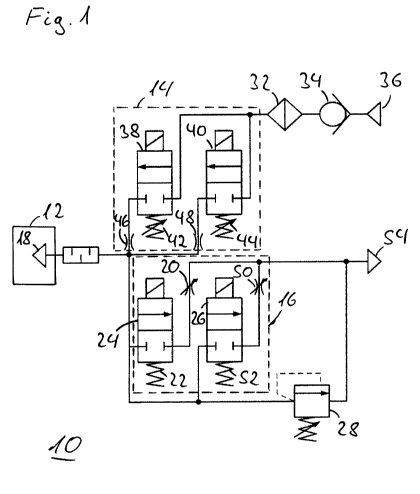
Figure 1 shows a first embodiment of a clutch system 10
according to the invention. In addition to the
components already described in conjunction with Figure
2, a safety valve 28 is provided, via which pressure
medium can be discharged from the switching chamber 18
to the deaeration connection 54 while bypassing the
second valve device 16. The coupling of the safety
valve 28 to the deaeration connection 54 is to be
understood as symbolic, and the safety valve 28 can in
particular have a separate deaeration connection and,
in particular, if compressed air is used as the
pressure medium, can discharge it directly into the
surroundings. If another pressure medium is used, for
CA 02784960 2012-06-19
- 10 -
example, hydraulic oil, the deaeration connection 54
typically corresponds to a return line, which returns
the used pressure medium into a reservoir (not shown)
of a closed pressure medium circuit. In relation to the
clutch system 10 already known from Figure 2, the first
valve device 14 has modified aeration valves 38, 40,
which comprise adapted restoring springs 42, 44. The
spring forces applied by the restoring springs 42, 44
are typically somewhat greater, i.e., the restoring
springs 42, 44 used are somewhat harder in order to
reduce the leakage flows occurring in the first valve
device 14 to a value which is less than the leakage
flow caused by the second valve device 16. The pressure
medium flow through the valve device occurring in spite
of a closed switching position of a valve device is
defined as the leakage flow. The basic principle of the
leak reduction is comprehensible in particular upon the
use of otherwise structurally-identical valves 38, 40,
24, 26 in the first and the second valve devices 14,
16, since then in the case of a harder restoring spring
42, 44, the leakage flow is reducible by the higher
contact pressure of a provided switching piston on the
associated valve seat. The spring force of the
restoring springs 42, 44 is only slightly modified in
relation to the restoring springs 42', 44' known from
Figure 2, so as not to lastingly influence the
switching characteristics of the aeration valves 38,
40. The adaptation of the spring force can alternately
be performed in only one or in both aeration valves.
Furthermore, throttles 20, 50 are provided in the
second valve device 16 in Figure 1, whose cross
sections are designed so that a release of pressure via
the second valve device 16 can occur more rapidly than
CA 02784960 2012-06-19
- 11 -
a buildup of pressure via the first valve device 14.
This can apply both in the case of open first valve
device 14 and open second valve device 16 and also in
the case of closed first valve device 14 and closed
second valve device 16. If both the first valve device
14 and also the second valve device 16 are closed, this
means that the leakage flow inflowing through the first
valve device 14 is less than the leakage flow possibly
outflowing through the second valve device 16, so that
a buildup of pressure in the switching chamber 18 is
avoided. If both the first valve device 14 and also the
second valve device 16 are in their open switching
positions, this means that a buildup of pressure in the
switching chamber 18 is also not possible, which, for
the case of a defect of only the first valve device 14,
for example, due to jamming of the aeration valves 38,
40 or due to another mechanical defect which destroys
the tightness of the first valve device 14, allows
emergency operation solely by switching the second
valve device 16. The adaptation of the throttle cross
section can alternately be performed in only one or in
both throttles 20, 50, only a small adaptation being
provided so as not to influence the pressure release
rates excessively strongly, since that would have
effects on the switching characteristics of the clutch
system 10.
Figure 2 shows a clutch switching system according to
the prior art, which was already described in the
introduction.
Figure 3 shows a second embodiment of a clutch system
according to the invention. In contrast to the first
embodiment known from Figure 1, the second embodiment
CA 02784960 2012-06-19
- 12 -
shown in Figure 3 comprises a second deaeration valve
26, which is not closed, but rather open in its
deenergized idle position. In case of a defect, in
particular a power failure, the first valve device 14
is accordingly in its closed switching position, while
the second valve device 16 at least has a second
deaeration valve 26, via which a more rapid release of
pressure is possible, so that a buildup of pressure in
the switching chamber 18 of the clutch actuator 12 by a
leakage flow of the first valve device 14 is not
possible.
Figures 4, 5, and 6 show a safety valve in three
different switching positions. The safety valve 28
shown in Figure 4 is arranged in a housing wall 30,
which tightly separates the switching chamber 18 from
surroundings 72. The housing wall 30 can also enclose
the remaining valve devices (not shown) of the clutch
system. The mechanism of the safety valve 28 is
arranged in a second bore 58, which partially overlaps
with a first bore 56. The first bore 56 is accessible
from the switching chamber 18, while the second bore 58
is accessible from the surroundings 72. Furthermore, a
deaeration channel 60 is provided, which connects the
switching chamber 18 through the housing wall 30 to the
surroundings 72, wherein the deaeration channel 60
preferably passes centrally through the second bore 58.
In the interior of the second bore 58, a control piston
64 is arranged so it is movable, which is held by a
spring 68, which is supported against a closure cap 70,
in its illustrated idle position. The control piston 64
has a deaeration bore 66, which can be aligned with the
deaeration channel 60 by axial displacement of the
control piston 64 in the second bore 58. In its
CA 02784960 2012-06-19
- 13 -
illustrated first switching position, the control
piston 64 of the safety valve 28 tightly closes the
deaeration channel 60, so that the switching chamber 18
is tightly separated from the surroundings 72. A
throttle 62 is arranged in the deaeration channel 60,
via which the pressure release rate of the open safety
valve 28 is settable. The closure cap 70 allows easy
access to the safety valve 28 for maintenance purposes.
The closure cap 70 is preferably fastened removably in
or on the lateral bore 58, for example, as a screw, in
particular a hollow screw, or as a hollow inserted
sleeve, whose diameter is greater than the diameter of
the second bore 58, so that the closure cap 70 is held
by a clamping action. The closure cap 70 can have an
opening to the surroundings 72, in order to also exert
a restoring force on the control piston 64 via the
ambient pressure.
In the first switching position of the safety valve 28
shown in Figure 4, the pressure P prevailing in the
switching chamber 18 is less than a first switching
pressure P1 required for actuating the safety valve 28.
The pressure P prevailing in the switching chamber 18
acts via the first bore 56 and the second bore 58 on a
control surface of the switching piston 64 against the
closing force applied by the spring 68. If the pressure
P in the control chamber 18 increases, the force
exerted on the control surface of the control piston 64
grows and the control piston 64 is moved to the right
in the figure against the force applied by the spring
68. If the pressure P in the switching chamber 18
corresponds to the first switching pressure P1, the
deaeration bore 66 arranged in the control piston 64
exposes the deaeration channel 60, so that a release of
CA 02784960 2012-06-19
- 14 -
pressure from the control chamber 18 into the
surroundings 72 can occur. This second switching
position is shown in Figure 5. As a result of the
release of pressure, the force exerted on the control
surface of the control piston decreases again until the
pressure P in the control chamber 18 is again less than
the first switching pressure P1. If the leakage flow of
the first valve device 14 corresponds to the pressure
release rate possible via the throttle 62, the safety
valve 28 remains permanently in the illustrated second
switching position.
If the pressure P in the switching chamber 18 increases
more rapidly than a release of pressure can occur via
the deaeration channel 60, wherein the pressure release
rate is settable by the throttle 62, the switching
piston 64 is displaced further to the right in the
drawing by the higher pressure P now provided, until at
a pressure P greater than a second switching pressure
P2, the switching piston 64 again conceals the
deaeration channel. In this third switching state,
which is shown in Figure 6, the safety valve 28 is
closed again. The safety valve 28 shown in Figures 4 to
6 is accordingly only in an open switching position for
pressures P which are between a first switching
pressure P1 and a second switching pressure P2. The
second switching pressure P2 is preferably less than a
switching pressure Pd required for actuating the clutch
actuator.
The features of the invention disclosed in the above
description, in the drawings, and in the claims may be
essential for implementing the invention both
individually and also in any arbitrary combination.
CA 02784960 2012-06-19
- 15 -
List of reference numerals
clutch system
12 clutch actuator
14 first valve device
16 second valve device
18 switching chamber
throttle
20' throttle
22 restoring spring
24 first deaeration valve
26 second deaeration valve
26' second deaeration valve
28 safety valve
housing wall
32 filter
34 check valve
36 supply connection
38 first aeration valve
38' first aeration valve
second aeration valve
40' second aeration valve
42 restoring spring
42' restoring spring
44 restoring spring
44' restoring spring
46 throttle
48 throttle
throttle
50' throttle
52 restoring spring
54 deaeration connection
56 first bore
58 second bore
CA 02784960 2012-06-19
- 16 -
60 deaeration channel
62 throttle
64 control piston
66 deaeration bore
68 spring
70 closure cap
72 surroundings