Note: Descriptions are shown in the official language in which they were submitted.
CA 02784977 2012-06-18
WO 2011/076777 - 1 -
PCT/EP2010/070350
Description
Rotor having a squirrel cage
The invention relates to a rotor having a squirrel cage
and permanent magnets distributed over the
circumference, with the rotor having a laminated core
which extends over the entire rotor region and has
longitudinally continuous rotor slots, with the
squirrel cage passing through the rotor slots over the
entire length of the laminated core, with the squirrel
cage being formed with cage bars which are situated,
preferably encapsulated, in the rotor slots and short-
circuiting rings which connect the cage bars on both
end faces of the laminated core, with the radius of a
rotor region being reduced by at least the radial
thickness of the permanent magnets. The invention also
relates to an electric motor having a rotor of this
kind and to a centrifugal pump which is equipped with
an electric motor of this kind. The invention also
relates to a method for operating an electric motor
which is equipped with a rotor of this kind and to a
method for producing a rotor of this kind and/or an
electric motor of this kind.
DE 3609 750 Al discloses an electrical machine which is
in the form of a combined synchronous/asynchronous
machine and has a stator and has a rotor which is
arranged in a rotatable manner in the stator. The rotor
is divided into three rotor regions as seen in the
axial direction, at least one of said rotor regions
being fitted with permanent magnets in the manner of a
synchronous rotor and at least one being provided with
a squirrel cage winding, which is situated in rotor
slots, in the manner of an asynchronous rotor. The
rotor has a laminated core which extends over all three
CA 02784977 2012-06-18
- 2 -
rotor regions and has longitudinally continuous rotor
slots and the radius of the laminated core having rotor
slots is reduced by at least the radial thickness of
the permanent magnet segments in the synchronous rotor
region. The step rotor shown is a special design of a
rotor which is correspondingly complicated in terms of
manufacture and is associated with high costs. In
addition, only the appropriate rotor regions are in
each case used for the respective mode of operation,
that is to say synchronous operation or asynchronous
operation, in this rotor design. A design of this kind
is therefore not expedient in respect of the
requirement for energy efficiency applicable today.
The rotor from US 4 454 438 has permanent magnets which
are arranged over the outer circumference of the rotor
core. Either a magnet ring is mounted on the laminated
core or the permanent segments are arranged in pockets.
A magnet ring is expensive and complicated to
manufacture and the permanent magnets which are to be
pressed into pockets have to be produced with an
accurate fit. This rotor also has a special design
which requires a large number of complicated working
steps in order to be produced.
The object of the present invention is to provide a
rotor which can be produced with a low level of
expenditure and in simple manner and at the same time
ensures efficient operation.
According to the invention, this object is achieved in
that the radius of the rotor over the entire length
between the short-circuiting rings is reduced in such a
way that the radial height of the cage bars or cage
webs which are connected to said cage bars is reduced,
and permanent magnets are mounted on the rotor. The
invention makes it possible to modify a commercially
available cage rotor by simple turning processing,
CA 02784977 2012-06-18
- 3 -
called turning or turning-in in the text which follows,
or generally by material-removing machining, with the
result that the magnets can then be fitted within the
clearance obtained by the process for reducing the
radius. Permanent magnets are mounted on the rotor
surface which is obtained by reducing the radius over
the entire length between the short-circuiting rings.
Since the cage rotor always has to be excessively
turned after the die-casting, no additional working
process is therefore required; rather, only somewhat
more material is removed. According to the invention,
it has been found that a turned starting cage also
provides a sufficient effect. A rotor which is obtained
by turning a commercially available cage rotor supports
both asynchronous starting and synchronous operation by
being fitted with permanent magnets. The invention
therefore allows for economical production of two
different types of motor since it is necessary to make
a decision as to whether a normal asynchronous motor
with a commercially available cage rotor design or a
modified permanent-magnet rotor is to be produced from
a turned cage rotor only during a production process.
The structural design therefore allows a production
line for two motor variants, both for asynchronous cage
rotor motors and permanent-magnet line start motors.
One refinement of the invention makes provision for the
permanent magnets to be secured by a binding or a,
preferably thin, non-magnetic sleeve. It is
advantageous here for the short-circuiting rings to be
partially turned, so that support surfaces are formed,
for example, on both sides of the laminated core. The
support surfaces serve to fix the binding or a support
of the non-magnetic rotor sleeve. The partially turned
short-circuiting rings serve to fix the start and end
of the binding or of the support of a thin non-magnetic
rotor sleeve. When a non-magnetic rotor sleeve is used,
it has likewise proven expedient to turn the short-
CA 02784977 2012-06-18
- 4 -
circuiting rings on one side only in an inner region
which faces the laminated core, so that a projection is
produced, this projection serving as a stop for the
rotor sleeve. Turning which takes place on both sides
only in the inner subregions of the short-circuiting
rings is possible with a rotor binding. As a result,
the short-circuiting rings are included in the design
of the rotor. Additional fixing means, for example end
plates, are not required.
The magnet surfaces which form the poles are
advantageously formed by component magnets, preferably
rare-earth component magnets, in particular by NdFeB
magnets. The use of rare-earth magnets allows for a
comparatively low magnet height, this being
advantageous for the effect of the turned starting
cage. It has proven expedient for the magnet height to
be between 5% and 20%, preferably approximately 10%, of
the cage bar height. In the examined power range, a
magnet height of approximately 2 mm has proven
expedient. Rare-earth magnets also have a high
stability to opposing fields, this leading to said
rare-earth magnets not being demagnetized on account of
high magnetic fields which produce starting currents.
The component magnets can be arranged so as to be
offset or staggered in relation to one another in the
axial direction. A staggered arrangement of adjacent
component magnets in this way leads to a reduction in
the torque ripple during operation of the rotor on
account of the contact slot offset which is produced.
According to a further refinement, the rotor coverage
with permanent magnets, that is to say the pole
coverage, is between 65 and 90%, preferably between 70
and 80%. It has proven expedient to not completely fit
the rotor with magnets in the circumferential
direction, but rather to select a pole coverage of
between 65 and 90%, preferably between 70 and 80%.
CA 02784977 2012-06-18
- 5 -
Further refinements of the invention relate to an
optimized rotor slot shape. It has proven expedient
here to design the rotor slot shape in such a way that
the rotor slot shape results in good motor operation
properties both in the turned state and in the unturned
state of the cage rotor. It has proven expedient when
the cage bars of the turned rotor retain their original
shape. In particular, the cage bars of the turned rotor
are formed in the shape of a drop.
Proceeding from a conventional rotor having a squirrel
cage, with the rotor having a laminated core which
extends over the entire rotor region and has
longitudinally continuous rotor slots, with the
squirrel cage passing through the rotor slots over the
entire length of the laminated core, the squirrel cage
being formed with cage bars which are situated,
preferably encapsulated, in the rotor slots and short-
circuiting rings which connect the cage bars on both
end faces of the laminated core, provision is made,
according to the invention, for the rotor to have, in
particular slot-like, cage webs in a radially outer
region, preferably in accordance with at least the
radial thickness of permanent magnets which are to be
mounted in the case of a synchronous rotor, said cage
webs being connected to, in particular drop-shaped,
cage bars which are situated in a radially inner region
of the rotor. As a result, it is possible for the
radius of the asynchronously operated rotor to be
reduced over the entire length between the short-
circuiting rings by at least the radial thickness of
permanent magnets which are to be mounted in the case
of a synchronous rotor which is to be manufactured, in
such a way that the radial height of the cage webs
which are connected to the cage bars is reduced, and
the cage bars retain their shape. The unturned rotor
has rotor slots for this purpose, said rotor slots
= CA 02784977 2012-06-18
- 6
forming, in particular slot-like, cage webs in a
radially outer region, preferably in accordance with at
least the radial thickness of the permanent magnets,
and, in particular drop-shaped, cage bars in a radially
inner region. In this case, the lower, in particular
drop-shaped, design of the cage bar is designed to
match the web contour, in particular the slot.
Experiments have shown that it is expedient to design
the, in particular drop-shaped, bar contour in the
upper region to be somewhat wider and, for this,
altogether shorter than usual.
The invention comprises not only the rotor but also
includes an electric motor which is equipped with a
rotor according to the invention.
A centrifugal pump having an electric motor and also a
centrifugal pump arrangement comprising at least one
centrifugal pump and at least one electric motor
characterized by at least one electric motor and/or
rotor according to the invention is likewise covered by
the scope of the invention. By way of example, canned
motor pumps and underwater motor pumps which are
equipped with an electric motor according to the
invention can be operated in an energy-efficient manner
by the invention.
On account of the self-starting properties of the rotor
according to the invention, an electric motor which is
equipped with said rotor and/or a centrifugal pump with
an electric motor of this kind can be fed by a single-
phase or polyphase fixed voltage supply system, that is
to say are operated directly from a voltage supply
system with a fixed frequency.
A further method makes provision for the electric motor
to be fed by a frequency converter, preferably without
the position of the rotor being detected. The rotation
CA 02784977 2012-06-18
- 7 -
speed of the electric motor can be controlled in a
variable manner by the frequency converter. In this
case, the invention makes it possible to allow the
electric motor to be fed by a frequency converter of
conventional, that is to say not specialized, design.
For drive purposes, detection of the rotor position can
be dispensed with, this considerably simplifying the
design of the frequency converter. Conventional
converters with U/f characteristic curve control can be
used. In the case of asynchronous operation, as occurs
in the event of a crack in the permanent-magnet rotor,
voltages are induced in the cage of the rotor which
result in current flow. A force effect is exerted on
the rotor together with the magnetic flux lines of the
stator, and therefore the rotor again assumes the
synchronous rotation speed which can be varied by the
U/f converter.
A method according to the invention for producing a
rotor or an electric motor according to the invention
makes provision, in the case of a cage rotor which is
manufactured in a conventional manner, for the radial
diameter or radius to be additionally reduced over the
entire length of the laminated core beyond the
conventional air gap by a material-removing method, in
particular a turning-in process, during which process
the radius of said cage rotor is reduced over the
entire length between the short-circuiting rings in
such a way that the radial height of the cage bars of
said cage rotor or cage webs which are connected to
said cage bars is reduced, and then permanent magnets
are mounted on the rotor surface. A commercially
available cage rotor is modified by simple turning
machining, so that the magnets can then be mounted. A
conventionally produced cage rotor does not have to be
excessively turned after die-casting in order to
acquire an air gap in the state in which it is
incorporated in the stator. Therefore, no additional
CA 02784977 2017-01-20
53598-13
- 8 -
working process is required by the invention; rather, only
somewhat more material is removed.
It has proven expedient to adhesively bond the permanent
magnets in the clearance, in particular the groove, which is
produced by reducing the radius. In addition to fastening the
magnets to the rotor, the adhesive bonding of the magnets
serves to electrically isolate the magnets and the laminated
rotor core with cage bars on account of the adhesive film which
is produced. In the case of small quantities, shell magnets
which have already been magnetized can be manually fitted.
A method according to which the permanent magnets, which are
preferably mounted on the cage rotor automatically, are
magnetized by means of a magnetizing yoke is suitable for
larger quantities.
A binding or a, preferably thin, non-magnetic sleeve can be
mounted on the permanent magnets in order to secure the
permanent magnets. In this case it is advantageous for the
short-circuiting rings to likewise be turned and the binding or
the non-magnetic sleeve to be fixed or supported by the short-
circuiting rings. The turned short-circuiting rings therefore
form a support surface or projection surface for fixing the
start and/or end of the binding or the sleeve.
In some embodiments, there is provided a rotor having a
squirrel cage and permanent magnets distributed over the
circumference, with the rotor having a laminated core which
extends over the entire rotor region and has longitudinally
continuous rotor slots, with the squirrel cage passing through
the rotor slots over the entire length of the laminated core,
81626994
- 8a -
with the squirrel cage being formed with cage bars which are
situated in the rotor slots and short-circuiting rings which
connect the cage bars on both end faces of the laminated core,
with the radius of a rotor region being reduced by at least the
radial thickness of the permanent magnets, wherein the radius
of the rotor over the entire length between the short-
circuiting rings is reduced by turning in such a way that the
radial height of the cage bars or cage webs which are connected
to said cage bars is reduced, and permanent magnets are mounted
on the rotor.
In some embodiments, there is provided a method for producing a
rotor or an electric motor comprising the rotor, wherein, in
the case of a cage rotor which is manufactured in a
conventional manner, the radius is reduced over the entire
length of the laminated core by a material-removing method
during which process the radius of said cage rotor is reduced
by turning over the entire length between the short-circuiting
rings in such a way that the radial height of the cage bars of
said cage rotor or cage webs which are connected to said cage
bars is reduced, and then permanent magnets are mounted on the
rotor surface.
In some embodiments, there is provided an electric motor
comprising a rotor as described herein or a rotor produced as
described in a method as described herein.
In some embodiments, there is provided a centrifugal pump
arrangement comprising an electric motor as described herein.
In some embodiments, there is provided a method for operating
an electric motor as described herein and/or a centrifugal pump
CA 2784977 2017-12-13
81626994
- 8b -
arrangement as described herein, wherein the electric motor is
fed by a voltage supply system with a fixed frequency.
In some embodiments, there is provided a method for operating
an electric motor as described herein and/or a centrifugal pump
arrangement as described herein, wherein the electric motor is
fed by a frequency converter without the position of the rotor
being detected.
Exemplary embodiments of the invention are illustrated in the
drawings and will be described in greater detail below. In the
drawings
fig. 1
shows a schematic sectional illustration of a cage
rotor active part according to the prior art,
CA 2784977 2017-12-13
CA 02784977 2012-06-18
- 9 -
fig. 2 shows a schematic sectional illustration
of a rotor according to the invention
having additional magnets fitted,
fig. 3 shows a schematic sectional illustration
of another rotor according to the
invention having short-circuiting rings
which form support surfaces,
fig. 4 shows another sectional illustration of a
rotor having turned-in cage bars,
figs 5 a, b show sectional illustrations of a rotor
which is not turned-in and has an
optimized rotor slot shape and a turned-in
rotor which is produced from said rotor,
fig. 6 shows a plan view of a rotor with magnets
arranged so as to be offset in the axial
direction, and
fig. 7 shows a basic illustration of a drive
concept of a centrifugal pump arrangement
having an electric motor which is equipped
with a rotor according to the invention.
Fig. 1 shows a schematic sectional illustration of a
cage rotor active part 1 of a cage rotor according to
the prior art. A rotor shaft is not illustrated for
reasons of clarity. Cage bars 5, which are connected at
both ends of the rotor active part 1 by short-
circuiting rings 7, are located within a laminated
rotor core 3. In this case, the cage bars 5 pass
through the rotor slots over the entire length of the
laminated core 3. In this case, the cage bars 5 which
are encapsulated in the rotor slots and the short-
circuiting rings 7 which connect the cage bars 5 on
both end faces of the laminated core 3 form a squirrel
CA 02784977 2012-06-18
*
- 10 -
cage. A cage rotor of this kind is usually produced by
aluminum or copper pressure die-casting. The required
geometric air gap between the stator of an electric
motor and the rotor 1 is usually obtained by turning
the rotor.
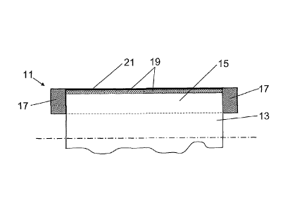
Fig. 2 shows - again in a schematic sectional
illustration - a rotor 11 according to the invention
which is produced from a cage rotor active part 1
according to the prior art. The rotor 11 has a
laminated rotor core 13, cage bars 15 and short-
circuiting rings 17. The radius of the laminated rotor
core 13 of the rotor 11 according to the invention is
reduced over the entire length between the short-
circuiting rings 17 by material-removing machining in
such a way that the radial height of the cage bars 15
is reduced. Permanent magnet shells 19 are mounted in
the laminated rotor core 13, said permanent magnets
being secured by a rotor binding 21 in this exemplary
embodiment. The rotor 11 is produced by further
processing of a cage rotor 1 according to the prior art
by, in addition to material-removing machining, in
particular turning or turning-in, additional material-
removing machining, in particular turning or turning-
in, being performed in order to obtain the required
geometric air gap between the stator of an elect_ric
motor and the rotor on the rotor core. The shell
magnets 19 are then adhesively bonded in the clearance,
in particular the groove, which is produced by
material-removing machining. The shell magnets 19 may
already be magnetized, but subsequent magnetization of
the shell magnets by means of a magnetizing yoke is
also provided for. After the shell magnets 19 are
fitted, the rotor obtains a binding 21 for securing the
magnets 19. As an alternative, the magnets can be
secured by a, preferably thin, non-magnetic sleeve.
This sleeve can be pushed, for example, over the magnet
shells.
CA 02784977 2012-06-18
- 11 -
Fig. 3 shows an alternative refinement of a cage rotor
11. In this figure, the short-circuiting rings 17 are
partly turned, so that support surfaces 23 are formed
on both sides of the laminated core 13. The support
surfaces 23 serve to fix the binding 21 or to support a
non-magnetic rotor sleeve. When a non-magnetic rotor
= sleeve is used, it has likewise proven expedient to
turn the short-circuiting rings on one side only in an
inner region which faces the laminated core, so that a
projection is produced, this projection serving as a
stop for the rotor sleeve. Turning which takes place on
both sides only in the inner subregions of the short-
circuiting rings is possible with a rotor binding. As a
result, the short-circuiting rings 17 are included in
the design of the rotor, and additional fixing means,
for example end plates, are not required.
Fig. 4 shows another sectional illustration of a rotor
11 with turned-in cage bars 15. The turned-in or turned
cage bars 15 in the laminated rotor core 13 can be
clearly seen in this illustration. Magnet shells 19 are
adhesively bonded onto the rotor surface 16, with the
adhesive means serving as an insulation means. In this
case, the adhesive film separates the magnets 19 from
the rotor surface 16 of the turned rotor 11 in an
electrically insulating manner. A binding or a non-
magnetic stainless steel sleeve 21 is provided for
fixing the magnetic shells 19. According to the
invention, the radius of the rotor 11 is reduced over
the entire length between the short-circuiting rings 17
of said rotor, so that the radial height of the cage
bars 15 is likewise reduced over the entire length
between the short-circuiting rings 17, so that the
permanent magnets 19 can be mounted on the laminated
core 13. According to the invention, it has been found
that a turned starting cage also provides a sufficient
effect. A rotor which is produced by turning a
CA 02784977 2012-06-18
- 12 -
commercially available cage rotor supports both
asynchronous starting and synchronous operation by
being fitted with permanent magnets. The invention
therefore allows for economical production of two
different types of motor, with it being necessary to
make a decision as to whether a normal asynchronous
motor with a commercially available cage rotor design
or a modified permanent-magnet rotor of synchronous
design is to be produced from a turned cage rotor only
during a production process.
The rotor 11 is not entirely fitted with magnets 19 in
the circumferential direction, but rather has a pole
coverage of between 70 and 80%. A plurality of magnet
shells 19 form a magnet pole in this case. Magnet
surfaces which form the poles are advantageously formed
by component magnets which are composed of rare-earth
material, in particular of NdFeB magnets. When rare-
earth magnets are used, a comparatively low magnet
height is required to achieve a sufficient effect.
Furthermore, magnets of this kind have a high stability
to opposing fields, this leading to said magnets not
being demagnetized on account of high magnetic fields
which produce starting currents either.
Fig. 5a shows a sectional illustration of an unturned
rotor 10 having an optimized rotor slot shape. The
rotor slot shape used in this exemplary embodiment is
distinguished by an enlarged web region 27 and deep
cage bars 29. The rotor 10 therefore has pronounced or
enlarged cage webs 27. A rotor slot shape of this kind
ensures good motor operating properties both in the
unturned state and in the turned state of the rotor 11.
The unturned rotor 10 specifically has rotor slots
which are in the form of slot-like webs in a radially
outer region 28, preferably in accordance with at least
the radial thickness of the permanent magnets, and are
in the form of drop-shaped bars in a radially inner
CA 02784977 2012-06-18
- 13 -
region 30. In this form, the rotor 10 is suitable as a
rotor for a cage rotor of an asynchronous machine.
Fig. 5b shows a rotor 11 of synchronous design which is
produced from a rotor 10 according to fig. 5a. The
drop-shaped bars 29 which are situated relatively deep
in the laminated rotor core 13 completely retain their
shape even after turning. This results in good motor
operating properties. The turning depth between the
radius of the asynchronous rotor 10 and the radius of
the synchronous rotor 11 differ only in respect of the
height of the magnets 19, the thickness of a binding 21
which is conventionally provided, and the difference in
the air gap widths between the two motors. It can be
seen that, in the optimized rotor slot shape shown
according to fig. 5a, the cage bars retain the drop
shape in the turned rotor according to fig. 5b, this
producing good motor operating properties. The
invention provides a building block concept by means of
which, only when a rotor is produced, a decision has to
be made as to whether a conventional motor with
asynchronous technology or a motor with synchronous
technology is intended to be produced.
Fig. 6 shows a plan view of a rotor 11 which is
arranged on a shaft 25. Said figure shows the short-
circuiting rings 17 on both end faces of the laminated
core and the magnets 19 which are mounted on the turned
rotor 11 and the rotor surface 16 of said rotor. The
magnets 19 are distributed uniformly or symmetrically
on the rotor surface 16 in the circumferential
direction. A magnet pole is formed from a plurality of
component magnets. The component magnets are arranged
so as to be offset or staggered in relation to one
another in the axial direction. This staggered
arrangement of adjacent component magnets leads to a
reduction in the torque ripple during operation of the
CA 02784977 2012-06-18
- 14 -
rotor 11 on account of the contact slot offset which is
produced.
Fig. 7 shows a centrifugal pump arrangement 2 having an
electric motor 33 which is equipped with a rotor 11
according to the invention, and a basic illustration of
a drive concept of the centrifugal pump arrangement 2.
A centrifugal pump 31 is driven by an electric motor
33, which is equipped with a rotor according to the
invention, via a shaft 25. On account of the self-
starting properties of the rotor according to the
invention, the electric motor 33 which is equipped with
said rotor and/or the centrifugal pump 31 can be fed by
a single-phase or polyphase fixed voltage supply system
35, that is to say can be operated directly from the
voltage supply system 35 with a fixed frequency. In
this exemplary embodiment, the rotation speed n of the
electric motor 33 is controlled in a variable manner by
a frequency converter 37. In this case, the electric
motor 33 is fed by a frequency converter 37 of
conventional, that is to say not specialized, design.
In order to drive the electric motor which is equipped
with a rotor according to the invention, detection of
the rotor position can specifically be dispensed with,
as a result of which a conventional converter 37 with
U/f characteristic curve control can be used. This
drive concept is suitable for centrifugal pumps with a
variable rotation speed and allows operation at the
converter without the position of the rotor being
detected. Emergency operation at the fixed three-phase
power supply system is also possible. Therefore, simple
U/f converters can be used, as are usually used in pump
drives with asynchronous technology. A transmitter
system for detecting the position of the rotor is not
required and therefore the signal line between the
motor and converter and the evaluation electronics in
the converter which are otherwise additionally required
are also dispensed with. A high level of energy
CA 02784977 2012-06-18
- 15 -
efficiency is achieved in the case of stationary
synchronous operation on account of the permanent-
magnet excitation.