Note: Descriptions are shown in the official language in which they were submitted.
CA 02785045 2012-07-30
LIGHTNING PROTECTION
AIRCRAFT SKIN ASSEMBLY
This is a divisional of Canadian patent application
serial no. 2,703,575, which is the national phase of
International application no. PCT/JP2009/055712 filed March
23, 2009 and published October 1, 2009 under publication no.
WO 2009/119526 Al.
Technical Field
[0001]
The present invention relates to an aircraft assembly,
such as a main wing and a fuselage of an aircraft, having a
lightning protection structure.
Background Art
[0002]
A lightweight, high-strength, and durable material is
required as the material for the airframe (skin) of an
aircraft, and, in recent years, there has been an increasing
use of fiber-reinforced resins (composite materials).
As such composite materials, for example, carbon-fiber
reinforced plastic (CFRP) in which carbon fibers are hardened
with epoxy resin, etc., and glass-fiber reinforced plastic
(GFRP) in which glass fibers are hardened with epoxy resin,
etc., are often used.
With these composite materials, there is a problem in
that they have lower resistance against a lightning strike as
compared with metal. In addition, because fasteners for
securing a skin to an internal structural member are made of
CA 02785045 2012-07-30
2
metal (for exam)le, titanium alloy), there is a risk of flash
(spark) generation therein via electric current generated by a
lightning strike (lightning current--) passing through the
fasteners.
[0003]
Accordingly, when using a composite material in a skin,
it is required to make a structure in consideration of
lightning protection properties, especially a structure that
prevents lightning from passing through the fasteners.
As such lightning protection structures, for example, the
disclosures of Patent Citations 1 and 2 have been proposed.
The structure disclosed in Patent Citation 1 has an
insulating cap attached to an outside end of the head of a
fastener, and there have been many proposals for preventing
the passage of lightning with such modifications to the
structure of a fastener.
In the structure disclosed in Patent Citation 2, a metal
strap (conductive layer) is attached around a fastener and an
insulation layer is provided above the head of the fastener,
thereby dispersing the lightening current due to a lightning
strike over the skin surface.
[0004]
Patent Citation 1: United States Patent, No. 4,630,168,
specification.
Patent Citation 2: United States Patent, No. 5,845,872,
CA 02785045 2012-07-30
3
specification.
Disclosure of invention
[0005]
However, with the disclosure of Patent Citation 1, the
insulating caps are positioned at the surface of the skin, and
there is a problem in that, when lightning current flows along
the surface, the lightning current has to flow around these
insulating caps, and the flow of the lightning current is thus
obstructed.
In addition, the configuration in the disclosure of
Patent Citation 2 is such that only one metal foil layer is
provided as the conductive layer for dispersing lightning
current; therefore, there is a risk of it being easily
destroyed by the lightning current. Furthermore, there is a
problem with a metal foil in that, although it depends on the
thickness thereof, the conveying capacity for conveying the
lightning current without being destroyed is small.
[0006]
The present invention has been conceived in light of the
above-described circumstances, and an object thereof is to
provide an aircraft assembly provided with a lightning
protection structure that is not easily destroyed by lightning
current and that is highly reliable.
[0007]
CA 02785045 2012-07-30
4
In order to solve the above-described problems, an
aircraft assembly of the present invention employs the
following solutions.
That is, a first aspect of an aircraft assembly according
to the present invention is an aircraft assembly that includes
a skin in which fiber reinforced resin serves as a main
structure; a structural member that supports the skin from the
inside; and a fastener that couples the skin and the
structural member; wherein a conductive foil is provided on an
outer surface side of the skin, and a conductive resin layer
containing conductive powder is provided above the conductive
foil.
[00081
When an aircraft assembly is hit by a lightning strike,
an electric current generated by the lightning strike
(hereinafter, referred to as "lightning current") flows in the
conductive resin layer located at an upper layer. As compared
with a conductive foil, this conductive resin layer, because
it is formed of resin containing conductive powder, has a
larger conveying capacity for the lightning current and has a
higher capacity for dispersing the lightning current.
Therefore, it is possible to minimize the damage caused by a
lightning strike.
In addition, because a conductive foil is provided below
the conductive resin layer, even in an unlikely event of the
CA 02785045 2012-07-30
J
conductive resin layer being destroyed by a lightning strike,
the lightning current can be dispersed by this conductive
foil. Furthermore, the conductive foil is not mesh-like, but
is a planar sheet uniformly extending with a predetermined
sectional area; therefore, the capacity thereof for conveying
the lightning current is superior as compared with the mesh-
like ones.
Note that, as the "conductive resin layer", a phenol
resin with copper particles mixed therein is preferable.
[0009]
Furthermore, in the above-described first aspect, the
fastener may be inserted into an insertion hole that
penetrates through the main structure of the skin, the
conductive foil, and the structural member; and a head portion
of the fastener located on the outer surface side of the skin
may have the conductive resin layer coated thereon.
[0010]
The fasteners are disposed inserted in the insertion
holes that penetrate through the main structure of the skin,
the conductive foil, and the structural member. The top of
the head portion of the fasteners is coated with the
conductive resin layer. Accordingly, it is possible to
prevent the lightning current from penetrating into the
fasteners.
Note that in order to improve the lightning protection
CA 02785045 2012-07-30
6
property of the fasteners, it is preferable that at least a
portion of the exterior of the fastener heads be formed of
insulating material. As this insulating material, a
thermoplastic polyimide resin, PEEK, or the like, is
preferable.
[0011]
Furthermore, in the above-described first aspect, the
fastener may have a tip portion that protrudes further inside
from the structural member; the tip portion may be provided
with a fixture that is inserted into the tip portion to secure
the skin and the structural member; an insulating washer
having a surface coated with an insulating material may be
interposed between the structural member and the fixture; and
an insulating spacer may be interposed between the structural
member and the insulating washer.
[0012]
In addition to an insulating washer whose surface is
coated with an insulating material, an insulating spacer is
provided; therefore, insulation can be ensured by the
insulating spacer even if the insulating coating of the
insulating washer peels off due to a shearing force exerted by
deformation at the time of assembly. In this way, reliability
is improved by doubly insulating with the insulating washer
and the insulating spacer.
Additionally, when the lightning current passes through
CA 02785045 2012-07-30
7
the fastener, there is a risk of spark occurrence in a minute
gap between the fixture (for example, a nut) and the
structural member. in the present invention, by interposing
the insulating washer and the insulating spacer between the
fixture and the structural member, a spark is prevented from
occurring in the minute gap. Specifically, by adopting such a
configuration that the insulating spacer is compressively
deformed by the structural member and the insulating washer,
it is possible to absorb an uneven minute gap created by
errors during mounting of the fastener.
As the insulating spacer, polyimide is suitable, and it
is further preferable that the configuration thereof be such
that a plurality of sheets are laminated in the direction in
which the compressive force is applied. This is because, with
a configuration with a plurality of sheets, even if one layer
of the sheets is damaged, the sheets in the other layers
function effectively.
[0013]
Furthermore, in the above-described first aspect, an
insulating sealant may be provided between the fastener and
the insertion hole.
[0014]
By providing the insulating sealant between the fastener
and the insertion hole, the insulating properties can be
further enhanced between the fastener and the skin.
CA 02785045 2012-07-30
7a
[0014a]
In a further aspect, the present invention provides an
aircraft assembly comprising: a skin in which fiber reinforced
resin serves as a main structure; a structural member that
supports the skin from the inside; and a fastener that couples
the skin and the structural member; wherein the fastener has a
tip portion that protrudes further inside from the structural
member; the tip portion is provided, via an insulating washer
having a surface coated with an insulating material, with a
fixture that is inserted into the tip portion to secure the
skin and the structural member; and an insulating spacer is
interposed between the structural member and the insulting
washer.
CA 02785045 2012-07-30
8
Note that with the insulating sealant provided between
the fastener and the insertion hole, the fastener is not
accurately positioned relative to the insertion hole when
~nsert~ng the fastener thereinto. Specifically, the fastener
is inserted into the insertion hole after the insulating
sealant is applied to the fastener which is then fixed thereto
by solidifying the insulating sealant; therefore, at the time
of insertion, the fastener is not positioned in contact with
the insertion hole. In other words, at time of insertion, the
fastener is loosely fitted into the insertion hole (so-called
clearance fit). Because the relative position between the
insertion hole and the fastener is not accurately determined
with such a clearance fit, an unintended uneven minute gap
forms between the fastener and the fixture, becoming the cause
of a spark. If the insulating spacer, which is compressed by
the structural member and the insulating washer, is provided
in such a case, even with a clearance fit, an uneven
distribution of the minute gap can be prevented by compressive
deformation of the insulating spacer, thereby preventing spark
occurrence.
[0015]
Furthermore, a second aspect of an aircraft assembly of
the present invention is an aircraft assembly that includes a
skin in which fiber reinforced resin serves as a main
structure; a structural member that supports the skin from the
CA 02785045 2012-07-30
a,
inside; and a fastener that couples the skin and the
structural member; wherein the fastener has a tip portion that
protrudes further inside from the structural member; the tin
portion is provided, via an insulating washer having a surface
coated with an insulating material, with a fixture that is
inserted into the rip portion to secure the skin and the
structural member; and an insulating spacer is interposed
between the structural member and the insulating washer.
[00161
In addition to an insulating washer whose surface is
coated with an insulating material, an insulating spacer is
provided; therefore, insulation can be ensured with the
insulating spacer even if the coating of insulating material
on the insulating washer peels off due to a shearing force
exerted by deformation at the time of assembly. in this way,
reliability is improved by doubly insulating with the
insulating washer and the insulating spacer.
Additionally, when the lightning current passes through
the fastener, there is a risk of spark occurrence in a minute
gap between the fixture (for example, a nut) and the
structural member. in the above-described second aspect, by
interposing the insulating spacer and the insulating washer
coated with the insulating material between the fixture and
the structural member, a spark is prevented from occurring in
the minute gap. Specifically, by adopting such a
CA 02785045 2012-07-30
configuration that the insulating spacer is compressively
deformed by the structural member and the insulating washer,
it is possible to absorb an uneven minute gap created by
errors during mounting of the fastener.
As the insulating spacer, polyimide is suitable, and it
is further preferable that the configuration thereof be such
that a plurality of sheets are laminated in the direction in
which the compressive force is applied. This is because, with
a configuration with a plurality of sheets, even if one layer
of the sheets is damaged, the sheens in the other layers
effectively function.
[0017]
With the present invention, the following effects and
advantages are afforded.
Because the conductive resin layer is provided along with
the conductive foil provided therebelow, it is possible to
obtain an aircraft assembly equipped with a lightning
protection structure that is not easily destroyed by the
lightning current and is highly reliable.
in addition, the insulating washer and the insulating
spacer are interposed between the fixture and the structural
member, thereby making it possible to improve reliability by
double insulation.
Brief Description of Drawings
CA 02785045 2012-07-30
[0018]
[Fig. 1] Fig. 1 is a plan view showing a main wing, which is
an aircraft assembly of the present invention.
[Fig. 2] Fig. 2 is a sectional view, schematically showing the
positional relationship between a shear-tie and a skin.
[Fig. 3] Fig. 3 is a sectional view showing Fig. 2 in more
detail.
[Fig. 4] Fig. 4 is a lateral sectional view of a fastener
according to the present embodiment, with a portion thereof
shown in cross section.
[Fig. 5] Fig. 5 is a sectional view of aluminum tape used as
Comparative Example 1 in the embodiments.
Explanation of Reference:
[0019]
1 fastener
skin
11 shear-tie (structural member)
13 copper foil (conductive foil)
14 outer GFRP layer (insulation layer)
17 collar (fixture)
18 insulating sealant
19 copper paint layer (conductive resin layer)
21 insulating washer
22 insulating spacer
CA 02785045 2012-07-30
12
Best Node for Carrying Out the Invention:
[0020)
An embodiment according to the present invention will be
described below, referring to the drawings.
Fig. I shows a plan view of a main wing (aircraft
assembly) A of an aircraft. A rib line B includes a position
at which a shear-tie (structural member) 11, described later,
is disposed, and shows a region where copper paint (conductive
resin layer) 19 or a copper foil (conductive foil) 13,
described later, is disposed.
[0021)
Fig. 2 schematically shows the positional relationship
between a skin 10 and the shear-tie (Sea-Tie) 11. The shear-
tie 11 is a member that joins the skin 10 and a stringer, a
rib, and so on, and is assumed to be of a conductive material,
such as aluminum alloy or titanium ally, or CFRP (carbon-fiber
reinforced plastic). The skin 10 and the shear-tie 11 are
fixed with a fastener 1. Specifically, a collar (nut) 17 is
screwed on the tin of the fastener 1, thereby fastening the
skin 10 and the shear-tie 11 to secure them together.
An insulating washer 21 and an insulating spacer 22 are
interposed between the collars 17 and the shear-ties 11.
As shown on the right side of Fig. 2, the collar 17, the
insulating washer 21, and the insulating spacer 22 are
entirely covered by an insulating cap 24 that is formed of an
CA 02785045 2012-07-30
3
insulating material such as resin, etc. The insulating can 24
can also serve dual purpose as a fuel seal by being secured _Jr
close contact with the shear-ties 11.
0022]
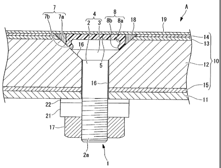
Fig. 3 shows the section shown in Fig. 2 in more detail.
In addition, Fig. 4 is a cross-sectional view of the fastener
As shown in Figs. 3 and 4, the fastener 1 is constituted
mainly of a fastener main body 4, which has a cylindrically
shaped shaft portion (shank) 2; a head portion (flush head:
flush head) 3 provided at one end of the shaft portion 2 and
having a substantially frustoconical form whose diameter
increases with increasing distance from the shaft portion 2;
and an insulating head portion 5 positioned at one end (top
portion located at the upper side of Figs. 3 and 4) of she
head portion 3.
[0023]
The fastener main body 4 is integrally formed of the
shaft portion 2 and the head portion 3 and is fabricated using
an alloy of, for example, titanium (Ti-6A2-4V: annealed
material), Inconel, or the like.
A male screw portion 2a that is threaded to a female
screw portion of a cellar (nu-, fixture), described later, is
formed on the other end (end portion at lower side in Figs. 3
and 4) of the shaft portion 2.
CA 02785045 2012-07-30
14
A fastener-side engagement portion 7, to which the
insulating head portion 5 is secured, is provided at the top
portion of the head portion 3. The fastener-side engagement
portion 7 is located on the opposite side from the shaft
portion 2 (the upper side in rigs. 3 and 4), and is provided
with a convex portion 7a that protrudes radially outward
around the circumferential direction (increases in diameter)
and a concave portion 7b that connects (joins) the shaft
portion 2 and the convex portion 7a and that is depressed
radially inward around the circumferential direction.
Note that the diameter of the head portion 3 at one end
surface is, for example, about 12.7 mm (1/2 inch).
[0024]
The insulating head portion 5 is assumed to be a disk-
like member. As a material for the insulating head portion 5,
for example, a thermoplastic polyimide resin (for example,
AURUM that can be obtained from Mitsui Chemicals, inc.), which
has superior heat-resistance and strength, is suitable.
Examples of materials other than this include other
thermoplastic resins (for example, polyether-imide (PE1)
having heat resistance and strength in addition to a high
dielectric breakdown voltage, polyether-ether-ketone (PEEK)
having superior heat resistance and strength in addition to
superior formability and versatility, polyphenylsulfide (PPS)
having heat resistance and strength in addition to superior
CA 02785045 2012-07-30
formability and versatility; and nolyamide-imide (PAT) having
particularly superior heat resistance and strength)) and
thermosetting resins, etc.
An insulation-laver-side engagement portion 8, which is
secured to the 'fastener-side engagement portion 7, Js provided
on a circumferential edge portion (end portion at the lower
side in Figs. 3 and 4) of the insulating head portion 5. The
insulation-layer-side engagement portion 8 is provided with a
concave portion 8a that is depressed radially inward around
the circumferential direction and that couples with the convex
portion 7a of the fastener-side engagement portion 7 and a
convex portion 8b that protrudes (increases in diameter)
radially outward around the circumferential direction and that
couples with the concave portion 7b of the fastener-side
engagement portion 7
In addition, the insulating head portion 5 is formed by
injection molding so as to be attached to the fastener-side
engagement portion 7 of the head portion 3. Accordingly,
outer surfaces of the fastener-side engagement portion 7 and
inner surfaces of the insulation-layer-side engagement portion
8 are in close contact over the entirety thereof; therefore,
the insulating head portion 5 is firmly secured to the head
portion 3 by the adhesive force possessed by the insulating
head portion 5 itself.
Note that it is desirable to make the plate thickness of
CA 02785045 2012-07-30
16
the insulating head portion 5 (`.he length between the top
surface (the flat surface located at the upper site in Figs. 3
and 4) and the bottom surface (the flat surface located at the
lower side in Figs. 3 and 4), for example, about 0.5 mm to 1.0
mm, so as to provide sufficient dielectric strength even
against the MIL-STD-1757A Zone 1 stroke test voltage (about 40
kV).
[0025]
The skin 10 is mainly constructed of a CFRP (carbon-fiber
reinforced plastic) layer 12, which is a resin material having
conductivity (conductivity of about 1/100 to 1/1000 that of
aluminum) . The entire outer surface (the surface located on
the outside after assembly) of the CFRP laver 12 is provided
with an outside GFRP layer 14, which is GFRP (glass-fiber
reinforced plastic) having insulating properties, and the
entire inner surface (the surface located inside after
assembly) of the CFRP layer 12 is coated with an inside GFRP
_ayer 15.
n addition, a copper foil (conductive foil) 13, which
has conductivity as a whole, is provided between the CFRP
layer 12 and the outside GFRP layer 14. The thickness of the
copper foil 13 is assumed to be about 70 pi .
[00261
The shear-ties 11 are made of, for example, aluminum
alloy, titanium material, or CFRP (carbon-fiber reinforced
CA 02785045 2012-07-30
ii
plastic) and are disposed at a predetermined position on the
back surface (the surface located inside after assembly) of
the inside GFRP 15.
Insertion holes 16, which are capable of receiv?nc the
..fasteners 1, are formed at predetermined positions of the
structural member, at which the shear-ties 11 are disposed on
the back surface of the inside GFRP 15, penetrating the skin
and the structural member 11 in the plate thickness
direction. The fasteners 1 are accommodated in the individual
insertion holes 16, and the collars 17, which are fabricated
using, for example, an alloy of titanium, Inconel or the like,
are screwed onto the male screw portions 2a that protrude
inward from the back surface of the shear-ties 11.
[0027]
An insulating sealant 18 is provided between the fastener
1 and the insertion hole 16. As the insulating sealant,
polyphenylsulfide (PPS) can be suitably used. At the time of
assembly, the fastener 1 is inserted into the insertion hole
16 after the shaft portion 2 and the head portion 3 of the
fastener I are coated with the insulating sealant 18.
Therefore, the external shape of the fastener 1 is smaller
than that of the insertion hole 16 such that the fastener 1 is
loosely fitted into the insertion hole 16 (so-called clearance
fit).
[00281
CA 02785045 2012-07-30
16
A copper paint layer (conductive resin layer) 19 is
provided on the outer surface side of the fastener 1, that is,
on the insulating head potion S. The copper pant layer 19 is
provided so as to coat the fastener _ and the neripherv
thereon.
The copper paint laver 19 is mainly constituted of a
phenol resin and copper powder. As the copper powder,
electrolytic copper powder with a grain size ranging from 2 to
pm, with a mean value of about 5 pm, is used. Because the
electrolytic copper powder has a dendritic pointed shape, ~t
is preferable for ensuring conductivity.
The blending ratio of the phenol resin and the copper
powder is assumed to be 40 to 60%, preferably 50%, by volume
of the copper powder.
The copper paint layer 19 is formed by solidification
following its coating on the outside GFRP laver 14 of the skin
10 and the insulating head portion 5 of the fastener 1.
The thickness of the copper paint layer 19 is assumed to
be about 150 pm.
Note that an epoxy-based or acryl-based resin can be used
instead of the phenol resin used in the copper paint layer 19.
In addition, instead of the copper powder, conductive grains
such as Ni, Au, Ag, Ag-coated Cu (Cu grains coated with Ag),
graphite, etc. can be used.
[00291
CA 02785045 2012-07-30
19
Although not shown in Fig. 3, the copper paint layer 19
is coated with an epoxy-based primer coat of about 20 pm in
thickness, on top of which a urethane-enamel based top coat of
about 50 pm in thickness is further coated.
X0030]
The insulating washer 21 and the insulating spacer 22 are
interposed between the shear-tie 11 and the collar 17.
The insulating washer 21 is configured having a main body
made of metal material such as stainless steel, etc., the
outer surface of which is coated with insulating material such
as resin (for example, resin containing aluminum powder).
The insulating spacer 22 has a structure in which a
plurality of polyimide films are laminated. The insulating
spacer 22 is configured so as to be deformed by a compressive
force applied thereto through tightening of the collar 17.
Even when deformed in this way, because the insulating spacer
22 has a structure in which a plurality of insulation films
are laminated, even if one of the insulation films is broken,
the breakage is not propagated to the other insulation films;
therefore, the structure as a whole is resistant to breakage.
Note that the insulating spacer 22 may be further laminated
with fibers, thereby employing a structure with an even
greater resistance to breakage.
The insulating spacer 22 is assumed to have a diameter
substantially equivalent to the insulating washer 21. This is
CA 02785045 2012-07-30
to prevent a crack from forming due to the pressure of the
insulating washer.
In addition, an outer peripheral edge and an inner
peripheral edge of an end surface of the collar 17 on the
insulating washer 21 side may be chamfered. By doing so,
damage to the insulating washer 21 can be prevented.
[0031]
A lightning protection test was conducted for an aircraft
assembly configured according to the above-described
embodiment.
Configurations of the present invention and Comparative
Examples 1 and 2 are shown in a table below. Configurations
other than those shown in the table below are all equivalent
regarding the present invention and the Comparative Examples 1
and 2.
[0032]
[Table 1]
Spark
Sample Rib top Rib line
present/absent
Comparative Aluminum
Copper foil Present
Example 1 tape
Comparative
Copper paint Copper mesh Present
Example 2
present
Copper paint Copper foil Absent
invention
CA 02785045 2012-07-30
[00331
In Table 1, "rib top" 'indicates the nos-lion of the
copper paint laver 19 in_ Fig. 3 and indicates a member located
immediately above the fastener 1.
As shown in Fig. 5, the aluminum tape is formed by
laminating with a polyurethane laver 31 with 30 um thickness,
an adhesive layer 32 with 30 pm thickness, an Al layer 33 with
20 um thickness, and an adhesive laver 34 with 30 pm
thickness, in this order from the outer surface side towards
the inside.
The thickness of the copper paint layers used in
Comparative Example 2 and the present invention are assumed to
be 150 pm in thickness. This is selected so as to have an
electrical resistance equivalent to that of the aluminum tape.
[0034]
1n -able 1, "rib line" indicates the position of the
copper foil 13 in Fig. 3 and indicates a peripheral region of
the fastener 1. The thickness of the copper foil is assumed
to be 70 pm. Unlike the foil, which is assumed to be solid, a
copper mesh used in Comparative Example 2 is assumed to be
mesh-like in plan view.
[0035]
The lightning protection test was conducted according to
SAE APR5412A. The presence/absence of a spar}_ was evaluated
by detecting a spark of 0.02 mJ using a digital camera
CA 02785045 2012-07-30
22
equivalent to ASA3000. images were captured from the inner
surface side (shear-tie 11 side in Fig. 3).
The lightning protection tests were individually
conducted on nine test panels based on the conditions shown in
the table below; those in which a spark was detected even once
were evaluated as spark present, and those in which no spark
was detected were evaluated as spark absent.
[0036]
[Table 2]
Applied Comp D Comp B Comp C* Note
Zone
2A+ Peak I = Max Amp > 500
150 Yom': Charge 400A margin
Al = Transfer Dwell
1.125 x = 10C Time = 45
106 A2S ms
2A Peak I = Max Amp >
1100 KR Charge 400A
Al = 0.25 (Transfer Dwell
x 106 A2S 10C Time = 45
ms
3+ Peak I = May, Amp > 50o
60 KA Charge 400A margin
Al = 0.18 Transfer Dwell
x 106 A2S = 10C Time = 45
CA 02785045 2012-07-30
23
ms
[0037]
in Tale 2, "Applied Zone" indicates a zone of lightning
protection countermeasures for an aircraft. indicates
evaluations at a 50% greater lightning current level.
"Comp D", "Comp B", and "Coma C*" indicate components
lightning current, respectively.
[0038]
As shown in Table 1, only for the present invention, no
spark occurrence was observed at all. From a comparison with
Comparative Example 1, this result is due to the copper paint
layer 19, and from a comparison with Comparative Example 2,
the result is due to the copper foil 13. Because a detailed
mechanism for this result has not been elucidated, it is
merely speculation; however, it is likely
that the copper
paint layer 19 has superior conveying capacity and dispersing
capacity of the lightning current than the aluminum tape, and,
in addition, the copper foil 13 has superior conveying
capacity and dispersing capacity of the lightning current than
the copper mesh.
[0039]
As has been described above, this embodiment affords the
following effects and advantages.
When a lightning strikes the main wing A, the lightning
current flows in the copper paint layer 19 located at the
CA 02785045 2012-07-30
24
upper layer. Because this copper paint layer 19 is resin
containing copper powder, as compared with conductive foils
such as aluminum tape and the like, its conveying capacity for
the lightning current is larger and it has greater ability to
disperse the lightning current. Therefore, it is possible to
minimize damage caused by a lightning strike.
In addition, because the cooper foil 13 is provided below
the copper paint layer 19, even in the unlikely event of the
copper paint layer 19 being destroyed by a lightning strike,
the lightning current can be dispersed by the copper foil 13.
Furthermore, the copper foil 13 is not mesh-like, but is a
planar sheet that uniformly extends with a predetermined
sectional area; therefore, the capacity thereof for conveying
the lightning current is superior as compared with the mesh-
like ones.
[0040]
The insulating head portion 5 of the fastener 1 is coated
with the copper paint layer 19. Accordingly, it is possible
to prevent the lightning current from penetrating into the
fastener 1.
In addition, when the lightning current passes through
the fastener 1, there is a risk of spark occurrence in the
minute gap between the collar 17 and the shear-tie 11. With
this embodiment, a spark is prevented from occurring -in -the
minute gap by interposing the insulating washer 21, which is
CA 02785045 2012-07-30
2 J
coated with an insulating material, and the insulating spacer
22 between the collar 17 and the shear-tie 11. Accordingly,
by doubly insulating with the insulating washer 21 and the
insulating spacer 22, reliability can be improved.
Specifically, by adopting such a configuration that the
insulating spacer 22 is compressively deformed by the shear-
tie 11 and the insulating washer 21, it is possible to absorb
an uneven minute gap created by errors during mounting of the
fastener 1.
[0041]
Because the fastener 1 is clearance fitted into the
insertion hole 16, the relative position between the insertion
hole 16 and the fastener 1 is not accurately determined;
therefore, an unintended uneven minute gap forms among the
shear-tie 11, the fastener I and the collar 17, and thus there
is a risk of the gap becoming the cause of a spark. In this
embodiment, because the insulating spacer 22, which is
compressed by the shear-tie 11 and the insulating washer 21,
rs provided, ever. with a clearance fit, an uneven distribution
of the minute gap can be prevented by compressive deformation
of the insulating spacer 22; thereby, making it possible to
prevent spark occurrence.
n addition, because the insulating spacer 22 is
configured with a plurality of sheets that are laminated in
the direction in which the compressive force is applied, even
CA 02785045 2012-07-30
26
if one layer of the sheets is damaged, it is possible to make
the sheets in the other layers function effectively.
[0042]
Note that in the above-described embodiment, the main
wing A was described as an example of an aircraft assembly;
however, the aircraft assembly is not limited to this, and,
for example, a fuselage, tail wing, and the like are also
applicable.
in addition, the insulating spacer 22 has been described
in terms of a configuration wherein a plurality of sheets are
laminated; however, the present invention is not limited
thereto, and it may be a single-layer thermoplastic polyimide
resin (for example, AURUM available from Mitsui Chemicals,
Inc.).