Note: Descriptions are shown in the official language in which they were submitted.
CA 02785170 2014-05-20
78396-202
ECONOMIZER WATER RECIRCULATION SYSTEM FOR BOILER EXIT GAS
TEMPERATURE CONTROL IN SUPERCRITICAL PRESSURE BOILERS
Cross-reference to Related Applications
[00011 This application claims priority to U.S. Provisional Patent
Application Serial
No. 61/290,752, filed December 29, 2009, and further claims priority to co-
pending
U.S. Provisional Patent Application Serial No. 61,288,576, filed December 21,
2009.
Technical Field
[00021 The disclosure herein is a general description of a system that
can be applied
to existing supercritical pressure boilers whereby a portion of the heated
boiler waterwall
outlet fluid is recirculated back to an inlet of an economizer. More
particularly, the
disclosure is directed to a fluid recirculation system for the purposes of
maintaining higher
exit gas temperatures at lower boiler loads, at an outlet of the economizer in
a supercritical
boiler and a method of operating the economizer recirculation system.
Background
[00031 A boiler is typically a closed high-pressure system defined by
many
interconnected headers, pipes, and tubes and containing a fluid that can be
heated under
controlled conditions. As the fluid is heated to a certain temperature, the
fluid absorbs energy.
This fluid can then be used to provide work, or it can be used as a source of
heat.
[00041 Fuel used to heat the fluid in the boiler is burned in a furnace
portion of the
boiler. In a boiler that employs water as the fluid contained therein,
waterwalls are positioned
around the furnace and contain tubes through which the fluid flows. The
typically deaerated
fluid is first fed to tubes of an economizer and then is fed to the tubes in
the waterwalls. The
economizer receives feedwater and makeup water, which replaces losses from the
steam
produced. The economizer absorbs heat from flue gases produced from the
burning of fuel in
the furnace and transfers the heat to the feedwater and the makeup water.
[00051 In a supercritical boiler, fluid from the economizer is converted
to steam as it
passes through the tubes in the waterwalls. The steam may be used directly in
a process (to
produce work or as a source of heat). If not used directly in a process, the
steam may be
1
CA 02785170 2015-04-16
78396-202
passed to a superheater wherein the steam is heated further. The superheated
steam increases
the efficiency of a steam turbine to which it is supplied.
[0006] Typically, the temperature of the boiler flue gas leaving the
economizer is
lower when the boiler is operating at reduced steam flows. In instances when
the boiler
operates with a selective catalyst reduction (SCR) system at the flue gas
exhaust, the
reactiveness of the catalyst is dependent upon the flue gas temperature
entering the catalyst
reactor. Accordingly, a reduction in flue gas temperature below a threshold
value results in
the catalyst being less reactive.
Summary
[0007] According to one aspect described herein, there is provided a
fluid
recirculation system in a boiler. The system comprises an arrangement of flow
control valves
located to receive a flow of fluid from an inlet of the system. The system
further comprises
an economizer inlet mixing device located to receive the flow of fluid from
the arrangement
of flow control valves and from a feedwater stream. In one embodiment, the
feedwater
stream is cooler in temperature relative to a temperature of the fluid from
the arrangement of
flow control valves. An outlet stream from the economizer inlet mixing device
allows for a
temperature of a flow of fluid entering an economizer to be controlled.
Additionally, the
temperature of the flue gas exiting the economizer is increased to and
maintained at
a desired value.
[0008] According to another aspect herein, there is provided an
economizer inlet
mixing device located upstream of an economizer in a boiler. This device
comprises a sparger
assembly through which at least a portion of a flow of fluid to a superheater
is received, an
inlet through which a flow of fluid from a feed stream is received, an outlet
strainer for the
mixed fluid, and a wave breaker assembly through which an outlet stream from
the
economizer inlet mixing device is directed. The outlet stream comprises a
combination of the
flow of fluid through the sparger assembly and the flow of fluid from the feed
water stream.
[0009] According to yet another aspect, a method of increasing a
temperature of a
flue gas exiting an economizer in a boiler includes receiving at least a
portion of a flow of
fluid from a fluid stream from a furnace to a superheater, combining at least
a portion of the
received flow of fluid with a feedwater stream, and directing the combined
received flow of
fluid and feedwater stream to an economizer. The temperature of the combined
received flow
of fluid and feedwater stream to the economizer is controlled to decrease heat
absorption in
2
CA 02785170 2015-04-16
78396-202
the economizer, thereby increasing the temperature of the flue gas exiting the
economizer and
enabling a selective catalytic reactor through which the flue gas flows to
operate at a desired
design temperature.
[0009a] According to a further aspect, there is provided a fluid
recirculation system of a
boiler having an economizer for transferring heat between a mixed water stream
provided to a
waterwall of a furnace and the flue gas exiting the furnace; the fluid
recirculation system
comprising: an arrangement of flow control valves located to receive a
recirculation water
stream from the waterwall of the furnace; and an economizer inlet mixing
device including: a
housing to mix a feed water stream and the recirculation water stream to
provide the mixture
water stream; a first inlet to receive the recirculation water stream from the
arrangement of
flow control valves; a second inlet to receive the feedwater stream; and an
outlet to provide
the mixed water stream to the economizer; whereby the arrangement of flow
control valves
controls the flow of the recirculation water stream to the economizer inlet
mixing device to
increase the temperature of the flue gas passing through the economizer to a
desired
temperature.
10009b1 According to a still further aspect, there is provided an
economizer inlet mixing
device located upstream of an economizer in a supercritical pressure boiler
having at least one
waterwall disposed within a furnace; the economizer inlet mixing device
comprising: a
housing to mix a feed water stream and a recirculation water stream to provide
a mixture
water stream; a first inlet to receive the recirculation water stream from the
waterwall of the
furnace; a second inlet to receive the feedwater stream; an outlet to provide
the mixed water
stream to the economizer; a sparger assembly disposed within the housing
through which at
least a portion of the recirculation water stream from the waterwall passes
through a plurality
of holes to mix the recirculation water stream with the feed water stream; and
a wave breaker
assembly disposed at the outlet, the wave breaker assembly having a plurality
of baffles to
destroy any fluid-side propagation waves exiting the outlet.
10009c1 According to a yet further aspect, there is provided a method
of controlling a
temperature of a flue gas exiting an economizer in a boiler; the method
comprising: receiving
at least a portion of a recirculation water stream flowing from a furnace to a
superheater;
3
CA 02785170 2015-04-16
'78396-202
mixing at least a portion of the recirculation water stream with a feedwater
stream to provide
a mixed water stream; and directing the mixed water stream to an economizer;
controlling the
amount of recirculation water stream to an economizer inlet mixing device to
control the increase
in temperature of the flue gas passing through the economizer to a desired
temperature.
Brief Description of the Drawings
[0010] Referring now to the Figures, which show exemplary embodiments,
and
wherein like elements are numbered alike:
[0011] FIG. 1 is a schematic representation of a supercritical pressure
boiler in which
an economizer water recirculation system may be employed;
[0012] FIG. 2 is a schematic representation of the economizer water
recirculation
system and feed streams therefrom and thereto;
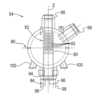
[0013] FIG. 3 is a front view of an economizer inlet mixing device for
use with the
economizer water recirculation system; and
[0014] FIG. 4 is a top view of the economizer inlet mixing device of
FIG. 3.
Detailed Description
[0015] Referring to FIG. 1, one exemplary embodiment of a boiler, in
which an
economizer water recirculation system is employed, is designated generally by
the reference
number 10. In one embodiment, the boiler 10 is a supercritical pressure
boiler. Fuel is
combusted in the boiler 10, and chemical energy therein is converted into
thermal energy and
is used to heat a liquid within the boiler to produce a vapor that can be used
to drive a turbine
or the like, The liquid is hereinafter referred to as being water, and the
vapor is hereinafter
referred to as steam.
[0016] In the boiler 10, the fuel and an oxidant are introduced into a
furnace 12
having waterwalls 14. Upon combustion of the fuel, a flue gas 16 is generated
and is directed
to a superheater 20, through an economizer 22, and into a selective catalytic
reduction (SCR)
system 24 (hereinafter "SCR 24").
[0017] To produce the steam, which is designated by the reference
number 28,
feedwater is fed to the economizer 22 via an economizer water recirculation
system 30
= (hereinafter "recirculation system 30"). A water stream 34 from the
recirculation system 30 is
directed to the economizer 22. Heat is transferred from the flue gas 16 to the
water stream
passing through the economizer. A water stream 36 from the economizer 22 then
passes
through the waterwalls 14 before being directed as a stream 37 to the
superheater 20. A
3a
CA 02785170 2012-06-20
WO 2011/084243
PCT/US2010/057185
recirculation fluid flow 38 is taken from the stream 37 after passing through
the waterwalls
and is fed back to the recirculation system 30. In doing so, the temperature
of the water
entering the economizer 22 is increased in a controlled manner. This decreases
the
economizer heat absorption by reducing the temperature difference between the
flue gas and
the water in the economizer. The result is an increase in the temperature of
the flue gas 16
exiting the economizer 22.
[0018] Referring now to FIG. 2, the recirculation system 30 receives two
separate
streams, namely, the feedwater stream 40 and the recirculation fluid flow 38.
In receiving the
feedwater stream 40, the feedwater stream is fed through a startup water
stream, which is
received either from the outlet of a startup valve that supplies the feedwater
during conditions
of low feedwater flow or from the main feedwater valve. The water stream 34
exiting the
recirculation system 30 is directed to the economizer 22. As stated above, the
water stream 36
then exits the economizer.
[0019] A minimal flow of fluid from a warming line 44 between check valve
46 and
the boiler mixing chamber 48 keeps the piping at uniform temperatures.
[0020] As is shown, the recirculation system 30 comprises the
recirculation check
valve 46 through which the recirculation fluid flow 38 is received, a flow
control valve
arrangement 50 that receives the recirculation fluid flow 38, an economizer
inlet mixing
device 54 that receives feedwater flow and recirculation flow through the flow
control valve
arrangement 50, and a recirculation pump/valve arrangement 56 that receives an
outlet fluid
stream from the economizer inlet mixing device 54. The combined feedwater
stream 40 and
the startup stream are received into the recirculation system 30 via the
economizer inlet
mixing device 54
[0021] In the illustrated embodiment, the flow control valve arrangement
50
comprises a pneumatic- or motor-actuated temperature-controlled valve 60,
which can be
isolated using gate valves 62 located upstream and downstream thereof. The
pneumatic- or
motor-actuated temperature-controlled valve 60 and the adjacently positioned
gate valves 62
can be bypassed via a bypass line 64 with a bypass globe valve 65.
[0022] The fluid flow through the flow control valve arrangement 50 is
received into
the economizer inlet mixing device 54.
[0023] The fluid flow from the economizer inlet mixing device 54 is
received into the
recirculation pump/valve arrangement 56, which comprises one or more
recirculation pumps
70. Operation of the pump(s) 70 reduces the pressure of the fluid in the
economizer inlet
mixing device 54. The recirculation system 30 is not limited in this regard
however, as the
4
CA 02785170 2012-06-20
WO 2011/084243
PCT/US2010/057185
pressure in the economizer inlet mixing device 54 can be additionally reduced
by locating
additional pumps in series at the inlet of the economizer 22. In the
recirculation pump/valve
arrangement 56 shown, gate valves 71 isolate the flow of fluid into the pumps,
and stop-
check valves 73 prevent backflow through the pumps 70. The outlet stream of
the pumps 70
is the fluid stream 34. A bypass line 72 may be used to direct all or a
portion of the flow
around the recirculation pump/valve anangement 56. The bypass line 72 includes
a bypass
stop-check valve 74.
[0024] In combining the feedwater with the recirculated fluid from the
flow control
valve arrangement 50, the temperature of the fluid mixture entering the
economizer 22 is
controlled (increased). This decreases the economizer heat absorption by
reducing the
temperature difference between the flue gas and the water in the economizer
22. The result is
an increase in the economizer exit gas temperature (flue gas 16). The
recirculation system 30
thereby allows for maintaining a higher economizer exit gas temperature (i.e.,
the
temperature at the economizer outlet) as compared to prior art boilers, at
reduced boiler steam
flows. By controlling the quantity of recirculation fluid flow 38, the gas
temperatures
entering the SCR 24 are increased during low load operation. This enables the
SCR 24 to
remain in service at lower loads. Moreover, the recirculation system 30 can be
retrofit to
existing supercritical boilers, thereby allowing for more predictable SCR
inlet gas
temperature stratification and less SCR mixing equipment as compared to prior
art gas bypass
systems.
[0025] Referring now to FIGS. 3 and 4, the economizer inlet mixing device
54
comprises a housing 80 in which a sparger assembly 82 is mounted. The upper
section of the
sparger assembly 82 receives the recirculation fluid flow 38 from the flow
control valve
arrangement 50 through an inlet 86. Because the recirculation fluid flow 38 is
from the
stream 37 from the waterwalls 14 and the outer waterwalls to the superheater
20, the fluid in
this stream is at very high temperature during operation of the boiler 11.
[0026] When directed into the sparger assembly 82, the recirculation
fluid is sprayed
or otherwise dispersed within the housing 80 to mix with the incoming
feedwater. The
sparger assembly comprises a cylindrical member 90 having a plurality of
holes, slits, or
other openings 92 therein. The pressure head of the flow through the inlet 86,
which may be
substantial, sparges the fluid from the inside of the cylindrical member 90
through the
openings 92 to the area outside of the cylindrical member and enclosed by the
inner wall of
the housing 80.
CA 02785170 2015-04-16
78396-02
[0027] The feedwater stream 40 (combined with the startup water stream)
is also
received into the housing 80 via two or more feedwater inlets 88.
[0028] The lower section of sparger assembly 82 is a pump-protection
strainer for the
mixed fluid, which discharges into an outlet 94 comprising a downcomer nozzle
below which
a wave breaker assembly 84 is mounted. The wave breaker assembly 84 comprises
a plurality
of baffles 96 longitudinally arranged in a conduit 98. The baffles 96 are
sized and positioned
to destroy any fluid-side propagation waves and to direct the flow from the
housing 80 in
lines of flow parallel to the direction in which the conduit 98 extends,
thereby eliminating the
potential for unstable vibrations caused by close proximity cavitation. From
the wave breaker
assembly 84, the fluid is directed to the recirculation pump/valve arrangement
56.
[0029] As can be seen in FIG. 3, support legs 100 are mounted on the
outside of the
housing 80 to allow the economizer inlet mixing device 54 to be constrained.
Although four
legs are shown as supporting the housing 80, it should be understood that any
number of legs
that can suitably constrain the housing can be employed. As can be seen in
FIG. 4, the
feedwater inlets 88 are offset from a central axis Z extending vertically
through the housing
80 and are arranged such that flow streams through each intersect each other
for mixing.
[0030] By flowing the feedwater and the hot fluid from the flow control
valve
arrangement 50 through the sparger assembly and the wave breaker assembly of
the
economizer inlet mixing device 54, periodic vibrations due to a close
proximity of pressure
pockets collapsing and large fluid temperature differences, are prevented or
at least
minimized.
[0031] Although the present disclosure has been shown and described
with respect to
the detailed embodiments thereof, it will be understood by those of skill in
the art that various
changes may be made and equivalents may be substituted for elements thereof
without
departing from the scope of as described herein. In addition, modifications
may be made to
adapt a particular situation or material to the teachings of the invention
without departing
from the essential scope thereof. Therefore, it is intended that the present
disclosure not be
limited to the particular embodiments disclosed in the above description, but
that the
invention will include all embodiments falling within the scope of the
appended claims.
6