Note: Descriptions are shown in the official language in which they were submitted.
CA 02785437 2012-06-21
WO 2011/090756 PCT/US2010/062415
1
SPRINGS AND METHODS OF FORMING SAME
FIELD OF THE DISCLOSURE
This disclosure, in general, relates to springs, seals using such springs, and
methods
for forming such springs and seals.
BACKGROUND
Springs are used in a variety of industries to apply force in a particular
direction. In
particular, springs are used in seal applications to energize sealing material
into contact with a
surface and to promote formation of a seal between parts moving relative to
one another.
Springs useful in such seals can include helically round ribbon or folded flat
stock springs.
Folded flat stock springs are conventionally formed through stamping
processes. Flat
stock is conventionally supplied to a stamping machine that stamps a pattern
into the flat
stock and the patterned flat stock is subsequently folded to form the flat
stock spring. Such
springs can be incorporated into seals, such as annular seals or face seals.
However, the conventional stamping process introduces stress into the stamped
form,
particularly around the edges. Further, stamping results in a considerable
amount of waste
material and can form burrs and undesirable sharp protrusions on edges of a
spring. In
addition, such conventional stamping processes are not conducive to continuous
processing of
metal components and as such, tend to be performed in batch processes,
reducing the
efficiency of production.
As such, an improved spring and method for forming such springs would be
desirable.
BRIEF DESCRIPTION OF THE DRAWINGS
The present disclosure may be better understood, and its numerous features and
advantages made apparent to those skilled in the art by referencing the
accompanying
drawings.
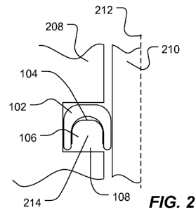
FIG. 1 includes a perspective-view illustration of an exemplary seal.
FIG. 2 includes a cross-sectional view illustration of an exemplary seal, such
as the
exemplary seal illustrated in FIG. 1.
FIG. 3 includes a perspective-view illustration of an exemplary seal.
CA 02785437 2012-06-21
WO 2011/090756 PCT/US2010/062415
2
FIG. 4 includes a cross-sectional view illustration of an exemplary seal, such
as the
exemplary seal illustrated in FIG. 3.
FIG. 5, FIG. 6, FIG. 7, and FIG. 8 include illustrations of exemplary spring
patterns.
FIG. 9 includes an illustration of an exemplary laser cutting apparatus.
FIG. 10 includes an illustration of an exemplary system for manufacturing
springs.
FIG. 11, FIG. 12, and FIG. 13 include illustrations of cut edges of flat stock
material.
The use of the same reference symbols in different drawings indicates similar
or
identical items.
DESCRIPTION OF THE PREFERRED EMBODIMENT(S)
In a particular embodiment, a method of forming a spring includes dispensing a
ribbon of flat stock or sheet metal, cutting the flat stock or sheet metal
with a laser cutting
apparatus to form a plurality of spring elements distributed longitudinally
along the ribbon,
and folding the laser cut ribbon to form a spring. In an example, folding
includes folding to
form a longitudinal crease. In particular, such folding can form the ribbon or
flat stock into a
spring having a V-shaped or U-shaped cross section. Further, the spring
elements can include
tines, loops, or other structures that, when in position, push against another
object such as a
seal jacket. In a particular example, the spring can be inserted into the
cavity of a seal jacket,
such as an annular jacket, to form a seal.
In another embodiment, a method of forming a spring includes dispensing a tube
and
cutting the tube with a laser to form a spring. In an example, the laser
cutting results in a
spiral cut around the circumference of the tube. The tube can be rotated
during cutting. The
laser cut tube can be inserted into the cavity of a seal jacket.
In an embodiment illustrated in FIG. 1, the seal 100 includes a jacket 102 and
a spring
104 disposed within a cavity 106 of the jacket 102. As illustrated, the seal
100 is an annular
seal which can, for example, be disposed in an annular space around an axis.
As illustrated in
FIG. 2, the seal 100 can be disposed within an annular region 214 of a
component 208. The
spring 104 energizes the jacket 102 to contact a rotating component 210 that
rotates around an
axis 212. The sidewalls 110 of the spring 104 energize the sidewalls 112 of
the jacket 102 to
maintain contact with the moving and static components (210 and 208).
The jacket 102 can be formed of a polymeric material or a composite material
including a polymeric material. The polymeric material can include a
thermoplastic material,
CA 02785437 2012-06-21
WO 2011/090756 PCT/US2010/062415
3
such as an engineering or high performance thermoplastic polymer. For example,
the
thermoplastic material can include a polymer, such as a polyketone,
polyaramid, a
thermoplastic polyimide, a polyetherimide, a polyphenylene sulfide, a
polyethersulfone, a
polysulfone, a polyphenylene sulfone, a polyamideimide, ultra high molecular
weight
polyethylene, a thermoplastic fluoropolymer, a polyamide, a polybenzimidazole,
a liquid
crystal polymer, or any combination thereof. In an example, the thermoplastic
material
includes a polyketone, a polyaramid, a polyimide, a polyetherimide, a
polyamideimide, a
polyphenylene sulfide, a polyphenylene sulfone, a fluoropolymer, a
polybenzimidazole, a
derivation thereof, or any combination thereof. In a particular example, the
thermoplastic
material includes a polymer, such as a polyketone, a thermoplastic polyimide,
a
polyetherimide, a polyphenylene sulfide, a polyether sulfone, a polysulfone, a
polyamideimide, a derivative thereof, or any combination thereof. In a further
example, the
thermoplastic material includes polyketone, such as polyether ether ketone
(PEEK), polyether
ketone, polyether ketone ketone, polyether ketone ether ketone ketone, a
derivative thereof, or
any combination thereof. An example thermoplastic fluoropolymer includes
fluorinated
ethylene propylene (FEP), polytetrafluoroethylene (PTFE), polyvinylidene
fluoride (PVDF),
perfluoroalkoxy (PFA), a terpolymer of tetrafluoroethylene,
hexafluoropropylene, and
vinylidene fluoride (THV), polychlorotrifluoroethylene (PCTFE), ethylene
tetrafluoroethylene copolymer (ETFE), ethylene chlorotrifluoroethylene
copolymer (ECTFE),
), a copolymer of ethylene and fluorinated ethylene propylene (EFEP),
polyvinyl fluoride
(PVF), a terpolymer of tetrafluoroethylene, hexafluoropropylene, and ethylene
(HTE), or any
combination thereof. An exemplary liquid crystal polymer includes aromatic
polyester
polymers, such as those available under tradenames XYDAR (Amoco), VECTRA
(Hoechst Celanese), SUMIKOSUPERTM or EKONOLTM (Sumitomo Chemical), DuPont
HXTM or DuPont ZENITETM (E.I. DuPont de Nemours), RODRUNTM (Unitika),
GRANLARTM (Grandmont), or any combination thereof. In an additional example,
the
thermoplastic polymer can be ultra high molecular weight polyethylene.
The composite material can also include a filler, such as a solid lubricant, a
ceramic
or mineral filler, a polymer filler, a fiber filler, a metal particulate
filler, salts, or any
combination thereof. An exemplary solid lubricant includes
polytetrafluoroethylene,
molybdenum disulfide, tungsten disulfide, graphite, graphene, expanded
graphite, boron
nitride, talc, calcium fluoride, cerium fluoride, or any combination thereof.
An exemplary
ceramic or mineral includes alumina, silica, titanium dioxide, calcium
fluoride, boron nitride,
mica, Wollastonite, silicon carbide, silicon nitride, zirconia, carbon black,
pigments, or any
combination thereof. An exemplary polymer filler includes polyimide, liquid
crystal
polymers, polybenzimidazole, polytetrafluoroethylene, any of the thermoplastic
polymers
CA 02785437 2012-06-21
WO 2011/090756 PCT/US2010/062415
4
listed above, or any combination thereof. An exemplary fiber includes nylon
fibers, glass
fibers, carbon fibers, polyacrylonitrile fibers, polyaramid fibers,
polytetrafluoroethylene
fibers, basalt fibers, graphite fibers, ceramic fibers, or any combination
thereof. Exemplary
metals include bronze, copper, stainless steel, or any combination thereof. An
exemplary salt
includes a sulfate, a sulfide, a phosphate, or any combination thereof.
In an embodiment, the composite material can be an elastic material. A Young's
modulus can be a measure of the stiffness of the composite material and can be
determined
from the slope of a stress-strain curve during a tensile test on a sample of
the material. The
composite material can have a Young's modulus of at least about 0.5 GPa, such
as at least
about 1.0 GPa, at least about 3.0 GPa, or even at least about 5.0 GPa.
In an embodiment, the composite material can have a relatively low coefficient
of
friction. For example, the coefficient of friction of the composite material
can be not greater
than about 0.4, such as not greater than about 0.2, or even not greater than
about 0.15.
In another embodiment, the composite material can have a relatively high
elongation.
For example, the composite material can have an elongation of at least about
20%, such as at
least about 40%, or even at least about 50%.
Returning to FIG. 1, the spring 104 is formed of a laser cut flat stock
material that is
folded or bent to form the spring. An exemplary flat stock material is formed
of a metal or
metal alloy. The metal alloy can be a stainless steel; a copper alloy such as
beryllium copper
and copper-chromium-zinc alloy; a nickel alloy such as Hastelloy, Ni220,
Phynox, or Elgiloy;
or the like; or a combination thereof. Additionally, the spring can be plated
with a plating
metal, such as gold, tin, nickel, silver or any combination thereof.
The flat stock can have a thickness of not greater than 10 mils, such as not
greater
than 5 mils, or even not greater than 3 mils. In particular, the thickness of
the flat stock can
be in a range of 1 mil to 5 mils, such as 1 mil to 3 mils, or even a range of
1.5 mils to 2.5 mils.
In another example, the thickness can be in a range of 2 mils to 10 mils, such
as 3 mils to 10
mils, or 5 mils to 10 mils. In an example, the flat stock is provided in the
form of a ribbon
having a width not greater than 10 inches, such as not greater than 5 inches.
For example, the
ribbon can have a width in a range of 0.5 inches to 10 inches, such as in a
range of 0.5 inches
to 5 inches, or even a range of 0.5 inches to 3 inches. Further, a ratio of
the width of a spring
work piece formed from the ribbon to the width of the ribbon can be at least
0.9, such as at
least 0.95. In a particular example, the ratio of the width of the cut spring
work piece to the
width of the ribbon is approximately 1Ø
CA 02785437 2012-06-21
WO 2011/090756 PCT/US2010/062415
The jacket 102 defines an annular cavity 106 in which the spring 104 is
disposed. As
illustrated in FIG. 1, the cavity 106 which extends within the jacket 102 is
accessible via an
opening 108. As illustrated, the opening 108 is positioned on an axial side of
the seal 100.
An axial side is a side through which a line parallel to an axis of the seal
100 extends.
5 Alternatively, the opening 108 can be formed on a radial side of the seal
100. A radial side is
a side through which a radial line extending from the axis of the seal 100
extends. In an
example, the opening 108 is disposed on a radially inward surface of the seal
100, facing the
axis. Alternatively, the opening 108 is disposed on a radial outward surface
of the seal 100,
further from the axis than the radially inward surface.
For example, FIG. 3 includes an illustration of an exemplary seal 300, which
includes
a jacket 302 and a spring 304 disposed in a cavity 306 of the jacket 302. As
illustrated, the
opening 308 to the cavity 306 is disposed on a radially inward surface of the
seal 300. Such a
seal configuration is particularly useful as a face seal as illustrated in
FIG. 4. For example,
the seal 300 can be disposed in an annular space of a block 408 around an axis
412. A
rotating component 410 that rotates about the axis 412 can be disposed to
contact the seal
300. The spring 302 energizes sidewalls of the jacket 302 against a face of
the rotating
component 410.
To form the spring, a spring pattern is laser cut into a flat stock ribbon.
The spring
pattern includes a plurality of spring elements distributed longitudinally
along the ribbon.
Longitudinal refers to a direction parallel to the longest dimension of the
ribbon or tube and
latitudinal refers to cross dimension of the ribbon or tube extending
perpendicular to the
longitudinal dimension and thickness. Generally, the latitudinal dimension is
the second
longest orthogonal dimension of the ribbon or tube. In an example, the spring
elements
include tines, loops, or any combination thereof, which can extend
latitudinally and can be
connected to a spring body.
In an example illustrated in FIG. 5, a spring 500 includes a laser cut pattern
that forms
loops 504 which extend latitudinally across the width of a flat stock ribbon.
Following
patterning, the spring 500 can be bent along longitudinal creases 502 to form
a U-shaped
spring. Alternatively, the spring 500 can be bent along one or more creases
extending
longitudinally. For example, the spring 500 can be bent along a single
longitudinal crease to
form a V-shape. Alternatively, the spring 500 can be folded along three or
more longitudinal
creases to form more complex structures when viewed in cross-section.
In another example illustrated in FIG. 6, a spring 600 can include loops 604
having a
thinner cross-dimension than the pattern illustrated in FIG. 5. Once formed,
the pattern 600
CA 02785437 2012-06-21
WO 2011/090756 PCT/US2010/062415
6
forms loops 604. Folds can be applied along a crease lines 602 extending
longitudinally
along the pattern to form a spring.
In an alternative example illustrated in FIG. 7, a pattern 700 can include
tines 704
extending from a body 706 in a latitudinal direction. The pattern 700 can be
folded along
longitudinal crease lines 702 to form a spring.
In an additional example illustrated in FIG. 8, a pattern 800 can be
implemented with
continuous strips 804 connected by cross-pieces 806. Such a pattern 800 can be
folded along
longitudinal crease lines 802 to form a spring such as a U-shaped or V-shaped
spring.
Alternatively, the spring can be formed of a laser cut tube. The tube can be
formed of
the metal or metal alloys described above in relation to the flat stock. In an
example, the
resulting spring can have a spiral configuration. In another example, a
plurality of spring
elements distributed along the longitudinal length of the spring can be cut
from the tube. For
example, elements similar to the elements described above in relation to FIG.
5, FIG. 6, FIG.
7, and FIG. 8 can be cut from the tube to form a spring. The tube can have a
thickness of not
greater than 10 mils, such as not greater than 5 mils, or even not greater
than 3 mils. In
particular, the thickness of the flat stock can be in a range of 1 mil to 5
mils, such as 1 mil to 3
mils, or even a range of 1.5 mils to 2.5 mils. In another example, the
thickness can be in a
range of 2 mils to 10 mils, such as 3 mils to 10 mils, or 5 mils to 10 mils.
The diameter (OD)
of the tube can be in a range of 50 mils to 10 inches, such as a range of 50
mils to 5 inches, a
range of 50 mils to 2 inches, a range of 50 mils to 1000 mils, or a range of
50 mils to 500
mils.
In an exemplary method, a ribbon or tube is dispensed or fed into a laser
cutting
apparatus. The laser cutting apparatus forms a pattern, such as the patterns
illustrated in FIG.
5, FIG. 6, FIG. 7, or FIG. 8, into the ribbon or tube, or a helical or spiral
pattern into the tube.
The resulting spring work piece is continuously fed into a die. The die
imparts folds along
crease lines into the spring work piece. Subsequently, the work piece can be
inserted into a
cavity of a jacket to form a seal. In particular, the seal can be an annular
seal and the cavity
can extend annularly within a jacket.
FIG. 9 includes an illustration of an exemplary cutting device 900, which
feeds a
ribbon 902 into a feed block 910. A laser head 906 is attached to a
positioning system 904.
As the ribbon 902 is fed into the feed block 910, the positioning system 904
manipulates the
position of the laser at 910 which cuts the ribbon 902 to form a pattern of
the spring work
piece. In particular, the pattern includes a plurality of spring elements such
as tines, loops,
CA 02785437 2012-06-21
WO 2011/090756 PCT/US2010/062415
7
cross-pieces, or any combination thereof, that extend latitudinally across the
ribbon 902 and
are distributed longitudinally along the length of the ribbon 902.
In a particular example, the cutting device includes the laser head 906 and a
laser core
(not illustrated). The laser core can be fiber laser. A fiber laser is a laser
in which the active
gain medium is an optical fiber doped with rare-earth elements, such as
erbium, ytterbium,
neodymium, dysprosium, praseodymium, and thulium. Once the laser radiation is
generated
in the fiber active gain medium, the radiation can be guided to the target
ribbon using
additional optical fibers, guides, reflectors, or lenses.
Such cutting devices 900 are particularly useful in a system to continuously
form a
spring work piece. As illustrated in FIG. 10, a system 1000 feeds a ribbon
1008 into a laser
cutting device 1002 to produce a spring work piece 1010. Alternatively, a tube
can be fed to
the laser cutting device 1002. The laser cutting device 1002 cuts a pattern
into the ribbon
1008 or a tube to form the spring work piece 1010. The pattern can include a
plurality of
spring elements that extend latitudinally across the ribbon 1008 and are
distributed
longitudinally along the spring work piece 1010. In particular, the spring
elements are
connected forming contiguous spring work pieces. For example, the spring
elements can be
loops formed as a serpentine pattern. In another example, the spring elements
can be formed
as tines extending from a spring body. In a further example, the spring
elements can be
connected on edges of the ribbon.
In an example, the spring work piece can be dispensed from the laser cutting
device
1002 as a single continuous strip. In an alternative example, the laser
cutting device can
further cut the spring work piece latitudinally across the ribbon to form
separate spring work
pieces from the contiguous pattern.
A feeder 1014 guides the spring work piece into a die 1004. In an example,
waste
material is removed from the spring work piece 1010 before it is guided into
the die 1004.
The die 1004 folds the spring work piece along longitudinal creases to form
the folded spring
work piece 1012. When the spring work piece 1010 is in the form of a
continuous strip, the
die 1004 can be configured to continuously form the creases as the strip is
fed into the die
1004. The die 1004 can include a cutter to cut the strip, either before
folding or after folding,
to form individual folded spring work pieces 1012.
Alternatively, when the spring work piece 1010 is in the form of separate
spring work
pieces, the feeder 1014 can be configured to feed each separate spring work
piece into the die
1004. The die 1004 can include sensors and mechanisms to position the spring
work piece
CA 02785437 2012-06-21
WO 2011/090756 PCT/US2010/062415
8
1010 and when the spring work piece 1010 is in position, fold the spring work
piece 1010,
such as in a single step.
The folded spring work piece 1012 can be supplied continuously or in a batch
process
to a device 1006 for inserting the folded spring work piece into the cavity of
a seal jacket. In
a particular example, the folded spring work piece 1012 is fed continuously
into a device
1006 that further bends the spring work piece to form a circular form to be
inserted into a
cavity of an annular seal.
In a particular example, the laser cutting apparatus 1002 is a fiber laser
having an
optical fiber active gain medium. Such a fiber laser is contrasted with lasers
that include
active gain media in the form of a gas or solid core. Each of the fiber laser
and the other
lasers can transfer the emitted pulse by additional optical fibers. However,
the presence of
optical fibers does not necessarily imply that the laser is a fiber laser.
Applicants discovered that fiber lasers overcome difficulties associated with
laser
cutting of spring patterns in thin flat stock materials presented by other
laser devices. In
particular, Applicants discovered that such fiber lasers permit the formation
of spring patterns
in flat stock having a thickness not greater than 10 mils, such as a thickness
in a range of 1
mil to 8 mils, or a range of 1 mil to 3 mils. Alternative laser technologies
tended to produce
imprecise cuts and overheating which led to warping of spring elements.
Imprecise cuts or
overheating can lead to inconsistencies within a spring, that leads to
variable wear or poor
sealing. Further, fiber lasers permit the precise cutting of thin flat stock
which allows the
formation of spring elements that extend latitudinally across a large portion
of the ribbon. For
example, the spring elements can extend at least 90% across the latitudinal
width of the
ribbon, such as at least 95%, or even approximately 100% across the
latitudinal width of the
ribbon. As such, with such precise cutting, a reduction in waste material can
be achieved.
Further, such fiber lasers reduce strain and stress introduced at the edge of
a patterned
work piece. As illustrated in FIG. 11, a laser cut edge in an Elgiloy material
provides a
relatively smooth cut having only shallow undulations spaced apart at greater
than 10
micrometers. In contrast, FIG. 12 includes an illustration of an exemplary
stamp formed edge
exhibiting a separation 1202 between surfaces 1204 and 1206, which have
distinct patterns.
The surface 1204 is indicative of plastic deformation formed by compressive
forces followed
by a fracture resulting in the surface 1206. An intermediate separation 1202
forms between
the two surfaces 1204 and 1206.
CA 02785437 2012-06-21
WO 2011/090756 PCT/US2010/062415
9
Edging, as illustrated in FIG. 13, produces a similar result in which two
distinct
surfaces 1302 and 1304 illustrate deformation followed by a fracture. Although
the stress
represented by horizontal striations 1306 between the two surfaces 1302 and
1304 are less
prominent than those illustrated in FIG. 12, edging and stamping clearly
introduce stress at an
edge of an object that is not found in the laser cut sample. In contrast to
the stamped and
edged surfaces, the laser cut surfaces are free of a fracture surface and are
free of striations or
separations extending parallel to a surface of the cut ribbon.
It is believe that stamping, particularly for metal thicknesses in a range of
3 mils to 8
mils causes a hardening of the spring material not found when laser cutting.
Such hardening
can result in early fatigue in spring configurations.
Example
Fatigue tests are performed on samples of U-shaped springs. The U-shaped
springs
are formed of flat stock material, patterned either by cutting with a fiber
laser device or by
stamping. The patterned flat stock material is folded into the U-shaped
spring. The resulting
U-shaped spring is a cantilever finger spring design, similar to the spring of
the Omniseal
400A, available from Saint-Gobain. Sample springs are prepared from 304
Stainless Steel
having a thickness of 2 mils and from 301 Stainless Steel having a thickness
of 5 mils.
Testing is performed by cycling the fingers of the spring between a flexed
position
and a relaxed position. At the ends of the fingers, the flexed position is
inward approximately
20 mils to 30 mils toward a center of the spring relative to the relaxed
position. The samples
are cycled until failure through fatigue or for one million cycles.
As illustrated in Table 1, the 2-mil stainless steel samples patterned by
either laser
cutting or stamping survived flexing for one million cycles. For the 5 mil
samples, the laser
cut sample cycled 200,000 cycles, twice as long as the stamped cycles.
CA 02785437 2012-06-21
WO 2011/090756 PCT/US2010/062415
TABLE 1. Flex Testing of Stainless Steel Samples
Sample Material Method Thickness (mils) Cycles-to-
Failure
1 304 SST Laser 2 >1M
2 304 SST Stamp 2 >1M
3 301 SST Laser 5 200,000
4 301 SST Stamp 5 100,000
In a first aspect, a seal includes a polymeric jacket defining a seal surface
and an
inner cavity extending within the polymeric jacket along a length of the
polymeric jacket and
a spring extending within the inner cavity and including a plurality of laser
cut spring
5 elements.
In an example of the first aspect, an edge of the spring is free of a fracture
surface. In
another example, an edge of the spring is free of a separation.
In a further example, the polymer jacket includes a polymeric material
selected from
the group consisting of polyketone, polyaramid, a thermoplastic polyimide, a
polyetherimide,
10 a polyphenylene sulfide, a polyethersulfone, a polysulfone, a polyphenylene
sulfone, a
polyamideimide, ultra high molecular weight polyethylene, a thermoplastic
fluoropolymer, a
polyamide, a polybenzimidazole, a liquid crystal polymer, or any combination
thereof. In
another example, the polymer jacket further includes a filler selected from
the group
consisting of a solid lubricant, a ceramic or mineral filler, a polymer
filler, a fiber filler, a
metal particulate filler, salts, or any combination thereof.
In an additional example, the polymer jacket has a coefficient of friction of
not
greater than about 0.4, such as not greater than about 0.2.
In another example, the polymer jacket has a Young's modulus of at least about
0.5
GPa, such as at least about 1.0 GPa. The polymer jacket can have an elongation
of at least
about 20%, such as at least about 40%.
In an example, the spring is formed of a metal alloy selected from the group
consisting of stainless steel, a copper alloy, a nickel alloy, or any
combination thereof. In
CA 02785437 2012-06-21
WO 2011/090756 PCT/US2010/062415
11
another example, the spring is formed of a sheet material having a thickness
not greater than
mils, such as not greater than 5 mils, or not greater than 3 mils.
In a particular example, the seal is an annular seal or a face seal.
In a second aspect, a seal includes an annular jacket comprising a polymeric
material
5 and defining an annular cavity extending within the annular jacket and a
spring extending
within the annular cavity, the spring comprising a folded sheet metal
including a plurality of
laser cut spring elements.
In an example of the second aspect, an edge of the spring is free of a
fracture surface.
In another example, an edge of the spring is free of a separation.
10 In a further example, the polymeric material is selected from the group
consisting of
polyketone, polyaramid, a thermoplastic polyimide, a polyetherimide, a
polyphenylene
sulfide, a polyethersulfone, a polysulfone, a polyphenylene sulfone, a
polyamideimide, ultra
high molecular weight polyethylene, a thermoplastic fluoropolymer, a
polyamide, a
polybenzimidazole, a liquid crystal polymer, or any combination thereof. In an
additional
example, the annular jacket further includes a filler selected from the group
consisting of a
solid lubricant, a ceramic or mineral filler, a polymer filler, a fiber
filler, a metal particulate
filler, salts, or any combination thereof.
In another example, the annular jacket has a coefficient of friction of not
greater than
about 0.4. Ina further example, the annular jacket has a Young's modulus of at
least about
0.5 GPa. In an additional example, the annular jacket has an elongation of at
least about 20%.
In a further example, the spring is formed of a metal alloy selected from the
group
consisting of stainless steel, a copper alloy, a nickel alloy, or any
combination thereof. In an
additional example, the spring is formed of a sheet material having a
thickness not greater
than 10 mils.
In a third aspect, a method of forming a seal includes dispensing a ribbon of
sheet
metal, laser cutting a plurality of spring elements distributed longitudinally
along the ribbon
to form a spring work piece, and folding the spring work piece to form a
spring.
In an example of the third aspect, laser cutting includes laser cutting with a
fiber
laser. In another example, laser cutting includes laser cutting the plurality
of spring elements
to extend latitudinally across the ribbon.
CA 02785437 2012-06-21
WO 2011/090756 PCT/US2010/062415
12
In an additional example, the plurality of spring elements extend to have a
ratio of the
width of a spring work piece formed from the ribbon to the width of the ribbon
of at least 0.9,
such as at least 0.95. In a particular example, the ratio is approximately
1Ø
In a further example, the spring work piece is a continuous piece and wherein
folding
the spring work piece includes continuously folding the spring work piece. In
another
example, laser cutting the ribbon to form separate spring work pieces.
In an additional example, folding the spring work piece includes positioning
the
spring work piece and folding the positioned spring work piece. In an example,
the method
further includes inserting the spring into a seal jacket.
In a fourth aspect, a method of forming a seal includes dispensing a ribbon of
sheet
metal having a thickness of not greater than 5 mils, forming with a fiber
laser device a
plurality of spring elements distributed along a length of the ribbon and
extending
latitudinally across the ribbon, cutting the laser cut ribbon with the laser
device to form a
spring work piece, and folding the spring work piece along a longitudinal
length of the
ribbon.
In an example of the fourth aspect, the plurality of spring elements extend to
have a
ratio of the width of a spring work piece formed from the ribbon to the width
of the ribbon of
at least 0.9.
In an additional example, folding the spring work piece includes positioning
the
spring work piece and folding the positioned spring work piece. In a further
example, the
method includes inserting the spring into a seal jacket.
In a fifth aspect, a machine includes a static component, a rotatable
component, and a
seal disposed between the static component and the rotatable component. The
seal includes a
polymeric jacket defining a seal surface and an inner cavity extending within
the polymeric
jacket along a length of the polymeric jacket and a spring extending within
the inner cavity
and including a plurality of laser cut spring elements.
In a sixth aspect, a method of forming a seal includes dispensing a tube,
laser cutting
the tube to form a spring work piece, and inserting the spring work piece into
a jacket to form
the seal.
CA 02785437 2012-06-21
WO 2011/090756 PCT/US2010/062415
13
In an example of the sixth aspect, laser cutting the tube include cutting a
spiral. In
another example, laser cutting the tube includes cutting a pattern of spring
elements
distributed longitudinally along the length of the tube.
In an additional example, the method further includes rotating the tube while
laser
cutting. In a further example, the tube includes a metal or metal alloy.
Note that not all of the activities described above in the general description
or the
examples are required, that a portion of a specific activity may not be
required, and that one
or more further activities may be performed in addition to those described.
Still further, the
order in which activities are listed are not necessarily the order in which
they are performed.
In the foregoing specification, the concepts have been described with
reference to
specific embodiments. However, one of ordinary skill in the art appreciates
that various
modifications and changes can be made without departing from the scope of the
invention as
set forth in the claims below. Accordingly, the specification and figures are
to be regarded in
an illustrative rather than a restrictive sense, and all such modifications
are intended to be
included within the scope of invention.
As used herein, the terms "comprises," "comprising," "includes," "including,"
"has,"
"having" or any other variation thereof, are intended to jacket a non-
exclusive inclusion. For
example, a process, method, article, or apparatus that comprises a list of
features is not
necessarily limited only to those features but may include other features not
expressly listed
or inherent to such process, method, article, or apparatus. Further, unless
expressly stated to
the contrary, "or" refers to an inclusive-or and not to an exclusive-or. For
example, a
condition A or B is satisfied by any one of the following: A is true (or
present) and B is false
(or not present), A is false (or not present) and B is true (or present), and
both A and B are
true (or present).
Also, the use of "a" or "an" are employed to describe elements and components
described herein. This is done merely for convenience and to give a general
sense of the
scope of the invention. This description should be read to include one or at
least one and the
singular also includes the plural unless it is obvious that it is meant
otherwise.
Benefits, other advantages, and solutions to problems have been described
above with
regard to specific embodiments. However, the benefits, advantages, solutions
to problems,
and any feature(s) that may cause any benefit, advantage, or solution to occur
or become more
pronounced are not to be construed as a critical, required, or essential
feature of any or all the
claims.
CA 02785437 2012-06-21
WO 2011/090756 PCT/US2010/062415
14
After reading the specification, skilled artisans will appreciate that certain
features
are, for clarity, described herein in the context of separate embodiments, may
also be
provided in combination in a single embodiment. Conversely, various features
that are, for
brevity, described in the context of a single embodiment, may also be provided
separately or
in any subcombination. Further, references to values stated in ranges include
each and every
value within that range.