Note: Descriptions are shown in the official language in which they were submitted.
CA 02785871 2012-08-08
-1-
Title: METHOD AND APPARATUS FOR STIMULATING HEAVY
OIL PRODUCTION
This is a division of Canadian Patent Application No. 2,633,061 filed
February 23, 2000.
FIELD OF THE INVENTION
This invention relates to the extraction of hydrocarbons such as heavy
oil and bitumen. In particular this invention relates to reducing the
viscosity
of hydrocarbons such as heavy oil in situ to permit the heavy oil to flow more
readily and thus to improve the recovery thereof.
BACKGROUND OF THE INVENTION
Heavy oils refer to crude oils which have high specific gravity and
viscosity and are therefore difficult to extract commercially because they do
not readily flow. Heavy oils are found, for example, in the tar sand deposits
in Alberta, Canada. Typically these heavy oils will have viscosities greater
than 1000 centiPoise or specific gravities greater than .934 at 60 F (i.e.
less
than 20 API). There has long been sought a means to accelerate the
heavy oil production process by permitting the oil to flow more readily
thereby increasing the rate of return on capital and decreasing the financial
risk of such heavy oil production projects.
One thermal extraction technique, called fireflood, is generally
uneconomic due to very severe operating problems including corrosion,
scale precipitation and explosion hazards after breakthrough, not to mention
the difficulty in controlling the process and the production of plugging
deposits such as coke.
Another prior approach that has had some merit is to use steam in a
thermal stimulation for improving heavy oil extraction. Steam raises the
temperature of the oil and thereby reduces its viscosity and allows it to flow
CA 02785871 2012-08-08
-2-
more easily. Steam stimulation is subject to a number of problems,
including heat losses during injection, clay swelling problems, thief zones,
emulsions, capillary surface tension effects and lack of confinement for
shallower zones. Further, injecting steam creates water (condensate) in the
formation which is much less viscous than oil and which will therefore be
preferentially produced due to relative permeability effects. Preferential
production of water perversely makes the oil production or recovery more
difficult.
An additional problem, which has become more important recently,
is that most thermal recovery processes such as steam require large
amounts of methane gas to be burned to provide the energy to vaporize the
water above grade. This can lead to the emission of enormous amounts of
greenhouse gases such as carbon dioxide. For example a 100,000 bbl
oil/day heavy oil facility requires 200,000 - 300,000 bbl water /day to be
converted into steam at 200 C. Thus, for a methane gas burner system, to
recover 100,000bbl oil/day requires producing more than 12 million pounds
per day of carbon dioxide emissions. The two main traditional approaches
used in steam recovery systems have been "huff and puff' (i.e., cyclic
steaming) and steam floods. Recently, however, steam assisted gravity
drainage (SAGD) has become popular.
SAGD begins with the formation of a steam chamber in the formation.
The steam is injected into the chamber and transfers heat to the surface of
the chamber thereby mobilizing oil at the chamber surface. The heated oil
flows down the walls of the chamber under the influence of gravity and
drains into the producing well, thereby increasing the size of the chamber.
The advantage of SAGD is that the countercurrent flow of steam upwards
into the reservoir and oil down and out of the reservoir is relatively
efficient,
thus the heavy oil production rates are high enough to provide favourable
economics in some situations.
There are many possible SAGD geometries including single well
(injection and production from the same well) and dual or multiple well. The
CA 02785871 2012-08-08
-3-
wells may be either horizontal or vertical. Generally horizontal wells are
favoured by producers because they offer a longer exposure to the pay zone
and thereby offer increased production rates for highly viscous oils.
Single well SAGD offers the least capital cost, but heat losses due to
countercurrent flow of steam into and oil out of the wellbore are severe.
Quite simply, as the hot steam going into the well passes the cold oil coming
out of the well and the steam loses heat to the oil. For example, at an
injection pressure of 1000 psig and 285 C, the enthalpy of the steam is 1192
btu/Ib and the enthalpy of the water is 542 btu/Ib. Due to countercurrent
heat exchange the produced fluids (water and oil) are at the same
temperature as the injected steam. For typical injection conditions, the
steam quality is 80% (i.e., 80% vapour and 20% liquid). Thus, the maximum
heat delivered to the formation is only the latent heat of vaporization (i.e.
about 50% of the total heat input). With additional heat losses through the
well casing, the net heat delivery to the formation is quite low and thus this
process is inefficient.
There have also been in the past suggestions to use cold solvent
vapour to lower the viscosity of the heavy oil in situ. This was first
proposed
by Nenniger' (1979). This idea has shown much promise for production of
heavy oil with minimal environmental impact, primarily because such a
process does not require heating large volumes of steam nor huge amounts
of fresh water suitable for steam generation. Energy requirements for
solvent extraction are expected to be less than 4% of those required for
steam extraction. Insitu recovery has minimal environmental impact
compared to surface mining techniques.
The physics of cold solvent stimulation are not fully understood. The
measured solvent diffusion rates are typically 100 - 1000 times higher than
I Ncunigcr, 1:.H., Hydrocarbon Rccovcry, Canadian Patent 1,059,-132
i
CA 02785871 2012-08-08
-4-
predicted by theory2,3. A key economic requirement is efficient recovery of
the solvent, so light gases such as ethane and propane which can be
recovered by pressure blowdown are generally preferred. A recent study
has reported the ratio of ethane solvent loss to bitumen produced, was as
low as seven percent (wt/wt). However, the calculated production rates for
solvent extraction are marginal for commercial application and to date there
has never been a successful commercial pilot.
In a bench testa warm solvent (propane) was injected into a sample
of warmed heavy oil. This experiment showed that if the solvent
temperature was raised and the heavy oil temperature was also raised to the
same temperature (ie. Isothermal conditions) production rates could be
increased about 20 fold simply by increasing the temperature from 20 C to
90 C.
This observation led to the development of the Vapex process4 which
proposes to combine solvent with steam or hot water heated above grade
to provide downhole heat. Because of the water/steam this process suffers
from all the problems mentioned above (countercurrent heat exchange,
formation damage problems with clays, emulsions, capillary pressure, water
treatment, water supply, reduced oil relative permeability due to high water
saturations and the like).
A key requirement for both steam assisted gravity drainage and
solvent assisted gravity drainage is the formation of a steam or solvent
chamber in the reservoir. The chamber allows efficient countercurrent flow
of solvent vapour (or steam) upwards and flow of the heavy crude
downwards along the walls of the chamber. The predicted oil drainage rate
2 Dunn, S.G.; 1:.H. Ncuniger, V.S.V. Rajah, A Study of Bitumen Rccovcrv by
Gravity Drainage
Using Low Temperature Solublc Gas Inicction,'11c Canadian Journal of Chemical
Lnginccring, Vol
67, December 1989.
'; Lim, ct al, Three dimensional Scaled Physical Modelling of Solvent Vapour
Extraction of Cold Lake Bitumen, JCVI', April 1996, Page 37
1 See Table I and Figure 7 of Butler et al, A New Process for Recovering Heavy
Oils using Hot
Water and Hydrocarbon Vapours, JCP"I' Jan 1991, pg 100
CA 02785871 2012-08-08
-5-
is proportional to the square root of the height of the chamber (reference 4).
Thus the oil production rates are predicted to be very small initially and
then
grow with time until the roof of the chamber encounters a boundary such as
an impermeable shale.
This has been confirmed by lab tests which have shown that the
maximum oil production rates will not occur until a large solvent chamber is
formed. Unfortunately, in the field this means that peak oil production rates
do not occur until 3-4 years after the well is placed on production.
Thus, for solvent vapour extraction the peak oil production rates are
not typically achieved until perhaps three years after the capital costs of
the
well and the production facilities are incurred. The delayed production
response decreases the rate of return and increases the risk to the operator.
For example thief zones, etc, may not be identified until substantial costs
have been incurred (i.e. until after three years of solvent injection).
Thus, there is a need for the solvent chamber to be quickly
established. For example, the capital cost of drilling and completing a
horizontal well pair might be typically 1,800,000 dollars. The minimum
internal rate of return for a oil project is typically about 15%. Thus, the
opportunity cost of a one year delay in the peak production rate is 275K$.
If peak production is accelerated, so it occurs in the first year rather than
the
third, then the value added by early development of the solvent chamber
would be about 800K$ per well pair.
Thus, while the cold solvent vapour extraction process has great
advantages due to energy efficiency and minimal environmental damage,
it has never been successfully used. The primary reason is the cold solvent
vapour production rates are too low to be economic, particularly with a 3 -
4 year delay in achieving peak production rates. Another way of looking at
this issue, is to apply a discount to value of the produced oil if the
production
is delayed. At 15% rate of return, the 3 year delay gives a discount of 33%,
so the value of the oil production is reduced by 1/3. In other words, if the
market price of oil is 20$/bbl, the effective price the producer receives is
only
CA 02785871 2012-08-08
-6-
14$/bbl, due to the three year delay. Obviously this delayed startup has a
huge negative impact on the commercial feasibility of this environmentally
friendly technology.
What is desired is a way of stimulating production of heavy oil which
is energy efficient and yet is effective. In this respect it should not
require
the use of very high temperatures or high energy use rates as is the case
presently. Further, it would be preferable to avoid introduction of steam or
water into the formation which has negative effects on the production rates.
SUMMARY OF THE INVENTION
What is desired therefore, is a means to accelerate the oil production
rate by encouraging the rapid extraction of heavy oil or bitumen. According
to the present invention it is possible to accelerate the extraction process
by
the injection of heated solvent vapor into the reservoir in the absence of a
water/steam phase under certain predetermined conditions. As the solvent
condenses on the cold bitumen surface it supplies heat to the bitumen
interface, by releasing the latent heat of condensation, and greatly
accelerates the extraction without the problems associated with a liquid
water phase. Furthermore, by using solvent condensation as a heat transfer
mechanism, it is possible to significantly increase the proportion of solvent
in the bitumen solvent blend, thereby reducing blend viscosity, improving
drainage rates (production) and also achieving enhanced insitu upgrading
of the oil. Further according to the present invention countercurrent heat
exchange losses can be avoided by injecting the heated solvent from an
injection well and removing the produced fluid from an adjacent well which
is communication with the injection well. Thus, the present invention
contemplates establishing such a connection between the production and
injections wells prior to injecting a surface heated solvent vapor.
The present invention also takes into consideration various additional
factors such as the kinetics of extraction, hydraulics and heat transfer for
hot
gas delivery to the reservoir and recovery and recycle of solvent from the
CA 02785871 2012-08-08
-7-
produced fluid.
Accordingly, in the present invention, there is a provided a method
of recovering hydrocarbons from an underground formation comprising the
steps of:
selecting a solvent to inject into said underground formation wherein
said solvent can dissolve into at least some of said hydrocarbons within said
formation to reduce a viscosity of said hydrocarbons;
increasing a temperature of said hydrocarbons within said formation
to a temperature above a naturally occurring temperature to reduce the
viscosity of said at least some hydrocarbons and to increase the diffusivity
of said solvents into said hydrocarbons;
heating and pressurizing said solvent above grade and injecting the
same into said formation;
dissolving said injected solvent into said at least some hydrocarbons
in said formation at said higher diffusivity rate to mobilize the said at
least
some hydrocarbons within said formation by forming a hydrocarbon solvent
blend that can drain by gravity drainage; and
recovering said blend from said formation.
According to a further aspect of the present invention, there is
provided a method of recovering hydrocarbons from an underground
formation comprising the steps of:
selecting a solvent to inject into said underground formation wherein
said solvent can dissolve into at least some of said hydrocarbons within said
formation to reduce a viscosity of said hydrocarbons;
injecting said solvent into said formation at a controlled injection rate;
pressuring said formation by means of said controlled injection rate
to establish a condensing temperature within said formation for said injected
solvent;
dissolving said solvent within said hydrocarbons to form a reduced
viscosity blend having at least some solvent and some hydrocarbon;
controlling a solvent content of said blend by means of said formation
CA 021785871 2012-08-08
-8-
pressure control; and
recovering said blend from said formation.
Accordingly to yet another aspect of the present invention, there is
provided a method of recovering hydrocarbons from an underground
formation comprising the steps of:
selecting a solvent to inject into said underground formation wherein
said solvent can dissolve into at least some of said hydrocarbons within said
formation to reduce a viscosity of said hydrocarbons;
injecting said solvent into said formation at a controlled injection rate
to pressurize said formation;
controlling said pressure in said formation to establish a condensation
temperature for said solvent within said formation for said injected solvent
above ambient temperature;
condensing said solvent within said formation at said elevated
temperature to produce a blend having at least some solvent and some
hydrocarbon, wherein said blend has enough solvent content by reason of
said elevated pressure to drain by gravity drainage; and
recovering said draining blend from said formation.
According to another aspect of the present invention, there is
provided a method of recovering hydrocarbons from an underground
formation, said method comprising the steps of:
heating at least a portion of said formation to a temperature of
between 10 C and 70 C to increase the diffusivity of a solvent into said
heated hydrocarbons; and
diffusing said solvent into said hydrocarbons at said temperature to
form a mobile hydrocarbon solvent blend that drains through said formation;
and
extracting said mobile blend from said formation.
According to another aspect of the present invention, there is provide
a method of recovering hydrocarbons from an underground formation
comprising the steps of:
CA 02785871 2012-08-08
-9-
heating a formation to a temperature of between 20 C and 70 C to
reduce a viscosity of said hydrocarbons and to improve the diffusivity of said
hydrocarbon to a solvent; and
using said solvent in said formation to further reduce a viscosity of
said hydrocarbons through dilution to permit said hydrocarbons to drain
through said formation under the influence of gravity.
BRIEF DESCRIPTION OF THE DRAWINGS
Reference will now be made, by way of example only, to preferred
embodiments of the invention as illustrated in the accompanying drawings
and in which:
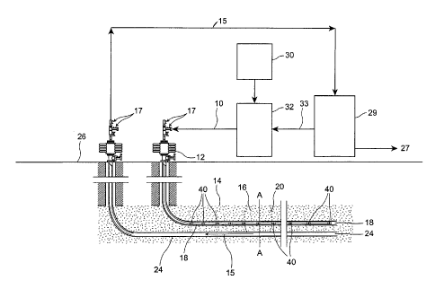
Figure 1 illustrates a process schematic of the present invention
showing formation of a solvent chamber;
Figure 2 illustrates the solvent chamber along section A-A of Figure
1 in more detail;
Figure 3 is a graph which shows a relationship between viscosity and
temperature for Athabasca bitumen, and the predicted relationship between
diffusion rate and temperature based on the Stokes- Einstein equation;
Figure 4 is a graph which illustrates a relationship between
temperature rise and volume of a theoretical reservoir heated at a constant
power rate of 1 megawatt;
Figure 5 is a graph which illustrates the vapour pressure of propane
solvent as a function of temperature;
Figure 6 is a graph which shows the latent heat of vaporization for
propane solvent as a function of temperature and the mass of propane
solvent vapour required to deliver one megawatt of heat (via latent heat of
condensation);
Figure 7 is a graph which shows the volumetric heat capacity of
vapour (via latent heat of condensation) as a function of temperature for
several solvents compared to steam;
Figure 8 is a graph which shows volume fraction of propane solvent
in produced fluid vs chamber temperature;
CA 02785871 2012-08-08
-10-
Figure 9 illustrates the bitumen- propane blend viscosity at 8C as a
function of propane solvent volume fraction and the favorable reduction in
viscosity at higher solvent ratios;
Figure 10 illustrates the propane solvent/bitumen blend viscosity as
a function of temperature; and
Figure 11 illustrates the extraction rate forthe heated propane solvent
vapour as a function of temperature and how the rate is limited by mass
transfer at temperatures below 40C and limited by heat transfer at
temperatures above 40C.
DETAILED DESCRIPTION OF THE PREFERRED EMBODIMENTS
Figure 1 shows a schematic of a process of stimulating heavy oil or
bitumen recovery according to the present invention. Generally, a hot solvent
10 is injected down an injection well 12 into a reservoir 14. The hot solvent
10
is most preferably a vapour, enters a solvent chamber 16 through a perforated
or slotted casing 18 or the like and flows out to condense on the cold bitumen
interface 20 to form a solvent/bitumen blend. The terms "bitumen" and "heavy
oil" are used interchangably in this specification and for the purposes of
this
invention means hydrocarbons which are recovered from naturally occurring
formations and which in their natural state are generally too viscous to
readily
flow into a production well. It will be appreciated that the present invention
is
most suitable for such formations as tar sands, but may also be used in other
formations.
The solvent bitumen blend 15 formed at the interface drains to the
bottom of the chamber 16 (shown at 22 in Figure 2), where it is removed via
a production well 24 and produced to surface 26. Valves 17 are located at
each well head. The bitumen is separated from the solvent at the surface 26
and the bitumen is sold 27. The separation at 29 of a solvent such as propane
from the bitumen, might involve a flash at a temperature above the critical
temperature of the solvent. The present invention comprehends that there
may be several stages of separation to maximize solvent recovery, which of
course will minimize solvent losses in the sold bitumen. It will be
appreciated
CA 02785871 2012-08-08
-11-
by those skilled in the art that some factors to consider in establishing
solvent
recovery are energy efficiency, reliability, and potential for fouling
problems
(i.e. deposition of asphaltenes). The recovered solvent 33 is then compressed,
and/or heated at 32 and then reinjected into the injection well 18. Additional
make up solvent is added as needed to replace the void volume created by
the extracted bitumen at 30. It may also be necessary to remove light gases
from solvent/bitumen blend which may have been co-produced from the
reservoir. These may also be used as fuel in re-heating the solvent.
The present invention comprehends a process in which a flow path has
already been established between an injection well and a production well.
This flow path could be established by any of a number of means including
downhole heaters or the like. The establishment of a flow connection is
desirable because this avoids countercurrent heat losses which might
otherwise occur. However, this step is not deemed essential if such
countercurrent heat losses can be mitigated through use of other strategies
such as insulated injection tubing or the like. It will be appreciated though
that
the most preferred form of the present invention is a flow through from an
injection well to a production or recovery well.
Figure 2 shows the solvent chamber 16 formed in this formation in
more detail. Also shown is a pressure containment layer, such as shale barrier
layer 21. The heated solvent vapour rises within the chamber 16 to condense
on the walls and roof 19 of the chamber 16. As the solvent condenses it
releases its latent heat of condensation thereby heating the bitumen interface
at the chamber surface. As the solvent dissolves and is mixed into the
bitumen the bitumen is upgraded by the precipitation out of asphaltenes. At
this stage the bitumen begins to flow as its viscosity has been lowered by two
effects namely, the heating effect from the latent heat of condensation and
the
dilution effect from being blended with the now liquid solvent. The bitumen-
solvent liquid blend 25 drains along the wall or down off the ceiling into the
sump 22. The liquid is then drained into the production well 24. As will be
more fully understood from the description below, the production of bitumen
solvent blend is preferably restricted to avoid solvent gas bypassing. This is
CA 02785871 2012-08-08
-12-
accomplished via a steam trap type control as currently practiced in SAGD
technology.
Figure 3 shows the viscosity of a typical Athabasca bitumen as a
function of temperature by way of example. The Stokes-Einstein law states
that the diffusion coefficient for any solvent is inversely related to the
solute
viscosity. Using this relationship an estimate can be made of the improvement
in the diffusion coefficent as the temperature is increased and the bitumen
viscosity decreases. For example, at 40C the diffusion coefficient is
increased
by 100 fold above that at 8C (i.e. original reservoir temperature).
The thermal diffusivity in the Athabasca tar sands is typically about 100
times larger than the molecular diffusivity at 8C. Thus, Figure 3 shows that
the
heat transfer process becomes the rate limiting process step at temperatures
above 40C, while the molecular diffusion will be the rate limiting process
step
at temperatures below 40C.
Figure 4 shows the volume of reservoir heated per day with a power
delivery rate of 1 megawatt. This figure illustrates a simple heat balance and
does not reflect any heat transfer limitations. As a point of reference 1
megawatt will heat 600m3/day of reservoir from 8C to 70C. Assuming a
recovery rate of about 80% recovery of the original bitumen in place
(assuming 35% porosity and 85% bitumen saturation) 1 megawatt will
provide 140 m3/day of bitumen production at 70C.
Figure 5 shows the vapour pressure of one preferred solvent, propane,
as a function of temperature. As can now be appreciated, the present
invention comprehends enhancing the delivery of heat to the heavy oil insitu
by increasing the pressure of the solvent vapour which in turn increases the
dew point temperature. As the vapour pressure is increased the dew point
temperature increases. Above the critical temperature a separate liquid phase
ceases to exist, so the vapour pressure concept no longer applies. By way
of example, assuming that the solvent used is propane, at 70C the vapour
pressure of propane is about 375 psia. This means that if the solvent
chamber is pressurized to 375 psia, then liquid propane will condense on any
surface which is at a temperature below 70C. This condensation will
CA 02785871 2012-08-08
-13-
eventually heat the surface (via the latent heat of condensation), to a
temperature approaching 70C. Conversely if the target temperature was 40C,
then the pressure of propane in the chamber would have to be held only at
about 200 psia. Thus, according to the present invention by pre-heating a
solvent under predetermined pressure and injecting the same into a formation,
a predetermined amount of heat can be delivered to a formation by controlling
the injection rate of heated solvent vapour.
Figure 6 shows the latent heat of condensation for propane as a
function of temperature. As the temperature approaches the critical
temperature the latent heat of vaporization drops to zero. Figure 6 also shows
the metric tons of propane required per day to supply 1 megawatt via the
latent heat of condensation. At 70C about 350 metric tons of propane vapour
per day are required to supply one megawatt of heat. Thus, according to the
present invention heat can be delivered at a predetermined rate to the
hydrocarbon bearing formation by latent heat of condensation. As will now be
appreciated with appropriate pressure maintenance such a heat delivery
mechanism avoids many of the problems of the prior art.
Figure 7 compares the latent heat of condensation as a function of
temperature for several solvents and water. The latent heat is presented on
a volumetric basis (i.e. per m3 of saturated vapour at temperature and
pressure). The saturation pressure is the same thing as the vapour pressure
and can be obtained from Figure 5. On this basis, propane at 70C has a
latent heat content comparable to steam at 180C. Ethane has an even higher
heat content but is not as useful due to its low critical temperature. Figure
7
also shows that butane would be useful if one wanted to achieve a reservoir
temperature between 85 and 115C. While ethane, butane and propane are
all possible solvents, many other solvents could also be used without
departing from the present invention. Essentially for the purposes of this
invention, the term solvent means any material which mixes with oil in a
liquid
phase and which can be injected into a formation as a gas to deliver a latent
heat of condensation to the formation. Solvents which are substantially
miscible with the hydrocarbon or bitumen are preferred. By way of example,
CA 02785871 2012-08-08
-14-
light volatile hydrocarbons such as propane, propylene, butane, ethylene,
ethane and pentane are most preferred. While many solvents are available,
the most preferred ones will have a dew point temperature above a formation
temperature at reasonable operating pressures (i.e. below formation orcasing
fracture pressures).
Returning again to propane, Figure 8 shows the volume fraction of
propane in the bitumen propane blend as a function of temperature. This
graph was derived from Figures 4 and 6, which show bitumen production and
solvent injection rate at 1 megawatt of heat delivery. Figure 8 shows a great
advantage of the present invention, namely that solvent proportion in the
blend can be increased by operating at higher temperatures. This increased
solvent proportion at high temperatures is made possible because the solvent
circulation rate is determined by heat transfer requirements rather than
solubility in the bitumen under those conditions. In otherwords, to deliverthe
desired rate of heat transfer involves injecting enough solvent under pressure
to provide the predetermined heat. This higher injection rate leads to a
higher
solvent fraction in the produced blend, with a beneficially lowered blend
viscosity.
Figure 9 shows the blend viscosity at 8C as a function of propane
volume fraction. It is clear that higher solvent proportions in the blend are
very
advantageous in terms of reducing viscosity. As the solvent proportion
increases the viscosity of the blend decreases quite rapidly. This low blend
viscosity provides rapid drainage of the bitumen from the chamber interface
and exposes fresh cold bitumen to fresh hot condensing solvent vapour.
Figure 9 also shows the approximate viscosity range expected for a typical
VAPEX solvent/oil ratio at bracket 100 and the preferred much lower
approximate viscosity range preferred for the present invention at higher
solvent oil ratios at range 102.
Figure 10 shows the blend viscosity as a function of temperature. At
70C the blend viscosity is reduced by at least 10 fold over blend viscosity at
original reservoir temperature. This again increases extraction relative to an
unheated or ambient process.
CA 02785871 2012-08-08
-15-
Consider the rate of bitumen extraction with warm solvent vapour
according to the present invention. Making a determination of this rate in
advance is complicated because factors to simultaneously consider include
heat, mass and momentum transfer in a porous medium. Furthermore, the
measured mass transfer rates (diffusion coefficients) for cold solvent vapour
extraction are higher than predicted by theory. Therefore the calculation
which follows is an approximation only.
Consider temperatures above 40 C where the molecular diffusivity is
higher than the thermal diffusivity. Assuming the process is limited by
thermal
diffusivity it is possible to model the process as a solvent SAGD with
appropriate adjustments to the viscosity and permeability. Butler (Canadian
Patent 1,130,201, pg. 19) gives a formula which states that the rate is
proportional to (k/v)'. =(k*p/p)'> . O'Rourke, J.C. (Canadian Journal of
Petroleum Technology, Sept. 1999, pg, 50, Fig. 5.1) reports that the SAGD
extraction rate at 200 C is about 5cm/day.
A condensing propane flood will increase permeability k by 4-5,
because there is no relative permeability reduction due to high water
saturations from steam (see Table I on pg. 14 of Butler Canadian Patent
1,130,201). Ap is reduced by 1/2 due to the lower density difference between
condensed and vaporized propane relative to water and steam (i.e. 0.5 for
propane vs 1 for water). The blend viscosity p at 40 C is 0.3cP vs 10cP for
steam at 200 C. Therefore, the production rate using solvent vapours at 40 C
is predicted to increase by (4*0.5*10/0.3)1/2 = 8 above the rate for SAGD at
200 C.
With the SAGD extraction rate of 5 cm/day at 200 C (where cm/day
equals the distance the steam chamber expands), one can predict a hot
pressurized propane solvent vapour extraction rate according to the present
invention of about 8 x 5 = 40cm/day. Thus, the present invention, with
condensing propane in gravity drainage solvent extraction process can give
bitumen production rates about 8 times larger than a SAGD, with about 1/6 of
the energy requirement of a SAGD (due to the lower reservoir temperature
C vs 200 C) and 1/6 of the greenhouse gas emissions. Furthermore, the
CA 02785871 2012-08-08
-16-
produced oil will more valuable due to the insitu upgrading (i.e. loss of
undesirable asphaltenes).
Figure 11 shows the extraction rate as a function of temperature for a
heat transfer limited case for propane. The formation extraction temperature
is shown ranging from 10 degrees C to 80 degrees C in ten degree
increments. As noted earlier, the mass transfer rate via molecular diffusion
will be limiting at lower temperatures, so a different mechanism occurs at
temperatures below 40 C. Dunn et al. (Canadian Journal of Chemical
Engineering, Vol. 67, December 1989, pg. 979) present an analogous
equation for the case where mass transfer is limiting. In this case the rate
is
proportional to (D/u)'.=(D*p/p)'.
Assuming that the extraction rate at 40 C is the same for the heat
transfer limited case above (i.e. 40cm/day) as the mass transfer rate limited
case (since the rates must converge to the same value at some temperature).
The variation in D (diffusion rate) is known from Figure 3. The blend
viscosity
is known from Figure 10. Figure 11 also shows the predicted extraction rates
for temperatures less than 40 C where the mass transfer is the rate limiting
step. This low temperature part of the curve is very steep, due to the
relationship between viscosity and diffusion coefficient. Thus a relatively
small
increase in the solvent vapour chamber temperature can increase the
extraction rates significantly.
It will now be understood that as the chamber grows in size, the
requirements for solvent, (such as propane vapour) delivery will rapidly
increase due to the increased surface area if the temperature is to be
maintained. The ability to deliver hot vaporized propane to the injection well
may become rate limiting. To some extent, the solvent vapour delivery can
be improved by injecting at higher pressures and temperatures. However, this
will require very high bitumen-propane separation rates in the surface
facilities.
For example, consider a heat delivery of 1 megawatt at 70 C. This
requires 350 metric tons perday of propane vapour delivered to the reservoir.
At saturation pressure of 375 psia at 70 C, the propane vapour requirement
CA 02785871 2012-08-08
-17-
is about 8800m3/day. This gives a velocity of 5m/s in 7" casing and a
pressure drop of about 1 psi/100m. Over 700 meters of horizontal injection
well the total pressure drop is less than 3 psi, which corresponds to a
hydrostatic head variation of about 3 meters of propane bitumen blend. (n.b.
the pressure drop along the horizontal section is less than 7 psi due to
leakoff
into the formation). If the injection and production wells are separated by 5
meters, the liquid interface can be kept between the injector and the
producer.
Consider the case where SAGD production is 3000 bopd so the
predicted production according to the present invention will be 24000 bopd at
40 C. This yields a propane volume fraction of 0.67, so the propane injection
rate will be 48000 bbl/day of liquid solvent equivalent. This corresponds to a
volumetric flowrate of about 220,000 m3/day of vapour at 200psia and 40 C.
In 9" casing the velocity is 65m/s which gives a pressure gradient of 100
psi/100m. It is desirable to minimize the pressure gradient along the injector
and to this end flow control means 40 (see Figures 1 and 2) can be used. For
example, the pressure gradient can be mitigated by using larger casing or a
tubing string with orifices or the like to help distribute the solvent more
evenly.
The orifices can be metered to deliver a constant flow over different
pressures, or can be designed to yield a variable flow at different pressures.
Further, the flow control means can be varied along the length of the well to
yield a more constant injection pressure in spite of line losses. Of course,
at
such high volumes, an additional challenge will be to separate the solvent
from the bitumen at surface.
At some point increasing the injection/separation rates probably won't
be practical. When the supply of propane vapour to the reservoir becomes
rate limiting, the pressure in the solvent chamber will begin to drop. This
will
lead to a reduction in the dew point or saturation temperature and a reduction
in the solvent penetration rate as the bitumen surface viscosity is increased
and the molecular diffusivity the solvent is reduced. Thus, it is anticipated
that
the pressure in the solvent chamber will gradually decrease with time and the
process will eventually trend towards a process at the original ambient
temperature of the reservoir. Thus, the present invention comprehends an
CA 02785871 2012-08-08
-18-
extraction process which begins hot and pressurized and in which over time
both heat and pressure are reduced as the production volume increases. The
supply bottleneck for solvent vapour could also be mitigated, by using shorter
horizontal wells, but this may not be economically desirable. It can now be
appreciated that a cold or ambient process may be used once the solvent
chamber has been made large enough by the hot process first to give
reasonable production rates.
Thus the proposed hot vapour extraction technique will be most useful
for providing high initial production rates by rapidly forming a chamber of
size
and quickly recovering the upfront capital costs. By growing a chamber
quickly, the hot vapour extraction technique described here will allow the
operator to have a large chamber much more quickly and thereby allow
subsequent energy efficient, cold extraction to proceed economically.
For example, one can now estimate the minimum chamber size at
400C and 200 psi for 1 megawatt of heat via condensing vapour. At 40cm/day
x 750 m long x .35 porosity x .85 oil saturation x .8 recovery factor, the
production rate is 71m3 of solvent per meter of chamber circumference.
Therefore for 270m3/day of bitumen production, the circumference of the
solvent chamber must be greater than 4m, or the solvent chamber diameter
should be larger than about 2 m. Since this is small relative to the distance
between the wells (5 m), high rates of bitumen extraction should be feasible
immediately after breakthrough between the wells.
The advantages of the present invention can now be understood. The
prior art, a cold (unheated) solvent vapour extraction process the solvent-
bitumen ratio is largely determined by the solubility of propane in the
bitumen
(it also depends somewhat on the mobility of the blend).
However, with a heated pressurized solvent vapour the solvent
injection rate is determined by the heat balance. In other words, the amount
of liquid solvent condensed within the reservoir depends on the volumetric
heating requirements required to heat the reservoir to the dewpoint of the
solvent. (i.e. the temperature difference between the solvent vapour at its
dewpoint temperature and the ambient reservoir temperature, the heat
CA 02785871 2012-08-08
-19-
capacity of the reservoir and the latent heat of vaporization of the
solvent.).
Thus the first advantage is that the solvent - bitumen ratio is uncoupled so
that
higher solvent proportions can be achieved in the blend.
A second advantage is that higher propane ratios provide a higher
degree of deasphalting and thereby enhance the value of the produced oil (i.e.
add up to 30% of incremental value to the oil). For a 100,000 bopd facility
each dollar of incremental value/bbl adds 36 million dollars per year to the
cash flow, so a higher degree of insitu upgrading could add up to 100 million
dollars of cashflow to a project annually.
A third advantage is that the solvent penetration rate into the bitumen
increases as the bitumen temperature is raised, because the diffusion rate
increases as the viscosity is decreased, and thermal diffusivity is 100x
faster
than molecular diffusion at ambient reservoir temperature.
A fourth advantage of higher solvent ratios is that the bitumen solvent
blend will have significantly lower viscosities than a cold or ambient process
and therefore will drain faster and thereby speed up the extraction process.
This is important because the production rate is minimal for the first three
years of a cold start Vapex due to the small size of the solvent chamber. At
15% rate of return, the three year delay in the cash flow reduces the value of
the oil production by 30%. For example if the oil is sold for 20$/bbl, the 3
year
delay means that the producer is effectively paid only 14$/bbl. Thus, on a
100,000 bopd facility, the fast start up will add $600,000/day of value to the
production or 220million$ of value to the cash flow per year.
As will be appreciated with higher production rates fewer wells are
required to produce the same cash flow which is more efficient economically.
A further advantage of the present invention is that the elevated
reservoir pressure can enormously simplify production of the fluids. For
example, at elevated reservoir pressure it may not be necessary to supply a
recovery pump on the production well side, because the reservoir pressure
may be sufficient to overcome the hydrostatic head. In this case the
production well would be choked back to maintain the pressure in the
CA 02785871 2012-08-08
-20-
horizontal portion of the production well above the bubble point, in a manner
analogous to the steam trap technique used for SAGD. This could save 3M$.
A further advantage of the present invention is that the energy
requirements are quite modest compared to SAG D. For example, if the entire
reservoir is heated to 40 C, instead of the 200 C for SAGD, then the
greenhouse gas emissions are reduced by about 80%. This is particularly
significant, since greenhouse gas emissions from heavy oil, bitumen and tar
sands account for 25% of the excess above Canada's obligation under the
Kyoto Accord.
As will be appreciated by those skilled in the art, off setting these
benefits are the requirement to recover and recycle higher volumes of solvent
per bbl of bitumen production. It is expected that in the end stages of the
extraction process, the solvent recovery may become a bottleneck, so solvent
pressure (i.e. dewpoint temperature) in the solvent chamber will be reduced.
However, this will help to offset higher heat losses to the overburden as the
chamber spreads along the top of the oil bearing zone. Thus, the final stages
of extraction may occur at ambient reservoir temperature as previously
described.
Thus we can see that the advantages of hot solvent gas injection
include accelerated cash flow (fast start up), increased cash flow (upgrading)
delayed capital expenditures, reduced solvent inventory and lifting costs,
reduced energy costs (relative to steam) and reduced greenhouse gas
emissions (relative to steam). The hot solvent extraction process described
here has the potential to add about 1 million$/day of incremental value to a
100,000 bopd cold vapex project.
As will be appreciated, the example reference conditions discussed in
this patent have been injection of propane solvent vapour at 40 C and
200psia. This particular choice of solvent, temperature and pressure was
intended to teach by way of preferred example only. The optimum choice of
temperature and solvent for a particular reservoir will depend on both cost
factors (i.e., solvent separation rates) and bitumen production rates.
While the foregoing description of the present invention includes
CA 021785871 2012-08-08
-21-
various alternatives and variations, it will be apparent to those skilled in
the art
that various additional modifications are possible without departing from the
broad spirit of the invention as noted in the appended claims. Some of the
variations are discussed above, such as the various pressures and
temperatures which are suitable for the different solvents which are suitable
according to the present invention. Others will be apparent to those skilled
in
the art. What is considered important in this invention is the selection of a
suitable solvent which can effectively deliver heat to the formation by a
latent
heat of condensation to decrease the viscosity of the hydrocarbons being
recovered.