Note: Descriptions are shown in the official language in which they were submitted.
CA 02786034 2012-06-28
WO 2011/083972 PCT/KR2011/000062
1
Description
Title of Invention: METHOD AND SYSTEM FOR ENABLING
RESOURCE BLOCK BUNDLING IN LTE-A SYSTEMS
Technical Field
[11 The present application relates generally to wireless communications
and, more
specifically, to a method and system for enabling resource block bundling.
Background Art
[2] In 3rd Generation Partnership Project Long Term Evolution (3GPP LTE),
Orthogonal
Frequency Division Multiplexing (OFDM) is adopted as a downlink (DL)
transmission
scheme.
Disclosure of Invention
Technical Problem
[3] In the light of the foregoing discussion, there is a need to adopt the
OFDM as the DL
transmission scheme in 3GPP LTE.
Solution to Problem
1141 A base station is provided. The base station includes a transmit path
circuitry
configured to transmit an indication of whether a subscriber station is
configured with
precoding matrix indicator/rank indicator (PMI/RI) reporting. The transmit
path
circuitry is configured to set a pre-coding granularity to multiple physical
resource
blocks in the frequency domain to perform a same pre-coding over a bundled
resource
block if the subscriber station is configured with PMVRI reporting. The
bundled
resource block comprises multiple consecutive physical resource blocks in the
frequency domain. The base station also includes a receive path circuitry
configured to
receive feedback from the subscriber station.
[5] A method of operating a base station is provided. The method includes
transmitting
an indication of whether a subscriber station is configured with precoding
matrix
indicator/rank indicator (PMI/RI) reporting, and setting a pre-coding
granularity to
multiple physical resource blocks in the frequency domain to perform a same
pre-
coding over a bundled resource block if the subscriber station is configured
with PMV
RI reporting. The bundled resource block comprises multiple consecutive
physical
resource blocks in the frequency domain. The method also includes receiving
feedback
from the subscriber station.
1161 A subscriber station is provided. The subscriber station includes a
receive path
circuitry configured to receive from a base station an indication of whether
the
subscriber station is configured with precoding matrix indicator/rank
indicator
(PMI/RI) reporting, and perform a channel estimation over a bundled resource
block if
CA 02786034 2017-02-02
74194-4
2
the subscriber station is configured with PMI/RI reporting. The bundled
resource block
comprises multiple consecutive physical resource blocks in the frequency
domain. The
subscriber station also includes a transmit path circuitry configured to
transmit the
channel estimation as feedback to the base station.
[7] A method of operating a subscriber station is provided. The method
includes
receiving from a base station an indication of whether the subscriber station
is
configured with precoding matrix indicator/rank indicator (PMI/RI) reporting,
and
performing a channel estimation over a bundled resource block if the
subscriber station
is configured with PMI/RI reporting. The bundled resource block comprises
multiple
consecutive physical resource blocks in the frequency domain. The method also
includes transmitting the channel estimation as feedback to the base station.
[8] A base station is provided, The base station includes a transmit path
circuitry
configured to transmit an indication of either a first feedback mode or a
second
feedback mode to a subscriber station. The transmit path circuitry is also
configured to
set a pre-coding granularity to multiple physical resource blocks in the
frequency
domain to perform a same pre-coding over a bundled resource block if the first
feedback mode is indicated by the indicator. The bundled resource block
comprises
multiple consecutive physical 'resource blocks in the frequency domain. The
base
station also includes a receive path circuitry configured to receive feedback
from the
subscriber station.
[9] A method of operating a base station is provided. The method includes
transmitting
an indication of either a first feedback mode or a second feedback mode to a
subscriber
station and receiving feedback from the subscriber station, and setting a pre-
coding
granularity to multiple physical resource blocks in the frequency domain to
perform a
same pre-coding over a bundled resource'block if the first feedback mode is
indicated
by the indicator. The bundled resource block comprises multiple consecutive
physical
resource blocks in the frequency domain. The method also includes receiving
feedback
from the subscriber station.
[10] A subscriber station is provided. The subscriber station includes a
receive path
circuitry configured to receive an indication of either a first feedback mode
or a second
feedback mode from a base station, and perform a channel estimation over a
bundled
resource block if the first feedback mode is indicated by the indicator. The
bundled
resource block comprises multiple consecutive physical resource blocks in the
frequency domain. The subscriber station also includes a transmit path
circuitry
configured to transmit the channel estimation as feedback to the base station.
81705129
2a
[10a] According to another aspect of the invention, there is provided
a base station
comprising: a transceiver configured to transmit and receive a signal; and a
controller
configured to: transmit to a subscriber station an indicator of whether the
subscriber station is
configured with precoding matrix indicator / rank indicator (PMI/RI)
reporting, and set a pre-
coding granularity to multiple physical resource blocks in the frequency
domain to perform a
same precoding to all physical resource blocks within a resource block group,
if the subscriber
station is configured with the precoding matrix indicator / rank indicator
(PMI/RI) reporting
based on the indicator and the subscriber station is configured for a
predetermined
transmission mode, and receive feedback based on the indicator from the
subscriber station.
[lOb] According to another aspect of the invention, there is provided a
method of
operating a base station, the method comprising: transmitting to a subscriber
station an
indicator of whether the subscriber station is configured with precoding
matrix indicator / rank
indicator (PMI/RI) reporting; setting a pre-coding granularity to multiple
physical resource
blocks in the frequency domain to perform a same precoding to all physical
resource blocks
within a resource block group, if the subscriber station is configured with
the precoding
matrix indicator/rank indicator (PMI/RI) reporting based on the indicator and
the subscriber
station is configured for a predetermined transmission mode; and receiving
feedback based on
the indicator from the subscriber station.
[10c] According to another aspect of the invention, there is provided a
subscriber
station comprising: a transceiver configured to transmit and receive a signal;
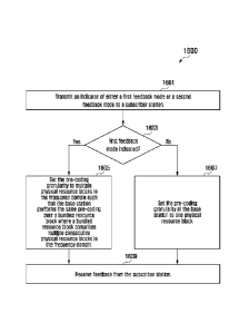
and a controller
configured to: receive from a base station an indicator of whether the
subscriber station is
configured with precoding matrix indicator / rank indicator (PMI/RI)
reporting, identify that
same precoding is applied to all physical resource blocks within a resource
block group, if the
subscriber station is configured with the precoding matrix indicator/rank
indicator (PMI/RI)
reporting based on the indicator and the subscriber station is configured for
a predetermined
transmission mode, and transmit feedback based on the indicator to the base
station.
[10d] According to another aspect of the invention, there is provided a
method of
operating a subscriber station, the method comprising: receiving from a base
station an
indicator of whether the subscriber station is configured with precoding
matrix indicator / rank
CA 2786034 2018-06-26
. 81705129
,
2b
indicator (PMI/RI) reporting; identifying that same precoding is applied to
all physical
resource blocks within a resource block group, if the subscriber station is
configured with the
precoding matrix indicator/rank indicator (PMI/RI) reporting based on the
indicator and the
subscriber station is configured for a predetermined transmission mode; and
transmitting
feedback based on the indicator to the base station.
[ 1 I ] Before undertaking the DETAILED DESCRIPTION OF THE INVENTION
below, it may be advantageous to set forth definitions of certain words and
phrases used
throughout this patent document: the terms "include" and "comprise," as well
as
CA 2786034 2018-06-26
CA 02786034 2012-06-28
WO 2011/083972 PCT/KR2011/000062
3
derivatives thereof, mean inclusion without limitation; the term "or," is
inclusive,
meaning and/or; the phrases "associated with" and "associated therewith," as
well as
derivatives thereof, may mean to include, be included within, interconnect
with,
contain, be contained within, connect to or with, couple to or with, be
communicable
with, cooperate with, interleave, juxtapose, be proximate to, be bound to or
with, have,
have a property of, or the like; and the term "controller" means any device,
system or
part thereof that controls at least one operation, such a device may be
implemented in
hardware, firmware or software, or some combination of at least two of the
same. It
should be noted that the functionality associated with any particular
controller may be
centralized or distributed, whether locally or remotely. Definitions for
certain words
and phrases are provided throughout this patent document, those of ordinary
skill in the
art should understand that in many, if not most instances, such definitions
apply to
prior, as well as future uses of such defined words and phrases.
Advantageous Effects of Invention
[12] According to the present invention, the OFDM is adopted as the DL
transmission
scheme in 3GPP LTE.
Brief Description of Drawings
[13] For a more complete understanding of the present disclosure and its
advantages,
reference is now made to the following description taken in conjunction with
the ac-
companying drawings, in which like reference numerals represent like parts:
[14] FIGURE 1 illustrates an exemplary wireless network that transmits
messages in the
uplink according to the principles of this disclosure;
[15] FIGURE 2 is a high-level diagram of an orthogonal frequency division
multiple
access (OFDMA) transmitter according to one embodiment of this disclosure;
[16] FIGURE 3 is a high-level diagram of an OFDMA receiver according to one
em-
bodiment of this disclosure;
[17] FIGURE 4 illustrates a diagram of a base station in communication with
a plurality
of mobile stations according to an embodiment of this disclosure;
[18] FIGURE 5 illustrates a spatial division multiple access (SDMA) scheme
according to
an embodiment of this disclosure;
[19] FIGURE 6 illustrates dedicated reference signal (DRS) patterns that
support two and
four layer transmissions according to an embodiment of this disclosure;
[20] FIGURE 7 illustrates DRS patterns that support eight layer
transmissions according
to an embodiment of this disclosure;
[21] FIGURE 8 illustrates a table depicting the use of a one bit signaling
to turn on or turn
off resource block (RB) bundling according to an embodiment of this
disclosure;
11221 FIGURE 9 illustrates a table depicting the use of available downlink
control in-
CA 02786034 2012-06-28
WO 2011/083972 PCT/KR2011/000062
4
formation (DCI) code-points to turn on or turn off resource block RB bundling
according to an embodiment of this disclosure;
[23] FIGURE 10 illustrates subbands bundled together according to an
embodiment of
this disclosure;
[24] FIGURE 11 illustrates a DCI format 2C according to an embodiment of
this
disclosure;
[25] FIGURE 12 illustrates a table depicting restricted subsets according
to an em-
bodiment of this disclosure;
[26] FIGURE 13 illustrates a table depicting a mapping of states in a
restricted subset to
codepoints in DCI format 2C according to an embodiment of this disclosure;
[27] FIGURE 14 illustrates a table depicting restricted subsets according
to another em-
bodiment of this disclosure;
[28] FIGURE 15 illustrates a table depicting a mapping of states in a
restricted subset to
codepoints in DCI format 2C according to another embodiment of this
disclosure;
[29] FIGURE 16 illustrates a method of operating a base station according
to an em-
bodiment of this disclosure;
[30] FIGURE 17 illustrates a method of operating a subscriber station
according to an em-
bodiment of this disclosure;
[31] FIGURE 18 illustrates a method of operating a base station according
to another em-
bodiment of this disclosure; and
[32] FIGURE 19 illustrates a method of operating a subscriber station
according to
another embodiment of this disclosure.
Mode for the Invention
[33] FIGURES 1 through 19, discussed below, and the various embodiments
used to
describe the principles of the present disclosure in this patent document are
by way of
illustration only and should not be construed in any way to limit the scope of
the
disclosure. Those skilled in the art will understand that the principles of
the present
disclosure may be implemented in any suitably arranged wireless communication
system.
[34] With regard to the following description, it is noted that the Long
Term Evolution
(LTE) term "node B" is another term for "base station" used below. Also, the
LTE
term "user equipment" or "UE" is another term for "subscriber station" used
below.
[35] FIGURE 1 illustrates exemplary wireless network 100, which transmits
messages
according to the principles of the present disclosure. In the illustrated
embodiment,
wireless network 100 includes base station (BS) 101, base station (BS) 102,
base
station (BS) 103, and other similar base stations (not shown).
[36] Base station 101 is in communication with Internet 130 or a similar IP-
based network
CA 02786034 2012-06-28
WO 2011/083972 PCT/KR2011/000062
(not shown).
[37] Base station 102 provides wireless broadband access to Internet 130 to
a first
plurality of subscriber stations within coverage area 120 of base station 102.
The first
plurality of subscriber stations includes subscriber station 111, which may be
located
in a small business (SB), subscriber station 112, which may be located in an
enterprise
(E), subscriber station 113, which may be located in a WiFi hotspot (HS),
subscriber
station 114, which may be located in a first residence (R), subscriber station
115,
which may be located in a second residence (R), and subscriber station 116,
which may
be a mobile device (M), such as a cell phone, a wireless laptop, a wireless
PDA, or the
like.
[38] Base station 103 provides wireless broadband access to Internet 130 to
a second
plurality of subscriber stations within coverage area 125 of base station 103.
The
second plurality of subscriber stations includes subscriber station 115 and
subscriber
station 116. In an exemplary embodiment, base stations 101-103 may communicate
with each other and with subscriber stations 111-116 using OFDM or OFDMA
techniques.
[39] While only six subscriber stations are depicted in FIGURE 1, it is
understood that
wireless network 100 may provide wireless broadband access to additional
subscriber
stations. It is noted that subscriber station 115 and subscriber station 116
are located on
the edges of both coverage area 120 and coverage area 125. Subscriber station
115 and
subscriber station 116 each communicate with both base station 102 and base
station
103 and may be said to be operating in handoff mode, as known to those of
skill in the
art.
[40] Subscriber stations 111-116 may access voice, data, video, video
conferencing, and/
or other broadband services via Internet 130. In an exemplary embodiment, one
or
more of subscriber stations 111-116 may be associated with an access point
(AP) of a
WiFi WLAN. Subscriber station 116 may be any of a number of mobile devices,
including a wireless-enabled laptop computer, personal data assistant,
notebook,
handheld device, or other wireless-enabled device. Subscriber stations 114 and
115
may be, for example, a wireless-enabled personal computer (PC), a laptop
computer, a
gateway, or another device.
[41] FIGURE 2 is a high-level diagram of an orthogonal frequency division
multiple
access (OFDMA) transmit path 200. FIGURE 3 is a high-level diagram of an or-
thogonal frequency division multiple access (OFDMA) receive path 300. In
FIGURES
2 and 3, the OFDMA transmit path 200 is implemented in base station (BS) 102
and
the OFDMA receive path 300 is implemented in subscriber station (SS) 116 for
the
purposes of illustration and explanation only. However, it will be understood
by those
skilled in the art that the OFDMA receive path 300 may also be implemented in
BS
CA 02786034 2012-06-28
WO 2011/083972 PCT/KR2011/000062
6
102 and the OFDMA transmit path 200 may be implemented in SS 116.
[42] The transmit path 200 in BS 102 comprises a channel coding and
modulation block
205, a serial-to-parallel (S-to-P) block 210, a Size N Inverse Fast Fourier
Transform
(IFFT) block 215, a parallel-to-serial (P-to-S) block 220, an add cyclic
prefix block
225, an up-converter (UC) 230, a reference signal multiplexer 290, and a
reference
signal allocator 295.
[43] The receive path 300 in SS 116 comprises a down-converter (DC) 255, a
remove
cyclic prefix block 260, a serial-to-parallel (S-to-P) block 265, a Size N
Fast Fourier
Transform (FFT) block 270, a parallel-to-serial (P-to-S) block 275, and a
channel
decoding and demodulation block 280.
[44] At least some of the components in FIGURES 2 and 3 may be implemented
in
software while other components may be implemented by configurable hardware or
a
mixture of software and configurable hardware. In particular, it is noted that
the FFT
blocks and the IFFT blocks described in the present disclosure document may be
im-
plemented as configurable software algorithms, where the value of Size N may
be
modified according to the implementation.
[45] Furthermore, although the present disclosure is directed to an
embodiment that im-
plements the Fast Fourier Transform and the Inverse Fast Fourier Transform,
this is by
way of illustration only and should not be construed to limit the scope of the
disclosure. It will be appreciated that in an alternate embodiment of the
disclosure, the
Fast Fourier Transform functions and the Inverse Fast Fourier Transform
functions
may easily be replaced by Discrete Fourier Transform (DFT) functions and
Inverse
Discrete Fourier Transform (IDFT) functions, respectively. It will be
appreciated that,
for DFT and IDFT functions, the value of the N variable may be any integer
number
(i.e., 1, 2, 3, 4, etc.), while for FFT and IFFT functions, the value of the N
variable may
be any integer number that is a power of two (i.e., 1, 2, 4, 8, 16, etc.).
[46] In BS 102, channel coding and modulation block 205 receives a set of
information
bits, applies coding (e.g., Turbo coding) and modulates (e.g., QPSK, QAM) the
input
bits to produce a sequence of frequency-domain modulation symbols. Serial-to-
parallel
block 210 converts (i.e., de-multiplexes) the serial modulated symbols to
parallel data
to produce N parallel symbol streams where N is the IFFT/FFT size used in BS
102
and SS 116. Size N IFFT block 215 then performs an IFFT operation on the N
parallel
symbol streams to produce time-domain output signals. Parallel-to-serial block
220
converts (i.e., multiplexes) the parallel time-domain output symbols from Size
N IFFT
block 215 to produce a serial time-domain signal. Add cyclic prefix block 225
then
inserts a cyclic prefix to the time-domain signal. Finally, up-converter 230
modulates
(i.e., up-converts) the output of add cyclic prefix block 225 to RF frequency
for
transmission via a wireless channel. The signal may also be filtered at
baseband before
CA 02786034 2012-06-28
WO 2011/083972
PCT/KR2011/000062
7
conversion to RF frequency. In some embodiments, reference signal multiplexer
290 is
operable to multiplex the reference signals using code division multiplexing
(CDM) or
time/frequency division multiplexing (TFDM). Reference signal allocator 295 is
operable to dynamically allocate reference signals in an OFDM signal in
accordance
with the methods and system disclosed in the present disclosure.
11471 The transmitted RF signal arrives at SS 116 after passing through the
wireless
channel and reverse operations performed at BS 102. Down-converter 255 down-
converts the received signal to baseband frequency and remove cyclic prefix
block 260
removes the cyclic prefix to produce the serial time-domain baseband signal.
Serial-
to-parallel block 265 converts the time-domain baseband signal to parallel
time domain
signals. Size N FFT block 270 then performs an FFT algorithm to produce N
parallel
frequency-domain signals. Parallel-to-serial block 275 converts the parallel
frequency-
domain signals to a sequence of modulated data symbols. Channel decoding and
de-
modulation block 280 demodulates and then decodes the modulated symbols to
recover the original input data stream.
[48] Each of base stations 101-103 may implement a transmit path that is
analogous to
transmitting in the downlink to subscriber stations 111-116 and may implement
a
receive path that is analogous to receiving in the uplink from subscriber
stations
111-116. Similarly, each one of subscriber stations 111-116 may implement a
transmit
path corresponding to the architecture for transmitting in the uplink to base
stations
101-103 and may implement a receive path corresponding to the architecture for
receiving in the downlink from base stations 101-103.
[49] The total bandwidth in an OFDM system is divided into narrowband
frequency units
called subcarriers. The number of subcarriers is equal to the FFT/IFFT size N
used in
the system. In general, the number of subcarriers used for data is less than N
because
some subcarriers at the edge of the frequency spectrum are reserved as guard
sub-
carriers. In general, no information is transmitted on guard subcarriers.
[50] The transmitted signal in each downlink (DL) slot of a resource block
is described by
a resource grid of DL _RB subcarriers and DL OFDM
symbols. The
N N
12B sc N syrnb
quantity 1. TAW. depends on the downlink transmission bandwidth configured in
the
v RB
cell and fulfills
min DL < Armax
DL , where it T min, D
RB
1 v RE
RB RE
and max,D I are the smallest and largest downlink bandwidth,
respectively,
N RB
supported. In some embodiments, subcarriers are considered the smallest
elements that
CA 02786034 2012-06-28
WO 2011/083972
PCT/KR2011/000062
8
are capable of being modulated.
[51] In case of multi-antenna transmission, there is one resource grid
defined per antenna
port.
[52] Each element in the resource grid for antenna port is called a
resource element
(RE) and is uniquely identified by the index pair it- 1) r in a slot where
DL RB and ________________________________ are the
indices in the
k-0,...,N RBN õ -1 /-0,"=, ,symb
frequency and time domains, respectively. Resource element 7-,) on
antenna
port corresponds to the complex value (p).
If there is no risk for confusion or
a ic
no particular antenna port is specified, the index may be dropped.
[53] In LTE, DL reference signals (RSs) are used for two purposes. First,
UEs measure
channel quality information (CQI), rank information (RI) and precoder matrix
in-
formation (PMI) using DL RSs. Second, each UE demodulates the DL transmission
signal intended for itself using the DL RSs. In addition, DL RSs are divided
into three
categories: cell-specific RSs, multi-media broadcast over a single frequency
network
(MBSFN) RSs, and UE-specific RSs or dedicated RSs (DRSs).
11541 Cell-specific reference signals (or common reference signals: CRSs)
are transmitted
in all downlink subframes in a cell supporting non-MBSFN transmission. If a
subframe
is used for transmission with MBSFN, only the first a few (0, 1 or 2) OFDM
symbols
in a subframe can be used for transmission of cell-specific reference symbols.
The
notation is used to denote a resource element used for reference
signal
transmission on antenna port .
11551 UE-
specific reference signals (or dedicated RSs: DRSs) are supported for single-
antenna-port transmission on the Physical Downlink Shared Channel (PDSCH) and
are
transmitted on antenna port 5. The UE is informed by higher layers whether the
UE-
specific reference signal is present and is a valid phase reference for PDSCH
de-
modulation or not. UE-specific reference signals are transmitted only on the
resource
blocks upon which the corresponding PDSCH is mapped.
[56] The time resources of an LTE system are partitioned into 10 msec
frames, and each
frame is further partitioned into 10 subframes of one msec duration each. A
subframe
is divided into two time slots, each of which spans 0.5 msec. A subframe is
partitioned
in the frequency domain into multiple resource blocks (RBs), where an RB is
composed of 12 subcarriers.
CA 02786034 2012-06-28
WO 2011/083972 PCT/KR2011/000062
9
[571 FIGURE 4 illustrates a diagram 400 of a base station 420 in
communication with a
plurality of mobile stations 402, 404, 406, and 408 according to an embodiment
of this
disclosure.
[58] As shown in FIGURE 4, base station 420 simultaneously communicates
with
multiple of mobile stations through the use of multiple antenna beams, each
antenna
beam is formed toward its intended mobile station at the same time and same
frequency. Base station 420 and mobile stations 402, 404, 406, and 408 are
employing
multiple antennas for transmission and reception of radio wave signals. The
radio wave
signals can be Orthogonal Frequency Division Multiplexing (OFDM) signals.
[59] In this embodiment, base station 420 performs simultaneous beamforming
through a
plurality of transmitters to each mobile station. For instance, base station
420 transmits
data to mobile station 402 through a beamformed signal 410, data to mobile
station
404 through a beamformed signal 412, data to mobile station 406 through a
beamformed signal 414, and data to mobile station 408 through a beamformed
signal
416. In some embodiments of this disclosure, base station 420 is capable of
simul-
taneously beamforming to the mobile stations 402, 404, 406, and 408. In some
em-
bodiments, each beamformed signal is formed toward its intended mobile station
at the
same time and the same frequency. For the purpose of clarity, the
communication from
a base station to a mobile station may also be referred to as downlink
communication,
and the communication from a mobile station to a base station may be referred
to as
uplink communication.
[60] Base station 420 and mobile stations 402, 404, 406, and 408 employ
multiple
antennas for transmitting and receiving wireless signals. It is understood
that the
wireless signals may be radio wave signals, and the wireless signals may use
any
transmission scheme known to one skilled in the art, including an Orthogonal
Frequency Division Multiplexing (OFDM) transmission scheme.
[61] Mobile stations 402, 404, 406, and 408 may be any device that is
capable receiving
wireless signals. Examples of mobile stations 402, 404, 406, and 408 include,
but are
not limited to, a personal data assistant (PDA), laptop, mobile telephone,
handheld
device, or any other device that is capable of receiving the beamformed
transmissions.
[62] The use of multiple transmit antennas and multiple receive antennas at
both a base
station and a single mobile station to improve the capacity and reliability of
a wireless
communication channel is known as a Single User Multiple Input Multiple Output
(SU-MIMO) system. A MIMO system promises linear increase in capacity with K
where K is the minimum of number of transmit (M) and receive antennas (N)
(i.e.,
K=min(M,N)). A MIMO system can be implemented with the schemes of spatial mul-
tiplexing, a transmit/receive beamforming, or transmit/receive diversity.
[63] As an extension of SU-MIMO, multi-user MIMO (MU-MIMO) is a
communication
CA 02786034 2012-06-28
WO 2011/083972 PCT/KR2011/000062
scenario where a base station with multiple transmit antennas can
simultaneously com-
municate with multiple mobile stations through the use of multi-user
beamforming
schemes such as Spatial Division Multiple Access (SDMA) to improve the
capacity
and reliability of a wireless communication channel.
[64] FIGURE 5 illustrates an SDMA scheme according to an embodiment of this
disclosure.
[65] As shown in FIGURE 5, base station 420 is equipped with 8 transmit
antennas while
mobile stations 402, 404, 406, and 408 are each equipped two antennas. In this
example, base station 420 has eight transmit antennas. Each of the transmit
antennas
transmits one of beamformed signals 410, 502, 504, 412, 414, 506, 416, and
508. In
this example, mobile station 402 receives beamformed transmissions 410 and
502,
mobile station 404 receives beamformed transmissions 504 and 412, mobile
station
406 receives beamformed transmissions 506 and 414, and mobile station 408
receives
beamformed transmissions 508 and 416.
[66] Since base station 420 has eight transmit antenna beams (each antenna
beams one
stream of data streams), eight streams of beamformed data can be formed at
base
station 420. Each mobile station can potentially receive up to 2 streams
(beams) of data
in this example. If each of the mobile stations 402, 404, 406, and 408 was
limited to
receive only a single stream (beam) of data, instead of multiple streams simul-
taneously, this would be multi-user beamforming (i.e., MU-BF).
[67] In Release 8 LTE systems, a UE is required to perform channel
estimation based on
common reference signals (CRSs) over the entire bandwidth. Once channel
estimation
is performed, the UE performs demodulation based on different transmission
modes
indicated by the different formats of the downlink control information. For
example,
when downlink spatial multiplexing is performed, downlink control information
(DCI)
format 2 is used, and the UE performs demodulation based on the resource
assignment
and TPMI (transmission PMI) contained in the DCI format. For example, in 3GPP
TS
36.212 v 8.8.0, "E-UTRA, Multiplexing and Channel Coding", December 2009, the
definition of TPMI is defined in Table 5.3.3.1.5 - 4 (2 antenna ports) and in
Table
5.3.3.1.5 -5 (4 antenna ports) of Section 5.3.3.1.5, which is hereby
incorporated by
reference into the present application as if fully set forth herein.
[68] The eNodeB indicates whether it is wideband precoding or subband
precoding to UE
based on the UE's feedback, and the UE performs downlink demodulation ac-
cordingly.
[69] In LTE-Advanced (LTE-A) systems, the downlink demodulation is based on
dedicated reference signals (DRS), a.k.a. UE-specific reference signals (UE-
RS).
[70] In LTE-Advanced systems, demodulation of the data channel is based
precoded UE-
specific reference signal, that is, the reference signals are precoded using
the same
CA 02786034 2012-06-28
WO 2011/083972 PCT/KR2011/000062
11
precoder as the data channel as described in R1-090529 -Way forward on CoMP
and
MIMO DL RS", Outcome of ad hoc discussions, January 2009, and R1-091066 "Way
forward on downlink reference signals for LTE-A", CATT, CMCC, Ericsson,
Huawei,
LGE, Motorola. Nokia, Nokia Siemens Networks, Nortel, Panasonic, Philips,
Qualcomm Europe, Samsung, Texas Instruments, March 2009, both of which are
hereby incorporated by reference into the present application as if fully set
forth herein.
[71] RSs targeting PDSCH demodulation (for LTE-A operation) are UE specific
and are
transmitted only in scheduled RBs and the corresponding layers. Different
layers can
target the same or different UEs. The design principle is an extension of the
concept of
Re1-8 UE-specific RS (used for beamforming) to multiple layers. RSs on
different
layers are mutually orthogonal. RSs and data are subject to the same precoding
operation, and complementary use of Re1-8 CRS by the UE is not precluded.
[72] In R1-094413, "Way forward on the details of DCI format 2B for
enhanced DL
transmission," 3GPP RAN1#58bis, Miyazaki, October 2009, which is hereby in-
corporated by reference into the present application as if fully set forth
herein, an
agreement has been made for DCI format 2B as follows:
[73] - The DCI Format 2B is based on DCI Format 2A;
[74] - 1 bit is added for the source channel identifier (SC-1D);
[75] - The Swap Flag is removed;
[76] - For rank 1 transmission, the new data indicator (NDI) bit of the
disabled transport
block is re-used to indicate port information. A value of 0 is used to
indicate an
enabled transport block (TB) associated with port 7. A value of 1 is used to
indicate an
enabled transport block associated with port 8; and
[77] - For rank 2 transmission, TB1 is associated with port 7, and TB2
associated with
port 8.
[78] DCI format 2C can be constructed based on DCI format 2B for Rel. 10
transmission
modes for facilitating dynamic SU- and MU-MIMO switching.
[79] Since an eNodeB could potentially perform resource block (RB)-based
precoding,
the baseline granularity for channel estimation and demodulation is one RB.
However,
as disclosed in R1-093105, "UE-RS Patterns for LTE-A", Qualcomm Europe, August
2009, which is hereby incorporated by reference into the present application
as if fully
set forth herein, "RB-bundling" (bundle contiguous RBs together to perform
channel
estimation and demodulation) will help higher rank (i.e., rank 5 to 8)
transmissions
achieve adequate channel estimation accuracy along with a low overhead. It is
also
disclosed in R1-094575, "Discussion on DM-RS for LTE-Advanced", Samsung,
November 2009; R1-094438, "On Rel-10 DM RS design for rank 5-8", Ericsson, ST-
Ericsson, November 2009; and R1-094548, "Further investigation on DMRS design
for LTE-A", CATT, November 2009, which are hereby incorporated by reference
into
CA 02786034 2012-06-28
WO 2011/083972 PCT/KR2011/000062
12
the present application as if fully set forth herein, that "RB bundling" could
be used to
balance the transmission power imbalance across OFDM symbols for some high
rank
DM-RS patterns.
[80] FIGURE 6 illustrates dedicated reference signal (DRS) patterns that
support two and
four layer transmissions according to an embodiment of this disclosure.
11811 DRS patterns 601 and 603 illustrate pilot patterns that can support
up to 2 layer trans-
missions. DRS REs labeled with 0,1 in DRS pattern 601 carry DRS for layer 0
and 1
with the RSs of the two layers code-division multiplexed (CDMed). Similarly,
for DRS
REs labeled with 2,3 in DRS pattern 603 carry DRS for layer 2 and 3 with the
RSs of
the two layers code-division multiplexed (CDMed).
[82] In the two adjacent DRS REs tabled with 0,1, DRS symbols [r0 rl] for
layer 0 are
mapped to the two REs spread by a Walsh code [1 11, which results in [1-0 rl],
while
DRS symbols r2 and r3 for layer 1 are mapped to the two REs spread by a Walsh
code
[1 -11, which results in [r2 -r3[.
[83] DRS pattern 605 illustrates a pilot pattern that can support up to
four layer trans-
missions, where the DRS REs are again partitioned into two, those labeled with
0,1
and those with 2,3. In this pattern, the DRS REs labeled with 0,1 carry DRSs
for layer
0 and 1 with the RSs of the two layers code-division multiplexed (CDMed), and
the
DRS REs labeled with 2,3 carry DRSs for layer 2 and 3 with the RSs of the two
layers
code-division multiplexed(CDMed).
[84] FIGURE 7 illustrates DRS patterns that support eight layer
transmissions according
to an embodiment of this disclosure.
[851 With regard to FIGURE 7, REs labeled with alphabet X, where X is one
of G, H, I, J,
L, K, are used for carrying a number of DRS among the 8 DRS, where the number
of
DRS are CDM'ed. DRS pattern 701 is based on spreading factor 2 CDM across two
time-adjacent REs with the same alphabet label. DRS pattern 703 is based on
spreading factor 4 CDM across two groups of two time-adjacent REs with the
same
alphabet label. In this embodiment, the 8 antenna ports in a Rank-8 pattern
are referred
to as antenna ports 4.5,6,7,8,9.10,11 in the sequel to distinguish them from
the antenna
ports in Rank-2 and Rank-4 patterns.
[86] It is noted that in Re1-8 LTE, antenna ports 0, 1, 2, 3, 4, 5 are used
for CRS, MBSFN
RS and Re1-8 DRS. Hence, if the numbering convention extending Re1-8 LTE is
followed, the new antenna port numbers will start from 6. Rank-2 pattern will
have
antenna ports 6,7. Rank-4 pattern will have antenna ports 7,8,9,10. Rank-8
pattern will
have antenna ports 11, 12, 13, 14, 15, 16, 17, 18.
[87] In one embodiment of DRS pattern 701, G carries DRS 4, 5. H carries
DRS 6,7. I
carries DRS 8,9. J carries DRS 10,11. In one embodiment of DRS pattern 703, K
carries DRS 4,5,6,7; and L carries DRS 8,9,10,11.
CA 02786034 2012-06-28
WO 2011/083972 PCT/KR2011/000062
13
[881 Each of the DM-RS patterns in FIGURES 6 and 7 is RB based.
Accordingly, a UE
could perform channel estimation and demodulation per RB. Alternatively, if RB
bundling is supported, the UE could perform channel estimation and
demodulation
jointly across bundled RBs. In this way, the performance of channel estimation
and de-
modulation can be improved.
[891 RB-bundling gain is achieved only when an eNodeB performs the same
downlink
precoding vectors across the bundled RBs. Accordingly, a UE will have to
perform
channel estimation and demodulation over the bundled RBs jointly.
[90] In other words, RB bundling will reduce the precoding flexibility
since the precoding
vectors within the bundled RBs have to be the same. This clearly suggests a
trade-off
between gains from increasing channel interpolation span in frequency versus
losses
from increasing frequency selective precoding granularity.
[91] The advantage of RB bundling is that channel estimation performance is
improved.
However, the eNodeB cannot perform per RB encoding if the eNode B does not
receive per RB feedback from the UE due to large overhead.
[92] The advantage of not enabling RB bundling is that the eNodeB does not
need the UE
to feedback the PMI in order to perform channel estimation and demodulation.
Instead,
the eNodeB could rely upon uplink channel sounding in TDD systems.
Furthermore,
the eNodeB would have the flexibility to petform per RB pre-coding, which
results in
a higher pre-coding gain. However, the UE would then have to perform per RB
channel estimation if the channel is very selective.
[93] Therefore, it would be advantageous to be able to turn on or off the
feature of RB-
bundling depending on the channel conditions.
[94] This disclosure provides systems and methods for enabling RB-bundling.
[95] In some embodiments of this disclosure, an eNodeB transmits an
indication to turn
on or off the feature of RB-bundling to a UE.
[96] When RB-bundling is turned on or enabled, the eNodeB performs the same
downlink
precoding vectors across a number of continuous RBs (the RB-bundling size),
and the
UE petforms channel estimation and demodulation jointly on the bundled RBs.
When
RB-bundling is turning off or not enabled, the eNodeB performs downlink
precoding
on a per-RB basis, and the UE performs channel estimation and demodulation on
a per
RB basis as well.
[97] The indication from the eNodeB to the UE to indicate whether RB
bundling is
enabled can be achieved several ways.
[98] In some embodiments of this disclosure, a signaling from the eNodeB to
UE in-
dicating whether RB-bundling is enabled can be either semi-statically signaled
through
higher-layer signaling or dynamically signaled utilizing the available code-
points in a
DCI format. Furthermore, this signaling can be either explicit or implicit.
CA 02786034 2012-06-28
WO 2011/083972 PCT/KR2011/000062
14
[991 FIGURE 8 illustrates a table 800 depicting the use of a one bit
signaling to turn on or
turn off resource block (RB) bundling according to an embodiment of this
disclosure.
[100] In some embodiments of this disclosure, explicit signaling is used to
turn on or off
RB-bundling. For example, higher layer signaling is used to semi-statistically
turn on
or off RB bundling. For example, as shown in table 800, a one bit signaling
can be
used to semi-statistically turn on or turn off RB bundling. In this particular
example, a
first value of "0" indicates a first state in which RB bundling is turned off
or disabled.
A second value of "1" indicates a second state in which RB bundling is turned
on or
enabled. In another example, a sequence of bits is used to indicate states
related to RB-
bundling. One particular state indicated by this sequence of bits could be
interpreted at
the UE as turning off RB-bundling.
[101] FIGURE 9 illustrates a table 900 depicting the use of available
downlink control in-
formation (DCI) code-points to turn on or turn off resource block RB bundling
according to an embodiment of this disclosure.
[102] As shown in FIGURE 9, available DCI code-points are also used to
dynamically turn
on or off RB bundling. For example, in DCI format 2X, a state is defined to
turn on RB
bundling by adding an additional field to DCI format 2C. In this particular
example, a
first state indicated by the additional field is a state in which RB bundling
is turned on
or enabled. A second state indicated by the additional field is a state in
which RB
bundling is turned off or disabled.
[103] In some embodiments of this disclosure, implicit signaling is used to
turn on or off
RB-bundling. For example, whether RB bundling is enabled is based on a
specific
transmission mode, the DCI format used for a DL grant, the transmission
scheme, and
the radio network temporary identifier (RNTI) configuration.
[104] For example, RB bundling is turned on or enabled if a UE is
configured in Rel. 9
transmission mode (mode 8 in 3GPP 36.213), and if the UE received a physical
downlink shared channel (PDSCH) packet scheduled with DCI format 2B.
[105] In addition, if the UE receives a PDSCH packet scheduled with DCI
format 1A and
the associated transmission scheme is TxD (scheduled by semi-persistent
scheduling
(SPS) RNTI, and for the case when the physical broadcast channel (PBCH)
signals
multiple antenna ports), then RB bundling is turned off or disabled. If the UE
receives
a PDSCH packet scheduled with DCI format 1A, and the associated transmission
scheme is single antenna port transmission (1. scheduled by SPS-RNTI, and for
the
case when the PBCH signals one antenna port: or 2. scheduled by cell radio
network
temporary identifier (C-RNTI)), then RB bundling is turned on or enabled.
[106] For example, RB bundling is turned on or enabled if a UE is
configured in Rel. 10
transmission mode for both SU and MU MIMO transmission, and if the UE received
a
PDSCH packet scheduled with DCI format 2C (DCI format in Rel-10 used to
support 2
CA 02786034 2012-06-28
WO 2011/083972 PCT/KR2011/000062
codeword MIMO transmission).
[107] In addition, if the UE receives a PDSCH packet scheduled with DCI
format 1A, and
the associated transmission scheme is TxD (scheduled by SPS RNTI, and for the
case
when the PBCH signals multiple antenna ports), then RB bundling is turned off
or
disabled. If the UE receives a PDSCH packet scheduled with DCI format 1A, and
the
associated transmission scheme is single antenna port transmission (1.
scheduled by
SPS-RNTI, and for the case when the PBCH signals one antenna port; or 2.
scheduled
by C-RNTI), then RB bundling is turned on or enabled.
[108] In other embodiments of this disclosure, RB bundling is turned on or
off based on a
specific feedback mode.
[109] For example, if a UE is configured in Re1-9 and Rel-10 transmission
modes and
precoding matrix indicator/rank indicator (PMI/RI) feedback is configured, RB
bundling is turned on or enabled. Otherwise, if the UE is configured in Rel-10
and
beyond Rel-10 transmission modes and PMI/RI feedback is not configured, RB
bundling is turned off or disabled. This is because the application scenario
for con-
figuring PMI/RI feedback is for frequency-division duplexing (FDD) systems
while
the application scenario for configuring PMI/RI feedback is not for time-
division
duplexing TDD systems. As discussed early in TDD systems, an eNodeB may obtain
the channel state information using uplink sounding to perform frequency
selective
precoding. In this case, PRB bundling should be turned off accordingly.
Furthermore,
even in FDD systems, when the eNodeB decides to perform open-loop operations,
the
eNodeB will not configure the UE to feedback PMI/RI. Therefore, PRB bundling
is
also turned off in this case to allow for flexible operation at the eNodeB.
[110] In another example, when wideband channel quality indicator
(CQI)/PMI/RI
(wideband CQI) feedback mode is configured, RB bundling is turned on or
enabled.
When subband CQI/PMI/RI (subband CQI) feedback mode is configured, RB bundling
is turned off or disabled.
[111] In other embodiments of this disclosure, an RB bundling on/off
indication can also
be realized through other system indications from the eNodeB to the UE. For
example,
RB bundling is enabled once the rank indicator (RI) is greater than a
predetermined
value.
[112] In yet other embodiments of this disclosure, RB bundling is always on
for de-
modulation using Rel. 9 or Rel. 10 UE-RS.
[113] In order to perform different types of feedback reports, the UE is
configured by the
eNodeB in different feedback modes.
[114] In some embodiments of this disclosure, RB-bundling is turned on or
off based on
the specific feedback mode configured by the eNodeB.
[115] In one embodiment, RB-bundling is turned on or off based on the
specific physical
CA 02786034 2012-06-28
WO 2011/083972 PCT/KR2011/000062
16
uplink control channel (PUCCH) feedback mode.
[116] For example, RB bundling is turned on or enabled when when the UE is
configured
with PMI/RI reporting, and RB bundling is turned off or disabled when the UE
is not
configured with PMI/RI reporting.
[117] Accordingly, when the UE is configured with PMI/RI reporting, the pre-
coding
granularity at the eNodeB is multiple physical resource blocks. That is the
eNodeB
performs the same pre-coding over a bundled resource block where a bundled
resource
block comprises multiple consecutive physical resource blocks.
[118] Accordingly, when the UE is configured with PMI/RI reporting, the
feedback
granularity at the UE is set to multiple physical resource blocks such that
the UE
performs a channel estimation over a bundled resource block where a bundled
resource
block comprises multiple consecutive physical resource blocks.
[119] Furthermore, when the UE is not configured with PMI/RI reporting, the
pre-coding
granularity at the eNodeB is a single physical resource block. That is the
eNodeB
performs pre-coding on a per physical resource block basis.
[120] Accordingly, when the UE is not configured with PMI/RI reporting, the
feedback
granularity at the UE is set to a single physical resource block such that the
UE
performs a channel estimation on a per physical resource block basis.
[121] In 3GPP TS 36.213 v 8.8.0, "E-UTRA, Physical Layer Procedures", Dec
2009,
which is hereby incorporated by reference into the present application as if
fully set
forth herein, depending on the mode of periodic PUCCH feedback, RB bundling is
turned on or enabled when the UE is configured in mode 1-1 and mode 2-1 of
Table
7.2.2-1, and RB bundling is turned off or disabled when the UE is configured
in mode
1-0 and mode 2-0.
[122] In other embodiments of this disclosure, RB-bundling is turned on or
off based on
the based on the specific physical uplink shared channel (PUSCH) feedback
mode.
[123] In some embodiments of this disclosure, RB bundling is turned on or
enabled when
the UE is configured for "single PMI" and/or "multiple PMI" feedback, and RB
bundling is turned off or disabled otherwise.
[124] For example, RB bundling is turned on or enabled when the UE is
configured for
"single PMI" feedback, and RB bundling is turned off or disabled when the UE
is
configured for "No PMI" or "Multiple PMI" feedback.
[125] In another example, RB bundling is turned on or enabled when the UE
is configured
for "single PMI" and "Multiple PMI" feedback, and RB bundling is turned off or
disabled when the UE is configured for "No PMI" feedback.
[126] In yet another example, RB bundling is turned on or enabled when the
UE is
configured for "Multiple PMI" feedback, and RB-bundling is turned off or
disabled
when the UE is configured for "No PMI" or "Single PMI" feedback.
CA 02786034 2012-06-28
WO 2011/083972 PCT/KR2011/000062
17
[127] For example, in 3GPP TS 36.213 v 8.8.0, "E-UTRA, Physical Layer
Procedures",
Dec 2009, depending on the mode of aperiodic PUSCH feedback, RB bundling is
turned on or enabled when the UE is configured in mode 3-1, and RB bundling is
turned off or disabled in other feedback modes.
[128] Once RB bundling is on or enabled, the granularity of the RB bundling
has to be
decided. As described earlier, the granularity of the RB bundling refers to
the number
of continuous PRBs used for channel estimation and demodulation.
[129] In some embodiments of this disclosure, the RB-bundling granularity
is set to be the
unit of downlink resource allocation.
[130] For example, in 3GPP TS 36.211 v 8.8.0, "E-UTRA, Physical channels
and
modulation", Dec 2009, which is hereby incorporated by reference into the
present ap-
plication as if fully set forth herein, the unit of downlink resource
allocation is a
resource block group (RBG), the size of RBG is dependent on the total system
bandwidth. Therefore, the granularity of RB bundling can be the RBG size.
[131] In other embodiments of this disclosure, the RB-bundling granularity
is set to be the
feedback granularity. The feedback granularity refers to the number of
continuous RBs
used by the UE to perform PMI/CQI/RI feedback.
[132] For example, in 3GPP TS 36.211 v 8.8.0, "E-UTRA, Physical channels
and
modulation", Dec 2009, feedback granularity for PUSCH feedback is the subband
size
defined in Section 7.2.1 for higher layer-configured subband feedback or UE-
selected
subband feedback. The feedback granularity for PUCCH feedback is defined in
Section 7.2.2.
[133] Therefore, in some embodiments, the RB-bundling granularity is set to
be the
subband size of the PUCCH feedback as a function of the total system
bandwidth.
[134] Alternatively, the RB-bundling granularity is related to the subband
size of the
PUSCH feedback.
[135] For example, if RB bundling is turned on or enabled by the eNodeB
configuring
specific feedback mode, then the granularity of RB is the subband size of the
corre-
sponding feedback mode.
[136] FIGURE 10 illustrates subbands bundled together according to an
embodiment of
this disclosure.
[137] In yet other embodiments of this disclosure, the RB-bundling
granularity is set to be
jointly decided by the feedback granularity as well as the downlink resource
allocation
unit. Feedback granularity refers to the number of continuous RBs used by the
UE to
perform PMI/CQI/RI feedback.
[138] For example when a UE is configured to have PUSCH "Multiple PMI"
feedback, the
eNodeB would perform downlink precoding based on the UE feedback subband size,
and the UE would assume the RBs in the downlink resource allocation from the
same
CA 02786034 2012-06-28
WO 2011/083972 PCT/KR2011/000062
18
subband bundled together as shown in FIGURE 10.
[139] In FIGURE 10, a first subband 1010 includes a first RB bundle 1001,
and a second
subband 1020 includes a second RB bundle 1011. The first RB bundle 1001 and
the
second RB bundle 1011 are bundled together to form an RBG 1030.
[140] In further embodiments of this disclosure, the RB-bundling
granularity is set
according to the subband size associated with the configured feedback modes.
[141] In one such embodiment, the RB-bundling granularity depends on the
configured
PUSCH feedback modes.
[142] For example, when wideband feedback is configured (mode 3-1), all the
allocated
RBs are bundled to perform channel estimation and demodulation.
[143] In another example, when subband feedback is configured (mode 1-2,
mode 2-2), RB
bundling follows the subband size from the UE PUSCH feedback and/or the
resource
block group (RBG) size.
[144] In a further example, when no PMI feedback is configured (mode 2-0,
mode 3-0),
RB bundling is turned off or disabled.
[145] In some embodiments of this disclosure, the RB-bundling granularity
depends on the
configured PUCCH feedback modes.
[146] For example, when wideband feedback is configured (mode 1-1, mode 2-
1), RB
bundling follows the subband size from the PUCCH feedback (higher layer
configured
feedback subband size) and/or the RBG size.
[147] For example, when no PMI feedback is configured (mode 1-0, mode 2-0),
RB
bundling is turned off or disabled.
[148] In some embodiments of this disclosure, the size of RB bundling is
fixed.
[149] For example, the size of RB bundling can be an even number to
facilitate pattern
rotation of UE-RS patterns for higher ranks as suggested in R1-094575,
"Discussion
on DM-RS for LTE-Advanced", Samsung, November 2009, which is hereby in-
corporated by reference into the present application as if fully set forth
herein.
[150] FIGURE 11 illustrates a DCI format 2C 1100 according to an embodiment
of this
disclosure.
[151] As shown in FIGURE 11, in some embodiments of this disclosure, DCI
format 2C
1100 is constructed by adding a new N3-bit for the indication of a combination
of a
selected DM RS pattern and a DM RS index set to DCI format 2B to support
dynamic
switching of SU- and MU-MIMO. A new data indicator (NDI) bit of a disabled
transport block (TB) in DCI format 2B is used for indicating a DM RS index in
the
case of rank-1 indication in Re1-9 LTE. Hence, this embodiment uses codepoints
con-
structed by a combination of an NDI bit of a disabled TB, such as the NDI bit
in NDI
field 1101 or NDI field 1103, and the new N3-bit in the N3-bit field 1105 for
in-
dicating rank-1 states in the restricted subset.
CA 02786034 2012-06-28
WO 2011/083972 PCT/KR2011/000062
19
[152] FIGURE 12 illustrates a table 1200 depicting restricted subsets
according to an em-
bodiment of this disclosure.
[153] In some embodiments, a state in a restricted subset A is signalled by
DCI format 2C,
where the restricted subset A is shown in table 1200 as an example. In
particular em-
bodiments, the restricted subset A is constructed such that all possible
states from
Rank-2 patterns A and B are included, no Rank-2 states from Rank-4 are
included, and
only higher rank states are included from Rank-8.
[154] The motivations of this subset restriction are that:
[155] - rank 1 and rank 2 transmissions are supported with minimal UE-RS
overhead;
[156] - MU-MIMO is explicitly supported only for rank-1 with orthogonal UE-
RS in Rank-
2 and Rank-4 patterns; and
[157] - higher RS overhead is allowed only for ranks 3 or above.
[158] FIGURE 13 illustrates a table 1300 depicting a mapping of states in a
restricted
subset to codepoints in DCI format 2C according to an embodiment of this
disclosure.
[159] FIGURE 13 illustrates one example mapping of states in restricted
subset A to
codepoints in DCI format 2C.
[160] FIGURE 14 illustrates a table 1400 depicting restricted subsets
according to another
embodiment of this disclosure.
[161] In this embodiment, a state in restricted subset B is signalled by
DCI format 2C. In
this embodiment, the restricted subset B is constructed such that all possible
states
from Rank-2 patterns A and B are included, no Rank-2 states from Rank-4 are
included, and only higher rank states are included from Rank-8. The
motivations of
this subset restriction are that:
[162] - MU-MIMO is explicitly supported for rank-1 with orthogonal UE-RS in
Rank-2
and Rank-4 patterns;
[163] - MU-MIMO is explicitly supported for rank-2 with orthogonal UE-RS in
Rank-4
pattern; and
[164] - higher RS overhead is allowed for ranks 2 or above.
[165] FIGURE 15 illustrates a table 1500 depicting a mapping of states in a
restricted
subset to codepoints in DCI format 2C according to another embodiment of this
disclosure.
[166] FIGURE 15 illustrates one example mapping of states in restricted
subset B to
codepoints in DCI format 2C.
[167] FIGURE 16 illustrates a method 1600 of operating a base station
according to an em-
bodiment of this disclosure.
[168] The method 1600 includes transmitting an indication of either a first
feedback mode
or a second feedback mode to a subscriber station (block 1601) and determining
whether the first feedback mode is indicated by the indicator (block 1603).
The method
CA 02786034 2012-06-28
WO 2011/083972 PCT/KR2011/000062
1600 also includes setting the pre-coding granularity at the base station to
multiple
physical resource blocks in the frequency domain such that the base station
performs
the same pre-coding over a bundled resource block where a bundled resource
block
comprises multiple consecutive physical resource blocks in the frequency
domain if
the first feedback mode is indicated by the indicator (block 1605) and setting
the pre-
coding granularity at the base station to one physical resource block if the
second
feedback mode is indicated by the indicator (block 1607). The method 1600
further
includes receiving feedback from the subscriber station (block 1609).
[169] FIGURE 17 illustrates a method 1700 of operating a subscriber station
according to
an embodiment of this disclosure.
[170] The method 1700 includes receiving an indication of a first feedback
mode or a
second feedback mode from a base station (block 1701), and determining whether
the
first feedback mode is indicated by the indicator (block 1703). The method
1700 also
includes performing a channel estimation over a bundled resource block where a
bundled resource block comprises multiple consecutive physical resource blocks
in the
frequency domain if the first feedback mode is indicated by the indicator
(block 1705),
and performing channel estimation only on a per physical resource block basis
if the
second feedback mode is indicated by the indicator (block 1707). The method
1700
further includes transmitting the channel estimation as feedback to the base
station
(block 1709).
[171] FIGURE 18 illustrates a method 1800 of operating a base station
according to
another embodiment of this disclosure.
[172] The method 1800 includes transmitting an indication of whether a
subscriber station
is configured with precoding matrix indicator/rank indicator (PMURI) reporting
(block
1801), and determining whether the subscriber station is configured with
PMI/RI
reporting (block 1803). The method 1800 also includes setting the pre-coding
granularity at the base station to multiple physical resource blocks in the
frequency
domain such that the base station performs the same pre-coding over a bundled
resource block where a bundled resource block comprises multiple consecutive
physical resource blocks in the frequency domain if the subscriber station is
configured
with PMT/RT reporting (block 1805) and setting the pre-coding granularity at
the base
station to one physical resource block if the subscriber station is not
configured with
PMI/RI reporting (block 1807). The method 1800 further includes receiving
feedback
from the subscriber station (block 1809).
[173] FIGURE 19 illustrates a method 1900 of operating a subscriber station
according to
another embodiment of this disclosure.
[174] The method 1900 includes receiving from a base station an indication
of whether the
subscriber station is configured with precoding matrix indicator/rank
indicator
CA 02786034 2012-06-28
WO 2011/083972 PCT/KR2011/000062
21
(PMI/R1) reporting (block 1901), and determining whether the subscriber
station is
configured with PMI/RI reporting (block 1903). The method 1900 also includes
performing a channel estimation over a bundled resource block where a bundled
resource block comprises multiple consecutive physical resource blocks in the
frequency domain if the subscriber station is configured with PMI/RI reporting
(block
1905), and performing channel estimation only on a per physical resource block
basis
if the subscriber station is not configured with PMI/RI reporting (block
1907). The
method 1900 further includes transmitting the channel estimation as feedback
to the
base station (block 1909).
[175] Although the present disclosure has been described with an exemplary
embodiment,
various changes and modifications may be suggested to one skilled in the art.
It is
intended that the present disclosure encompass such changes and modifications
as fall
within the scope of the appended claims.