Note: Descriptions are shown in the official language in which they were submitted.
CA 02786045 2012-06-29
WO 2011/160725 PCT/EP2010/067047
1
INSTRUCTIONS FOR PERFORMING AN OPERATION ON A OPERAND IN MEMORY AND
SUBSEQUENTLY LOADING AN ORIGINAL VALUE OF SAID
OPERAND IN A REGISTER
FIELD ()Ii ' Ill, IN VEIN E1 ON
The present invention is related to con puter systems and more particularly to
computer
system processor instruction functionality.
BACKGROUND
Trademarks: IB MM(P) is a registered trademark of International Business
Machines
Corporation, Armonk, New York-, U.S.A. S/390, Z900, z990 and ziO and other
product
names may be registered trademarks or product names of International Business
Machines
Corporation or other companies.
IBM has created through the work of many highly talented engineers beginning
with
machines known as the IBM '; Sy>stein 360 in the 1960s to the present, a
special architecture
hich, because of its essential nature to a computing system, became known as
"the
mainframe" Whose principles of Opeiation_ state the areÃhiteà ture of th
machine by describing
the instructions which may be executed upon the ``mainf ame"' mp errr
ntatidyrr of the
instructions which had been invented by IB in entors and adopted, because of
their
significant contribution to improving the state of the computing machine
represented by `tithe
mainframe"', as significant contributions by inclusion in IBM's s Principles
of Op-craT1011 as
stated over the years. The Eighth Edition of the I BMi % /< rchitecture -
principles of
Operation -"Which was published February, 2009 has become the standard
published reference
as SA22--7532-O7 and is incorporated in IBM's zl d x: mainframe servers
in_cluudir g the IBM
System z I O Enterprise Class servers.
Referring to FIG. IA, representative components of a Host Computer system 50
are
porlra.yed. Other arrangements of components may also be employed in a
computer system,
~wwhich are well known in the art. The representative Host (I omputer 0
comprises one or
more CPUs I in communication with main store (Computer Memory 2) as well as
1/0
CA 02786045 2012-06-29
WO 2011/160725 PCT/EP2010/067047
2
interfaces to storage devices 1 I and networks 10 for cornn u nicati:ng with
other computers or
SANs and the like. The C'ID[J I is compliant with an architecture having an
architected
instruction set and archit.ected f nctionaali_ty. The CPC- I may have
Dy>nar_a!ric Address
'ranslation (DA-l"), 3 for transforming program addresses (virtr al addresses)
into real address
of r renrory. A DAT typically includes a Translation Lookaside Buffer (TLB) 7
for caching
translations so that later accesses to the block of computer memory 2 do not
require the
dela of address translation. Typically a cache 9 is employed between Computer
Memor 2
and the Processor I , The cache 9 may be hierarchical having, a large cache
available to .more
than one CPU and smaller, faster (lower level) caches between the large cache
and each
CPU. In some implementations the lower level caches are split. to provide
separate low level
caches for instruction fetching and data accesses. In an embodiment, an
instruction is fetched
from memory 2. by an instruction fetch unit 4 via a cache 9. The instruction
is decoded in an
instruction decode unit (6 and dispatched (with other instructions in some
embodiments) to
instruction execution units 8. Typically several execution units 8 are
employed, for example
an arithmetic e; ecution unit, a floating point execution unit and a branch
instruction
execution unit. '.l-'he instruction is executed by the execution unit,
accessing operands from
instruction specified registers or memory as receded, ifan operand is to be
accessed (loaded
or stored) from memory 2, a load store unit 5 typically handles the access
under control of
the instruction being execrated. Instructions may be executed in h ar:=dwa:re
circuits or in
internal rnicrocode (firmware) or by a combination of both.
In FIG. 113, an e; ample of an emulated ]-=lost Conrputersystem 21 is provided
that ernialate; a
Host computer system 50 of a Host architecture. In the emulated Host Computer
system.)
the I-lost processor (I-' U) 7 is an emulated -l-lost processor (or virtual
];=lost processor) and
comprises an emulation processor 27 having a different native instruction set
architecture
than that of the processor I of the Host Computer 50. The emulated Host
Computer system
21 has memory 22 accessible to the emulation processor 27. In the example
embodiment, the
Memory 27 is partitioned, into a ]-lost. Computers 14~ emor~yr portion arid
as:rr_ Emulation
Routines 23 portion. The [-lost Computer Memory 2 is available to programs of
the emulated
Host Computer 21 according to Host Computer Architecture. The emulation
Processor 27
executes native instructions of an architected instruction set of an
architecture other than that
of the emulated processor 15 the native instructions obtained from Emulation
Routines
CA 02786045 2012-06-29
WO 2011/160725 PCT/EP2010/067047
3
memory 23, and may access a I-lost instruction fur execution from a program in
Hostt
Computer Memory 2 by employing one or more instruction(s) obtained in a
Sequence
Access/Decode routine which may decode the I-lost instruction(s) accessed to
determine a
native instruction execution routine for en~ulating the function of the 1-lost
instruction
accessed. Other facilities that are defined for the Host Computer System no
architecture may
be emulated bye Architected Facilities Routines, including such facilities as
General purpose
Registers, Control Registers, Dynamic Address Translation and I/O Subsystem
support and
processor cache for example. The Emulation Routines may also take advantage of
function
available in the emulation I rocessor 27 (such as general registers and
dynamic translation of
virtual addresses) to irnprove performance of the Emulation Routines. Special
Hardware and
Off-Load Engines may also be provided to assist the processor 27 in emulating
the function
of the Host Computer 50.
In a mainframe, architected machine instructions are used by progranun-cTs,
usually today
"C" programers often by way of a compiler application. 'T'hese instructions
stored in the
storage medium may be executed natively in a z./Architecture IBM Server, or
alternatively in
n~~cl_rrnes executing other architectures. They can be emmrlated in the
existing and in future
IBM mainframe servers and on other machines of IBM (e.g. pSeries R) Servers
and x Series'?
Servers). They can be executed in machines running Linux on a wide varidy of
machines
using hardware manufactured by l -IM , Intel -, ANI DD1 ", Sure Microsystenms
and others.
Besides execution on that hardware under a Z/Arc:hitecturer ;, Linux can be
used as ell as
machines which use emulation as described at. http i~~% ~~%.turl~ohereu es.cÃ9
n,
http://www.hercules-390.org and http:/`/wvw.funsof.com. In emulation mode,
emulation
software is executed by a native processor to emulate the architecture of an
emulated
processor.
The native processor 27 typically executes emulation software 23 comprising
either
firmware or a native operating system to Perform emulation of the emulated
processor. The
emulation software 2233 is responsible for fetching and executing instructions
of the emulated
processor architecture. The emulation softy are 2233 maintains an emulated
program counter to
keep track of instruction boundaries. 'he emulation software 23 may fetch one
or more
emulated machine instructions at a time and convert the one or more emulated
machine
CA 02786045 2012-06-29
WO 2011/160725 PCT/EP2010/067047
4
instructions to a corresponding group of native m achinie instnictions for
execution by the
native processor 27. These converted instructions may he cached such that a
faster
conversion can be accomplished, Not ~itla_stara_din_ the er~aulatior~ sof ~
arc must maintain
the architecture rules of the e Tlilated processor architect~~re so as to
assure operating
systems and applications hritten for the emulated processor operate correctly.
Furthermore
the emulation software must provide resources identified by the emulated
processor l
architecture including, but not limited to control registers, general purpose
registers, floating
point registcr,s, dynamic address trarnslatti_on function including segment
tables and page
tables for example, interrupt mechanisms, context switch mneehanisms, Time of
Day (TOD)
clocks and architected interfaces to i/O subsystems such that. an operating
system or an
application program designed to run on the emulated processor, can be run on
the native
processor having the emulation software-
A specific instruction being emulated is decoded, and a subroutine called to
perform the
function of tile individual instruction. An emulation software Function 23
emulating a
function of an emulated processor 1 is implemented, for example, in a "C"
subroutine or
driver, or some other method of providing a driver fbr the ,speci is h ar=dw
,;arc as will be within
the skill of those in the art after understanding the description of the
preferred embodiment.
Various software and hardware crn_ca.latti_on_ pa-tents including, but not
lir_ra_ited to U ; 5557_0 13
for a "Multiprocessor for hardware ernidation" of Beauso lei_l et al., and L
S6009261:
preprocessing of stored target routines for emulating incompatible
instructions on a target
processor" of Sealzi et al; and U S5574873: Decoding priest instruction to
directly access
emulation routines that emulate the west instructions, of Davidian et al;
.USd308 255:
Symmetrical multiprocessing bus and c ripset used for coprocessor support
allowing non--
native code to run in a systean, of Gorishek et al; and Ã_ Sd46 3582: Dynamic
optimizing
object code translator for architecture ernu lation_ and dynamic optimizing
object code
translation method of Lethin et al; and Ã_ S579082S: Method for emulating
guest instructions
on a. host computer through dynamic recompi_latiorn of host. instructions of
Eric Tra.rat. These
references illustrate a variety of known ways to achieve emu ation of an
instruction format
architected for a different machine for a target machine available to those
skilled in the art,
as well as those commercial software techniques used by those referenced
aboee.
CA 02786045 2012-06-29
WO 2011/160725 PCT/EP2010/067047
In US Patent No. 7,627,723 B1, issued December 1, 2009, Buck et al., "Atomic
Memory
Operators in a Parallel Processor," methods, apparatuses, and systems are
presented for
updating data in memory while executing multiple threads of instructions,
involving
receiving a single instruction from one of a plurality of concurrently
executing threads of
instructions, in response to the single instruction received, reading data
from a specific
memory location, performing an operation involving the data read from the
memory location
to generate a result, and storing the result to the specific memory location,
without requiring
separate load and store instructions, and in response to the single
instruction received,
precluding another one of the plurality of threads of instructions from
altering data at the
specific memory location while reading of the data from the specific memory
location,
performing the operation involving the data, and storing the result to the
specific memory
location.
U.S. Patent No. 5,838,960, issued November 17, 1998, Harriman, Jr., "Apparatus
for
Performing an Atomic Add Instructions," describes a pipeline processor having
an add
circuit configured to execute separate atomic add instructions in consecutive
clock cycles,
wherein each separate atomic add instructions can be updating the same memory
address
location. In one embodiment, the add circuit includes a carry-save-add circuit
coupled to a
set of carry propagate adder circuits. The carry-save-add circuit is
configured to perform an
add operation in one processor clock cycle and the set of carry propagate
adder circuits are
configured to propagate, in subsequent clock cycles, a carry generated by the
carry-save-add
circuit. The add circuit is further configured to feedforward partially
propagated sums to the
carry-save-add circuit as at least one operand for subsequent atomic add
instructions. In one
embodiment, the pipeline processor is implemented on a multitasking computer
system
architecture supporting multiple independent processors dedicated to
processing data
packets.
What is needed is new iiistructiotn finictio ality coiisiste ~t with existing
architecture that
relieves dependency on architecture resources such as general registers,
improves
functionality and performance of software versions employing the new
instruction.
CA 02786045 2012-06-29
WO 2011/160725 PCT/EP2010/067047
6
SUMMARY
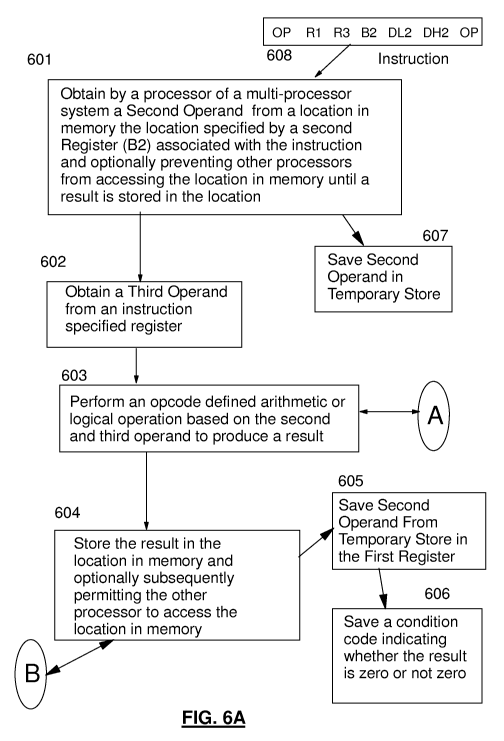
In are enmbodinient., are arthniet.ic/logical- instruction is executed,
wherein he u_nstru.ctioui
comprises are interlocked memory operand, the aritlrnetic/logical instruction
comprisirng an
opcocle field, a first register field specifying a first operand in a first
register, a second
register field specifying a second register the second register specifying
location of a second
operand in memory, and a third register field specifying a third register, the
execution of the
arithmetic/logical instruction comprises: obtaining by a processor.. a semid
operand from a
location in memory specified by the second register, the second operand
consisting of a
value; obtaining a third operand from the third register; performing an opcode
dc-fused
arithmetic operation or a logical operation based on the obtained second
operand and the
obtained third operand to produce a result; storing the produced result in the
location in
memory; and saving the value of the obtained second operand in the first
register, wherein
the value is not changed by executing the instruction.
In an embodiment, a condition code is saved, the condition code indicating the
result is zero
or the result is not zero.
In an embodiment, the opcode defined arithmetic operation is are arithmetic or
logical ADD,
and the opcode defined logical operation is and one of an AND, an .E XCLUSIVIi-
f:plt, or an
OR, and the execution comprises: responsive to the result of the logical
operation being
negatr,we, sawing the condition code indicating the result is negative;
responsive to the result
of the logical operation being positive, saving the condition code indicating
the result is
positive; and responsive to the result of the logical operation being an
o,werflow, saving the
condition code indicating- the result is an overflow.
In an cnmbodinment, operand size is specified by the opcode, wherein one or
more first
opcoÃles specify 32 bit, operands and one or more second opcoÃles specify 64
bit, operands.
In an embodiment, the arithmeiicilogica.l instruction further comprises the
opcode consisting
of two separate opcode fields, a first displacement field and a second
displacement field,
wherein the location in memory is determined by adding contents of the second
register to a
CA 02786045 2012-06-29
WO 2011/160725 PCT/EP2010/067047
7
signed di,splacenrrrrt. value, the signed displacement value comprising a sign
extended value
of the first displacement field concatenated to the second displacement field.
In an enrbodi rent, the e; ecution further comprises: responsive to the opeode
being a first
opcode and the second operand not being on a 32 bit boundary, generating a
specification
exception; and responsive to the opcode being a second opcode and the second
operand not
being on a 64 bit boundary, venerating a specification exception.
In an enrbodinrent, the processor is a processor in a multi-processor system,
and the
execution further comprises: the obtaining the second operand. conipuisirrg
pieventi:ng other
processors of the multi-processor system from accessing the location in memory
between
said obtaining of the second operand and storing a result at the, second
location in memory;
acrd upon said storing the produced result, permitting other processors of the
multi-processor
system to access the location in memory.
The above as well as additional objectives, features, and advantages
embodiments will
become apparent in the f rllowing written description.
BRIEF DESCRIPTION OF THE DRAWINGS
Embodiments of the invention will now be described, by way of example only,
with
reference to the accompanying drawings in which:
FIG. 1A is a diagram depicting an example 1-lost computer sy%sterrr;
FIG. 113 is a diagram depicting an example emulation Host computer systenm;
FIG. 1C is a diagram depicting an example computer system;
FIG. 2 is a diagram depicting an example computer network;
FIG. 3 is a diagram depicting an elements of a computer ,syslier"_ri;
FIGS, 4A-"4C depict detailed elements of a computer system;
FIGS. 5A 5p depict machine instruction format of a computer system;
FIGs. 6A-6B depict an example flow of an embodiment, and
FIG. - depicts an example context switch flow.
CA 02786045 2012-06-29
WO 2011/160725 PCT/EP2010/067047
8
DETAILED DESCRIPTION
.A.ru enrbodinrc:rnt. may be practiced by software (sonieti Ames referred to
Licensed intern_a I
Code, Firmware, - licro-code, Milli-code, Pico-code and the like, any of which
would be
consistent hwith the embodiments). Referring to FIG. IA, software program code
is t ically
accessed by the processor also known as a T (C''entr=al Processing Unit) I of
the system 0
from long-term storage media 7, such as a CD RO N-I drive, tape drive or hard
drive. The
software programs code may be embodied on any of a. variety of known.media,
fbr use, with a
data processing system, such as a diskette, hard drive., or CDROM. -l'he code
may be
{.i E.~ .ibut d ern su h m dia r .n~e~ y> h ,{.istribut d to sees ti:crrr~ t.l
i c c mput~ r memory 2 or
stor=a1ge of one computer :system over a network 10 to other computer systems
for use by
user's of such other svsteins.
Alternatively the program code may be embodied in the memory 2, and accessed
by the
processor I using the processor bus. Such program code includes an operating
system which
controls the function and interaction of the various computer components and
one or more
application Programs. Program code is normally paged from dense storage media
1 i to
high--speed memory 2 whore it is available for processing by the processor 1.
The
techniques and methods for embodying software program. code in memory, on
physical
media, and/or distributing soft ar=e code via net corks are well known and
will not be further
discussed herein. program code, when created and stored on a tangible medium
(including
but not limited to electronic memory modules (IRA N11), flash memory, Compact
Discs (CDs).
DVDs, Magnetic Tape and the like is often referred to as a "computer program
product". The,
computer program product medium is typically readable by a processing circuit
preferably in
a computer system for execution by the processing circuit.
FIG. 1 C illustrates a representative workstation or server hardware system.
'I'he systems 100
of FIG. 1 C comprises a representative cornputer system 141, such as a
personal computer, a
workstation or a server, including optional peripheral devices. The
workstation 141 includes
one or more processors 106 and a bus employed to connect and enable
conualunication
between the processor(s) 106 and the other components of the systenm 141. in
accordance
with known techniques. The bus connects the processor 106 to memory 105 and
long-term
CA 02786045 2012-06-29
WO 2011/160725 PCT/EP2010/067047
9
storage 107 which can include a hard drive (i ncluding my of magnetic Media,
CID, DVD and
Flash Memory for example) or a tape drive for example. The system 1Ã)1 might
also include
a user interlace adapter, which connects the microprocessor 106 via the bus to
one or More
interface devices, such as a keyboard 104, mouse 103, a Printer/scanner 110
arid/or other
interface devices, which can be any user interface device, such as a touch
sensitive screen,
digitized entry pad, etc. 'he Nis also connects a display device 10'., such as
an 1_,C D screen
or monitor,, to the microprocessor 106 via a display adapter.
The system 1Ã)1 may communicate with other computers or networks of
compuruters by way
of a network adapter capable of core municating 108 with a net vork 109.
Example network
adapters are communications channels, token ring, Ethernet or modems.
Alternatively, the
workstation 101 may communicate using a wireless interface, such as a CDPD
(cellular
digital packet data) card. The workstation 101 may be associated with such
other computers
in a Local Area Network (L i) or a Wide Area Network OMAN). or the workstation
101
can be a client in a client/server arrangement with another computer, etc. All
of these
configurations, as well as the appropriate communications hardware and
sollware, are
known in the art.
FIG. 2 illustrates a data. processing network 200 in which embodiments may be
practiced.
The data processing network 200 may include a plurality of individual
networks, such as a
wireless network and a hired network, each o1 hwhich may include a plurality
of individual
workstations 101 201 202 203 244. Additionally, as those skis led in the art
viii l appreciate,
one or more L his may be included, where a LAN may comprise a plurality of
intelligent
Workstations coupled to a host processor.
Still referring to FIG. 2, the, anet,works may also include mainframe compute
r,s or servers,
such as a gateway computer (client server 206) or application server (remote
server/2M
which may access a data. repository and may also be accessed, directly from a
workstation
205"}. A gateway computer 206 serves as a point of entry into each network
207. A gateway
is needed when connecting one networking protocol to another. The gateway-206
may be
preferably coupled to another network (the Internet 207 for example) by means
of a
communications link. The gateway 206 may also be directly coupled to one or
more
CA 02786045 2012-06-29
WO 2011/160725 PCT/EP2010/067047
workstations 101 201 2021 203 204 using a communications link. The gateway
computer
may be implemented utilizing an IBM ; c ~ e rr 3 zSeries z9C <; Server
avadablo, from IBM[
Corp-.
Software programming code is typically accessed by the processor 106 of the
system 101
from long-term storage media 107, such as a C'1)-RON11 drive or hard drive.
The software
programming code, may be embodied on any of a variety of known media for use
with a data
processing system, such as a diskette, hard drive, or CD--ROM, The code may be
distributed
on such media, or may he distributed to users 210 211 from the memory or
storage of one
computer system over a network. to other computer systems for use by users of
such other
systems.
.Alternatively, the programming code iii may be embodied in the memory 105,
and
accessed by the processor 106 using the processor bus. Such programming code,
includes an
operating system which controls the unction and interaction of the carious
computer
components and one or more application programs 11?. Program code is normally
paged
from dense storage media 10- to high-speed memory 105 where it is available
for processing
by the processor 106. The techniques and methods for embodying software
programming
code in ineniorv. on physical media, and/or {istributing software code via net
vorks are well
krioAwn and will not be further discussed herein. Program code, when created
and stored on a
tangible medium (including but not limited to electronic memory modules (RA-
NM), flash
memory, Compact Discs (CDs), D v' Ds, Magnetic "Came and the like is often
referred to as a
"computer program product". The, computer program product medium is typically
readable
by a processing circuit preferably in a computer system for execution by the
processing
circuit.
The cache that is most readily available to the processor (normally faster and
smaller than
other caches of the processor) is the lowest (1_:1 or level orie) cache and mi
iain store (main
memory) is the highest level cache (L3 if there are :"3 leael:s). The lowest
level cache is often
divided into an instruction cache, (LCacbe) holding machine, instructions to
be executed and
a data cache (D--Cache) holding data operands.
CA 02786045 2012-06-29
WO 2011/160725 PCT/EP2010/067047
11
Referring to FIG. 31an exemplary processor embodiment is depicted for
processor 106.
Typically one or ore levels of Cache 303 are employed to buffer e nory blocks
in order
to improve processor perfor niance. The cache 303 is a high speed huff-er hold
n_gg cache lines
ofinernory data that are likely to be used. Typical cache lines are 64, 128 or
256 bytes of
memory data. Separate Caches are often employed for caching instructions than
for caching
data. Cache coherence (synchronization of copies of lines in Memory and the
aches) is
often provided by Various "Snoop" algorithms well known in the art. Main
storage 105 of a
processor system is often referred to as a cache. In a processor system having
4 levels of
cache 303 main storage 105 is sometimes referred to as the level 5 (L5) cache
since it is
typically faster and only holds a portion of the non-volatile storage (DASD,
Tape etc) that is
available to a computer system. Main :storage 105 "caches" pages of data paged
in and out of
the main storage 105 by the Operating system.
A program counter (instruction counter) 311 keeps track of the address of the
current
instruction to be executed, A program counter in a z/Architecture processor is
64 bits and
can be truncated to 31 or 24 bits to support prior addre:ssin ; lit-nits. A
program counter is
typically embodied in a P5W (prograrn_ status word) of a computer such that it
persists
during context switching. Thus, a program in progress, having a program
counter Value, may
be interrupted by, for exa.nrple, the operating system (context s witch from
the program
environment to the Operating system envirorrrtrent). The P5W of the program
maintains the
program counter Val-Lie bile the program is not active, and the program
counter (in the
PSW) of the operating system is used while the operating system is executing,
Typically the
Prop rarrr counter is incremented by an amount equal to the number of bytes of
the current
instruction. RISC (Reduced Instruction Set Computing) instructions are
typically fixed
length while CISC (Complex Instruction Set Computing) instructions are
typically variable
lengrth. Instructions of the IBM zrArch Lecture are CISC instructions having a
length of 2, 4
or 6 bytes. The Program counter 311 is modified by either a context switch
operation or a
Branch takers operation of a Branch instruction for exa. rple. In a context s
,vi_tch operation,
the current program counter value is saved in a program Status Word (1PSW V)
along itfa
other state information about the program being executed (such as condition
codes), and a
new program counter value is loaded pointing to an instruction of a new
program module to
be executed. A branch taken operation is performed in order to permit the
program to make
CA 02786045 2012-06-29
WO 2011/160725 PCT/EP2010/067047
12
decisions or loop within the piogra nm by loading the result. of the Branch I
nst_ructioj_n into the
Program Counter 311.
't'ypically an instruction ]etch Unit 30 5 is employed to fetch instructions
on behalf of the
processor 106. The fetch unit either fetches "next sequential instructions"
target instructions
of Branch Taken instructions, or first instructions of a program following a
context switch.
Modern Instruction fetch units often employ prefetch techniques to
speculatively prof :tch
instructions based on the likelihood that the pr=el~tched in_struà .i_ora_s
might be uased.. For
example, a fetch unit nnay fetch 16 bytes of instruction that includes the
next sequential
in_str=uà .i_on_ and additional bytes of hurther sequential ia_nst_ructioa_ns.
The fetched instructions are then executed by the processor 106. In an
embodiment, the
fetched irrstructiorr(s) are passed to a dispatch runt 306 of the fetch unit.
The dispatch unit
decodes the instruction(s) and forwards information about the decoded
instrcuction(s) to
appropriate units 307 :308 314. J \n e; ecution unit 307 will typical iv
receive ir~fÃ~rrnation
about decoded arithmetic instructions from the instruction fetch unit 305 and
will perform
arithmetic operations on operands according to the opcode of the
iristr=Ãrcti_on. Operands are
provided to the execution unit 307 preferably- either from memory- 105,
ar=c.hitected registers
309 or from an immediate field of the instruction being executed. Resti Its of
the execution,
when stored, are stored either in memory 10-5, registers 309 or in other
machine hardware
(such as control registers, PSW registers and the like).
A processor 106 typically has one or more execution units 307 308 310 for
executing the
function of the instruction. Referring to 11G. 4A, an execution unit 307 may
communicate
with architected general registers 309, a decode/dispatch unit 306 a load
store unit 310 and
other 401 processor units by way of rnter faci:ng logic 407. An Execution unit
307 ma,r
employ several register circuits 403 404 405 to hold information that the
arithmetic logic
unit WAJ) 402 will operate on. The ALC- per lbrnrs auitla_rraeti_c operations
such as add,
subtract, multiply and divide as well as logical function such as and, or and
exei usive-or=
(xorp, rotate and shift. Pref rably the ALU supports specialized operations
that are design
dependent. Other circuits may provide other architected facilities 408
including condition
codes and recovery support logic for example. Typically the result of an LL'
operation is
CA 02786045 2012-06-29
WO 2011/160725 PCT/EP2010/067047
13
held, in an_ output register circuit. 406 which can forward the result to a
variety of other
processing functions. There are many arrangements of processor units, the
present
description is only ilnten_ded, to provide a representative understanding of
one enmbodi: ieiit..
An ADD instruction for example would be executed in an execution unit 307
having
arithmetic and logical furict onahity while a bloating Point instruction for
example would be
executed in a Floating Point Execution having .specialized Floating Point
capability.
Preferably. an execution unit operates on operands ideritif_ed by an
instruction by performing
an opeode defined function on the operands. For example., an ADD instruction
nnay be
executed by an execution unit 307 on operands fb nd in two registers 309
identified by
register fields of the instruction.
The execution unit 307 performs the arithmetic addition on two operands and
stores the
result in a third operand where the third operand may be a third register or
one of the two
source registers. The Execution unit preferably utilizes an Arithmetic Logic l
rr_it (ALU) 402
that is capable ofperfornrin ; a variety of logical functions such as Shift,
Rotate, And, Or and
.XOE_ as well as a variety of algebraic functions incl_udi rg any of add,
subtract, multiply,
divide. Some ALL 's 402 are designed for scalar operations and some for
floating point. Data
may be Big Errdian (Where the least significant byte is at the highest byte
address) or Little
E.ndian (where the least significant byte is at the lowest byte address)
depending on
architecture. The MN-1 z/Architecture is Big Endian. Signed fields may be sign
and
magnitude, l's complement or 2's complement depending on architecture. A 2`s
complement
number is advantageous in that the ALLY does not need to design a subtract
capability since
either a negative valise or a positive value in 2's complement requires only
and addition
within the ALL. Numbers are commonly described in shorthand, where a 12 bit
field defines
an address of a 4,096 byte block and, is commonly described as a 4 Kbyte (Kilo-
byte) block
for example.
Referring to FIG. 413, Branch instruction information for executing a branch
instruction is
typically sent to a branch unit 308 which often employs a branch prediction
algorithm such
as a branch history table 432 to predict the outcome of the branch before
other conditional
operations are complete. The target of the current branch instruction will be
fetched and
CA 02786045 2012-06-29
WO 2011/160725 PCT/EP2010/067047
14
speculatively executed befbre the conditional operations are comriplete.
\k'h_eu the conditi_on_a I
operations are completed the speculatively executed branch instructions are
either completed
or discarded based o n the conditions of the conditional operation and the
speculated
outcome. A typical branch instruction may test condition codes and branch to a
target-
address if the condition codes rncet the branch requirement of the branch
instruction,, a target
address may he calculated based on several numbers including ones found in
register fields
or an immediate field of the instruction for example:. The branch unit 308 may
employ an
..f_;U 426 having a plurality of input register circuits 427 428 429 and, an
output. register
circuit 430. The branch unit 308 may communicate with general registers 309,
decode
dispatch unit 306 or other circuits 425 for example.
The execution of a group of instructions can be interrupted for a variety of
reasons including
a context switch initiated by an operating system, a program exception or
error causing a
context switch" an 1/0 interruption signal causing a context switch or r Multi-
-threading activity
of a plurality of programs (in a multi-threaded environment) for example.
Preferably a
context switch action saves state information about a currently executing
program and then
loads state inib rrr:raa.t.ion_ about an-other program being invoked, State
i:nfbrrraation may be
saved in hardware registers or in n emory for example. State information
preferably
comprises a. program counter value pointing to a next instruction to be
executed, condition
codes, nmrnory translation information and architected register content, A
context. switch
activity can be exercised by hardware circuits, application programs,
operating system
prograrns or firmware code (microcode, pico -code or licensed internal code
(LIC) alone or in
combination.
A processor accesses operands accordin ; to instruction defined methods. The
instruction
may provide an immediate operand using the value of a portion of the
instruction, may
provide one or more register fields explicitly pointing to either general pin-
pose registers or
special purpose registers (floating point, registers fb)r exa.rrrple). The
instruction may utilize
implied registers identified by an opeode field as operands. The instruction m
y utilize
memory locations for operands. A memory location of an operand may be provided
by a
register, an immediate field, or a combination of registers and immediate
field as
exemplified by the z/ Architecttire long displacement facility wherein the
instruction defines
CA 02786045 2012-06-29
WO 2011/160725 PCT/EP2010/067047
a Base register, an Index register and an immediate field (displacermrent
field) that are added
together to provide the address of the operand in memory for example. Location
herein
typically implies a location in_ main- nieimmory (miain storage) unless other
rise indicated.
Referring to FIG. 4C, a processor accesses storage using a Load/Store unit
310. The
Load/Store unit 310 may perform a Load operation by obtaining the address of
the target
operand in memory 303 and loading the operand in a register 309 or another r
nemory 303
location, or may perform a Store operation by obtaining the address of the
target operand in
memory 303 and storing data obtained from a register 309 or another memory 303
location
in the target operand location in memory 303. The Load/Sto.re unit 3 10 irtay
be speculative
and may access r remory in a sequence that is out-of-order relative to
instruction sequence,
however the Load/Store unit 310 must maintain the appearance to programs that
instructions,
were executed in order. A. load/store unit 3 10 may> communicate with general
registers 309,
dc:codeldispatch unit 306, Cache; Memory interface 303 or other elements 455
and comprises
carious register circuits, ALUs 438 and control logic 463 to calculate storage
addresses and
to provide pipeline sequencing to keep operations in order. Some operations r
ray he out of
order but the Load/Store unit provides fi nctionality, to make the out. of
order operations to
appear to the program as having been performed in order as is well known in
the ar=t.
Preferably addresses that an application program "sees" are often r=eferr=ed
to as virtual
addresses. Virtual addresses are sometimes referred to as "logical addresses"
and "effective
addresses". 'T'hese virtual addresses are virtual in that they are redirected
to physical memory
location by one of a variety of Dynamic Address Translation (D AT ) 312
technologies
including, but not limited to sirnplyr prefixing a virtual address with an
offset value,
translating the virtual address via one or more translation tables, the
translation tables
preferably comprising at least a segment table and a page table alone or in
conrbinatiou,
preferably, the segment table having an entry pointing to the page table. In
z/Architecture., a
hierarchy of translation is provided, including a region first .able, a region
second .able, a
region third table, a segment table and an optional page table. The perfonna
ce ot'the
address translation is often improved by utilizing a Translation Look-aside
Buffer (TLB)
which comprises entries snapping a virtual address to an associated p aysical
memory
location. The, entries are created vlicit D AT 312 translates a virtual
address using the
CA 02786045 2012-06-29
WO 2011/160725 PCT/EP2010/067047
16
translation tables. Subsequent use of the virtual address can then utilize the
entryy of the fast
TL B rather than the slow sequential Translation table accesses. 'I'LB content
may be
managed by a variety efreplacerne it algorithms including LR.C- (Least
Recently used).
In the case where the Processor is a processor of a multi-processor system,
each processor
has responsibility to keep shared resources such as I/O, caches, 'I'LBs and
Memory
interlocked for coherency. Typically "snoop" technologies will be utilized in
maintaining
cache coherency. In a snoop envir'onmerit, each cache line may be anaa:rked,
as being in any
one of a shared state, an exclusive state, a changed state, an invalid state
and the like in order
to fb.cili.ate sharing.
I/O units 304 provide the processor with means for attaching to peripheral
devices including
Tape, Disc, Printers, Displays, and networks for example, 1l/C) units are
often presented to the
computer program by software Drivers. In Mainframes such as the z/Series from
IBM,
Chan gel Adapters and Open System Adapters are l/C) units of the Mainframe
that provide
the communications between the operating system and peripheral devices.
The following description from the z/Architecture Principles of Operation
describes an
architectural vicw,~; of a computer system:
STORAGE:
A compotes systersm includes information in main storage, as well l as
addressing, protection,
and reference and change recording. Some aspects of addressing include the
format of
addresses, the concept of address spaces, the various types of addresses, and
the manner in
which one type of address is translated to another type of address. Some of
main storage
includes permanently assigned storage locations. Mann ,s,orage provides the
system with
directly addressable fast-access storage of data. Both data and programs must
be loaded into
main storage (from input devices) before they can be processed.
Main storage may include one or more smaller, faster-access buffer storages,
sometimes
called caches.:' cache is typically physically associated with a T or an I/D
processor.
CA 02786045 2012-06-29
WO 2011/160725 PCT/EP2010/067047
17
The eflbcts, except on performance, of the physical construction and use of Ã
istawt storage
media are generally not observable by the program.
Separate caches may be maintained for instructions and for data operands,
lnfbrmation
within a cache is maintained in contiguous bytes on an integral boundary
called a cache:
block or cache line (or line, for short). A model may provide an 1 XT A. 71' C
ACft
ATTRIBUTE instruction which returns the size of a cache line in bytes. A model
may also
provide P :_l FETCH DATA and PRFF1 TCF DATA RELATIVE b. LONG instructions
which
affects the prefetching of storage into the data or instruction cache or the
releasing of data
from the cache.
Storage is viewed as a long horizontal string of bits. For most operations,
accesses to storage
proceed in a left-to-right sequence. The string of bits is subdivided into
units of eight bits.
An eight-.hit unit is called a byte, hich is the basic building block of all
information
formats. Each byte location in storage is identified by a unique nonnegative
integer, which is
the address of that byte location or, simply, the byte address. Adjacent byte
locations have
consecutive addresses, starting with 0 on the left and proceeding in a 1_ef1
ter right sequence.
Addresses are unsigned binary integers and are 24, 31, or 64 bits.
Information is transmitted between storage and a CPU or a channel subsystem
one byte, or a
group of byts, at a time. Unless otherwise specified. a group of'bytes in
storage is addressed
by the leftmost byte of the groÃap. The number of bytes in the group is either
implied or
explicitly specified by the operation to be perfbrrned. W %hen used in a CPU
operation, a
group of bytes is called a field. Within each group of bytes, bits are
numbered in a 1efl--to--
right sequence.. The leftmost bits are sometimes referred to as the "high-
order" bits and the
rightmost bits as the "lcr- ;-order" bits. Bit numbers are not storage
addresses, ho never. Only,
bytes can be addressed, To operate on individual bits of a byte in storage, it
is necessary to
access the entire byte. The bits in a bye are numbered 0 through 7, from left
to right. The
bits in an address may be numbered 8-31 or 40-63 for 24--bit addresses or 1-
31. or 3 -6:3 for
31-bit addresses; the. are numbered 0-63 for 64-bit addresses. Within any
other fixed-length
format of multiple bytes, the bits making tip the format are consecutively
numbered starting
from 0. For purposes of error detection, and in preferably for correction, one
or more check
CA 02786045 2012-06-29
WO 2011/160725 PCT/EP2010/067047
18
bits may be transmitted ~wwith each byte or with a group of'by>tes. Such check
bits are
generated automatically by the machine and cannot be directly controlled by
the program.
Storage capacities are expressed in number of bytes. When the length of a
storage--operand
field is implied by the operation code of an instr action, the field is said
to have a fixed
length, which can be one, two, four, eight, or sixteen bytes. Larger fields
may be implied for
some instructions. When the length of a storage-operand field is not implied
but is stated
explicitly, the field is said to have a variable: length. Variable:-length
operands can vary, in
to ngrth by ir_rc:r c:rrrcrats of one by e. When inlbrnratiorr is placed in
storage, the contents of
only those byte locations are replaced that are included in the designated
field, even though
the width of the physical path to storage may be greater than the length of
the fluid being
stored.
Certain units of in'thrmation. must be on. an integral boundary in storage. A
boundary is
called integral for a unit of information when its storage address is a
multiple of the length of
the unit in bytes. Special names are given to fields oft, 4, 8, and 16 bytes
on an integral
boundary. A halfword is a group of two consecutive bytes on a two-byte
boundary and is the
basic building block of instructions. A word is a group of.fbur consecutive
bytes on a fimir-
byte boundary. A double -"word is a group of eight consecutive bytes on an
eight-byte
boundary .A quadword is a group of 16 consecutive bytes on a 16-byte boundary.
When
storage addresses designate halfivords, 1Aord,s, doable cords, and quadwords,
the binary
representation of the address contains one, two, three, or four rightmost zero
bits,
respectively. Instructions must be on two-byte integral boundaries. The
storage operands of
most instructions do not have boundary-alignment requirements.
Can models that implement separate caches for instructions and data operands,
a significant
delay may be experienced if the program stores into a. cache line from which
instructions are
subsequently fetched, regardless of whether the store alters the instructions
that are
subsequently fetched.
INSTRUCTIONS:
Typically, operation of the CPI_ is controlled by instructions in storage that
are executed
sequentially, one at a time, left to right in an ascending sequence of storage
addresses. A
CA 02786045 2012-06-29
WO 2011/160725 PCT/EP2010/067047
19
change in the sequential operation may be caused, by brmichi_nng, LOAD PSW,
i_nnterruptions,
SIGNAL PROCESSOR orders, or manual intervention.
PreferaNy an instruction comprises two major parts:
R An operation code (op code',, which specifies the operation to be performed
Optionally, the designation of the operands that participate.
Instruction fb:rnna.ts of the z/Architecture are shown in Ms. 5A--5F. An
instruction can_
simply provide an Opcode 501, or an opcode and a variety of fields including
immediate
operands or regi_,sti r specifiers tors locating operands in registi r,s or
ire memory, The Opcod.e
can indicate to the hardware that implied resources (operands etc.) are to be
used such as one
or more specific general purpose registers (GPRs). Operands can be gouped in
three classes:
operands located in registers, immediate operands, and operands in storage.
Operands may
be either explicitly or implicitly designated. Register operands can be
located in general,
floating--point, access, or control registers, with the type of register
identified by the op
code. The register containing the operand is specified by identifying the
register in a four-lit
held, called the f. field, i n the in,str uction. For soiree instructiorns, an
operand is located in an
implicitly designated register, the register being implied by the op code.
Immediate operands
are ccrrrtained within the in,strruction_, and the 8-bit, 16-bit, or 32 bit
field con_tairuing the
immediate operand is called the I field. {=Operands in storage may have an
implied length; be
specified by a bit mask; be specified by a four-bit or eight--bit length
specification, called the
I-, field, in the instruction; or haw a length specified by the contents of a
general register.
The addresses of operands in storage are specified by means of a format that
uses the
contents of a general register as part of the address. This makes it possible
to:
Specify a complete address by using an abbreviated notation
Perform address manipulation using instructions w,wJii_ch_ ern-ploy general
registers fbr
operands
Modify addresses by program means Without aalteraatiorr of the instruction
stream
Operate independent of the location of data areas by directly using addresses
received from
other programs.
CA 02786045 2012-06-29
WO 2011/160725 PCT/EP2010/067047
The address used to refer to storage either is contained in a register
{esignated by the R field
in the instruction or is calculated from a base address, index, and
displacement, specified by
the B, X, and. F fields, iespecttively, in the instruction. When the `PEA is
in the a.ecÃess-
rcgister mode, a 13 or R field may designate an access register in addition to
being used to
spec if an address. To describe the execution of instr uctioris, operands are
preferably
designated as first and second operands aa'_nd, in so mime cases, third and
fourth operands. In
general, two operands participate in an instruction execution, and the result
replaces the first
operand.
An instruction is one, two, or three halbv%ords in length and must be located
in ,storage on a
halfword boundary. Referring to FiGs. SA - 5F depicting instruction formats,
each
instruction is in one, of 25 basic formats: F 501, 1 502., 503 504, RIE 505
551 552 553
554, RI L 506 507, RIS 555, RR 510, RR-l? 511, RIM: 512 51.3 514, IRS, RS 516
517, RSI
520. RSL 521, RSY 522 523, RX 524, RXE 525. RJ1 F 526. RXY 527, S 530, Sl 531,
SIL
556, Sly 532, SS 533 534 535 5,36 537, SS 1-1 541 . and SSF 542, with three
variations of R R;F,
two of U, ML, RS, and RSA, five of RIE and SS.
The format harries indicate., in general terms, the classes of operands which
participate in the
operation and some details about fields:
RIS denotes a register-and-imm ediate operation and a storage operation.
a RRS denotes a register-and-register operation and a storage operation.
* SIL denotes a storage--arid--immediate operation, with a 1.6-hit i rmmediate
field.
In the 1, REQ., RS, SI, R X, S1, and SS formats, the first byte of an
instruction contains the op
code. In the. E, RRE., RRF, 5, SIL, and SSE fornmats, the first two bytes of
an instruction
contain the op code, except that. EOr sà me instructions in the S fOrnr at.,
the op code is in only
the first byte. In the RI and RIL formats, the op code is in the first byte
and lit positions 12-
15 of an i_nstru coon. In the RIE, RIS, RRS, RSL, RS , RXE, RXF, RXY, and Sly'
t-O.rrraats,
the op code is in the first byte and the sixth byte of an instruction, The
first two bits of the
first or only byte of the op code specify the length and format of the
instruction, as follows:
s:
CA 02786045 2012-06-29
WO 2011/160725 PCT/EP2010/067047
21
In the RR, RRE, RRF, P.P.R., R-X, RXE, RXF, R'., RS, RSY, RSI, RI, P_1E, and
RIL
formats, the contents of the register designated by the RI . field arc called
the first operand.
The register containing the first operand is sometimes referred to as the
"first operand
location," and sometimes as "register R I ". I n the RR_, RRE, RRF and RRR
formats, the R2
field designates the register containing the second operand, and the R2 field
may designate
the same register is P.I. In the RRF, RXF, RS, RSY,RSI, and R11-1 formats, the
use ofthe R.
field depends on the instruction. In the IBS and RSY formats, the R3 field may
instead be an
M3 field specifying a mask. The R field designates a general or access
register In the general
in:str.Ãction:s, a general register in the control instructions, and a
floating-point register or a
general regi,st,cr in the Il_oating--point instructions. For general and
control registers, the
register operand is in bit positions 32-63 of the 64-bit register or occupies
the entire register,
depending on the instruction.
In the I format, the contents of the eight-bit immediate- data field, the I
field of the
instruction, are directly used as the operand. In the S i format, the contents
of the eight-bit
immediate- data field, the 12 field of ill,- instr .Ãction, are used directly
as the second operand.
The BI and DI fields specify the first operand, which is one byte in length.
hi the SIY
format, the operation is the same except that DHI and DLI fields are used
instead of a DI
field, In the P_l format for the instructions ADD HALFWORD IMMEDIATE, CO-NIPAR-
1
I-IAI_FWORD IMMEDIATE, LOAD IIAL1-'WO3R1) IMNIEDIA'.I E. and -MULTIPLY
HALF WORD IMMEDIATE, the contents of the 16-bit 12 field of the instruction
are used
directly as a signed binary integer, and the RI field specifies the first
operand, which is 32 or
64 bits in length, depending on the instruction. For the instruction TEST
LTNDER MASK
(TM1111, T 11-I1-,, --['M LL), the contents of the 12 field are i,ised as a
mask, and the RI
field specifies the first operand, which is 64 bits in length.
For the instructions INSERT IMMEDIATE, ,,k-ND IMMEDIATE,,, OR IMMEDIA'T'E, and
LOAD LOGICAL IMMEDIATE the contents of the 12 field are used, as an unsigned
binary
integer or a logical value, and the RI field specifies the first operand,
which is 64 bits in
length. For the relative-branch instructions in the RI and RSI formats', the
contents of the I6-
bit 12 field are used as a signed binary integer designating a number
ofhalfwords. This
number, when added to the address of the branch instruction, specifies the
branch address.
CA 02786045 2012-06-29
WO 2011/160725 PCT/EP2010/067047
22
For rehatiye-brannch Mstructio ~s in the RIL fb mmat, the I21 field is 32 bits
and is used in the
same way.
For the relati,we--branch instructions in the RI and RSI formats, the contents
of the 16-hit 12
field are used as a signed binary integer designating a number of haifwords.
This number,
When added to the address of the branch instruction, specifies the branch
address. For
relative -branch instructions in the RIL format, the 12 field is 32. bits and
is used in the same
va y. For the P;I E foa rrat instructions COMA PARE. IMMEDIATE AND BRANCH
RE,L NTIVE. and COMPARE LOGICAL IMMEDIATE AND BIA.NCH RELATIVE, the
contents of the 8-bit 12 field is used directly as the second operarnd. For
the P_IE foa rrat
instructions COMPARE I MMEDIA' FE AND BR &NCH (O .II'_ARE IMMEDIATE AND
TRAP., COMPARE LOGICAL IMMEDIATE AND BRANCH, and COMPARE LOGICAL
I MN- 1 M IAI AND TRAP, the contents of the 16- bit 12 field are used directly
as the second
operand. For the E-format instructions COMPARE AND BR-AN-CH RELATIVE,
(.''()MP RE: I> I[~II;I.~E 'l"l=? t _I I3 BRANCH l;ELATIVE, COMPARE LOGICAL
AND
BRANCH REL ATIVE., and COMPARE. LOGICAL IM MEDI _A:_I'E AND BRANCH
RI LATIVE,, the contents of the I6--bit 14 -field are used as a. signed binary
integer
designating a number of half ords that are added to the address of the
instruction to form
the branch address,
For the RIL--format instructions ADD UNMMEDIATE, ADD LOGICAL PNMMEDIATE, ADD
L(_)G[CAL W111-1 SIGNED IMMEDI I I=;, (.'0MPAI; E IMME! IA1 E'., t.,OM PA_I _l
LOGICAL INP4EDI ATE, LOAD IMMEDIATE, and MULTIPLY SINGLE IMMEDIATE,
the contents of the' 2-l it 12 field arc used directly as a the second
operand.
For the RIS-format instxuc ti_on_s, the contents of the 8- bit 1'2 field are
used directlyy as the
second operand. In the SIL format, the contents of the l 6-bit 12 field are
used directly as the
second operand. The BI and DI_ f_elds specify, tl_he first operand, as
described belwww.
In the, RSL, SI, SIL, SSE, and most SS formats, the contents of the general
register
designated by the I-II field are added to the contents of the DI field to form
the first-operand
address. In the RS. RSA', 5, SIY, SS, and SSE formats, the contents of the,
general register
CA 02786045 2012-06-29
WO 2011/160725 PCT/EP2010/067047
23
designated by the B2 field are added to the contents of the D2 .I_elÃi or DH-
H2 and DL2 fields
to form the second-operand address. In the PX, RXE, RXF, and RXY formats, the
contents
of the general registers designated by the X2 and B2 fi_elds are added, to the
contents of the
D2 field or II.I2 and D L2 fields to kwfrr the second-operand address. In the -
IS and I I S
formats, and in one SS format, the contents of the general register designated
by the B4 field
are added to the contents of the 1-D4 field to form the fà urth--operand
address.
In the SS fbr-mat with a single, eight.-Tit length field., for the
instructions, AND (NC),
EXCLUSIVE OR ( C), NIOVE ( VC), MOVE NUMERICS, MOVE ZONES, and OR
(OC), I_, ,speÃ;i ies the number of additional operand bytes to the right of
the byte designated
by the first-operand address. Therefore, the length in bytes of the first
operand is l -256,
corresponding to a length code in L of d-255. Storage results replace the
first operand and
are never stored outside the field specified by the address and length. In
this format, the
second operand has the .same length as the first operand. There are variations
of the
preceding definition that apply to ED T, ]HAT AND N-1 ARK, PACK ASCII, PACT .
UNICODE, TRANSLATE, I I N SLA' E E AN D I ES I , UNPACK ASCII, and l__. NP_ACK
IJNICODI.
In the SS fbrrrraI with length fields, and in the RSL format, Ll specifies the
number of
additional operand bytes to the right of the byte designated by the first-
operand address.
Therefore,, the, length in bytes of the first operand is 1- 16.1 corresponding
to a length code in
Ll of O-l Similarly, L2 specifies the number of additional operand bytes to
the right of the
location designated by the second -operand address Results replace the first
operand and are
never stored outside the field specified by the address and length. If the
first operand is
longer than the second, the second operand is extended on the left with zeros
up to the length
of the first operand. This extension does not modify the second operand in
storage. in the SS
format with two R fields, as used by the MOVE TO PRIMARY, MOVE 'ITS SECONDARY,
and MOVE WITH KEY instructions, the contents of the general register specified
by the RI
field are a 32-bit unsigned value called the true length. The operands are
both of a length
called the effective length. The effective length is equal to the true length
or 256, whichever
is less. ']'he instructions set the condition code to facilitate programming a
loop to move the
total number of bytes specified by the true lerno-th. The SS format with two R
fields is also
1 ?:1
CA 02786045 2012-06-29
WO 2011/160725 PCT/EP2010/067047
24
used to specify a .range of registers and two storage operands for the LOAD
MULTIPLE
DISJOINT instruction and to specify one or two registers and one or too
storage operands
for the PERFORM LOCEKED OPERATION instruct on.
A zero in any of the Bi, B2, X2, or B4 fields indicates the absence of the
corresponding
address component. For the absent corrrponent, a zero is used informing the
intermediate
sum, regardless of the contents of general register O. A displacement of zero
has no special
si_grri #]carice.
Bits 31 and 32 of the current PSW are the addressing- .node bits. Bit 31 is
the extended
addressing mode bit, and bit 32 is the basic-addressing-mode bit. These bits
control the size
of the, effective address produced by address generation. When bits 31 and 32
of the current
PSW both are zeros, the CPU is in the 24 bit addressing mode, and 24-bit
instruction and
operand effective addresses are generated. When bit 31 of the current PSW is
zero and bit 32
is one, the CPU is in the 31 bit addressing erode, and 31-bit instruction and
operand
effective addresses are generated. When bits 31 and 32 of the current PSW are
both one., the
CPU is in the 64-bit addressing .node, and 64--bit, instruct:iorr and operand
effective addresses
are generated. Execution of instructions by the ('P11 involves generation of
the addresses of
instr_-uc.i_ons and operands.
When an instruction is fetched from the location designated by the current
PSW, the
instruction address is increased by the number of bytes in the instruction,
and the instruction
is executed. The same steps are then repeated by using the new value of the
instruction
address to fetch the next. instruction in the sequence. In the 24 bit
addressing mode,
instruction addresses wrap around, with the halfword at instruction address 2'
` - 2 being
follow,%ed, by the half-word at. instruction address P. Thur,s, in the ` 4-
bi_t addressing rrmode, any
carry out of PSW bit position 104, as a result of updating the instruction
address, is lost. In
the 31-bit or 64-Tit addressing mode, irrstrructi_on addresses simi_larly,vi-
ap asroomd, with the
halfword at instruction address 2li - 2 or .,c.r 2, respectively, followed by
the halfs word at
instruction address O. A carr-, out of PSW bit position 97 or 64,
respectively, is lost.
CA 02786045 2012-06-29
WO 2011/160725 PCT/EP2010/067047
An operand address that refers to storage is derived from an intermediate
Value, which either
is contained in a resister designated by an R field in the instruction or is
calculated from the
sum of three binary numbers: base address, index, and displacement. The base
address (B) is
a 64--bit number contained in a general register specified by the program in a
four bit field,
called the B field, in the instruction. Base addresses can be used as a means
of independently
addressing each pr=ogr'ain and data area. In array type calculations, it can
designate the
location of an array, and, in record--t Vi c: processin; it can identify the,
record. The base
address provides for addressing the entire storage. The base address may also
be used for
indexing.
The index (X) is a à 4-Tit number contained in a general register designated
by the program
in a four-bit field, called the X field, in the instruction. It is included
only in the address
specified by the fX--, _XEE,--, and RXY-format instructions. The RX--, ltXE3-,
;Xl'--, and
RXY-format instructions permit double indexing, that is, the index can be used
to provide
the address of an element within an array.
The displacement (D) is a l ` -l it or '20-bit number contained in a field,
called the I) field, in
the instruction. A 12-bit displacement is unsigned and provides for relative
addressing of up
to 4,09-5 bytes beyond the location desi_grrated by the base address..A 20-bit
displacement. is
signed and pro isles for relative addressing of up to 52 4, 287 by>tes beyond
the base address
location or of up to 524,288 b"tes before it. In array-type calculations. the
displacement can
be used to specify one of many items associated with an element. In the
processing of
records, the displacement can be used to identify items within a record. A I2'-
hit
displacement is in bit positions 20- l of instructions of certain formats. In
instructions of
some formats, a second 12-bit displacement also is in the instruction, in bit
positions 36-47.
A 20-bit displacement is in instructions of only the RSY, RXY, or glY format.
In these
inst.ruc .i_on_s, the D field consists of a ICI, (low) field in bit. positions
20-31 and of a DI-I_
(higlr) field in bit positions 32.39. When the long-displacerrment facility is
installed, the
numeric Value of the displacement is formed by appending the contents of the
DH field on
the left a the contents of the Dl_, Field, `hen the Iorrg--displacerrment
tacilityr is not installed,
CA 02786045 2012-06-29
WO 2011/160725 PCT/EP2010/067047
26
the nru ~er-ic value of the displacement is formed by append n_g eight zero
bits on the Jeff of
the contents of the DL field, and the contents of the DH field are ignored.
In forming the intermediate sure, the base address and index are treated as 64
bit binary
integers. A 12-bit displacement is treated as a 12.-hit unsigned binary
integer, and 52 zero
bits are appended on the left. A 20 bit displacement is treated as a 2O bit
signed binary
integer, and 44 bits equal to the sign bit are appended on the left. The three
are added as 64.-
bit binary numbers, ignoring overflow The suns is al rays 64 bits long and is
used as an
intermediate value to form the generated address. The bits of the intermediate
value are
numbered 0-63. A_ zero in any of the B1, B2, .X2, or B4 fields indicates the
absence of the
corresponding address component. For the absent component, a zero is used in
forming the
intermediate sum, regardless of the contents of general register O. A
displacement of zero has
no special significance.
When an instruction description specifies that the contents of a general
register designated
by an R field are used to address an operand in storage, the register contents
are used as the
64-Tit intermediate va.l uu e.
An instruction can designate the same general register both for address
aornpuna.ion_ and as
the location of an. operand. Address computation is completed before
registers, if any, are
changed by the operation. Unless other r ise indicated in an individual
instruction definition,
the generated operand address designates the leftmost byte of an operand in
storage.
The generated operand address is always 64 bits long, and the bits are
numbered 0--6:3. The
manner in which the generated address is obtained from the intermediate, value
depends on
the current addressing anode. ln. the 24-bit addressing mode, bits 0-39 of die
intermediate
value are ignored, bits d.-39 of the generated address are forced to be zeros,
and bits 40.-63 of
the intermediate value become bits 40_63 of the generated address. In the 3 1 -
bit addressing
mode, bits 0.-:32 of the intermediate value are ignored, bits 0.-:32 of the
generated address are
forced to be zero, and bits 33-.63 of the intermediate value become bits 33-63
of the
generated address. In the ltd-bit addressing mode, bits 0.-63 of the
intermediate value become
bits 0-63 of the generated address. Negative values may be used in index and
base.-address
CA 02786045 2012-06-29
WO 2011/160725 PCT/EP2010/067047
27
registers. Bits 0-32 of these values are ignored in the 31--bit. addressing r
ode, and bits 0-39
are ignored in the 24-bit addressing mode.
For branch instructions, the address of the next instruction to be executed
when the branch is
taken is called the branch address. Depending on the branch instruction, the
instruction
format may be RR, _RI?, RX, R; Y, RS, RSY, RSI, RI, RI 3, or RI L, In the RS,
RSA`, RX,
and RXY formats, the branch address is specified by a base address, a
displacement, and, in
the RX and R_XY formats, an index. In these fbrrtm s, the generation of the
intermediate
value follows the same r .rles as for the generation of the operand-address
intermediate value.
In the RR and REF fb.rrnats, the contents of the general register designated
by the R-2) field
are used as the intermediate value from which the branch address is formed.
General register
cannot be designated as containing a branch address. A value of zero in the R2
field causes
the instruction to be executed wit out branching.
The relative-branch instructions are in the RSI, R1, _IE, and RIL formats. In
the RSI, Rl,
and ME formats for the relative--branch instructions, the contents of the 12
field are treated as
a 16-bit signed binary integer designating a .mirrmbe:r of haalfwor=d,s. In
the RIL fbra_ra_at, the
contents of the.. 1 field are treated as a 32-bit signed binary integer
designating a number of
half o.rcls. The branch address is the number of h_aaIfwor=ds designated by
the 12 field added
to the address of the relative--branch instruction.
The 64-bit intermediate value for a relative branch instruction in the RSI,
R[, _IE. or _IL
format is the sum of two addends, with overflow from bit position 0 ignored.
In the RSI, RI,
or RIli format, the first addend is the contents of the 12 field with one zero
bit appended on
the right and 47 bits equal to the sign hit of the contents appended on the
left, except that for
CO 'IPARl AND BRANCH RELATIVE. COMPARE. IMMEDIATE AND BRANCH
REL ' '.l_'IVE, COMPARE LOGICAL AND BRANCH REUVI IVE. and COMPARE
LOGICAL IMMEDI ATE. AND BRANCH RELATIVE, the first addend is the contents of
the 14 field, with bits appended as described above for the 12 field. In the
_I L format, the
first addend is the contents of the 12 field with one zero bit appended on the
right and 31 bits
equal to the sign bit of the contents appended on the left. In all formats,
the second addend is
the 64-bit address of the branch instruction. The address of the branch
instruction is the
CA 02786045 2012-06-29
WO 2011/160725 PCT/EP2010/067047
28
instruction address i ri the PSW before that address is updated to address the
next sequential
instruction, or it is the address of the target of the EXECUTE instruction if
EXECUTE is
used. If EXECUTE is used in the 24-bit. or 3 1-b t addressing tnode, the
address of the branch
instruction is the target address with 40 or 33 zeros, respectively, appended
on the left,
The branch address is always 64 bits long, with the bits numbered O--6:3. The
branch address
replaces bits 6442 of the current PSW. The manner in which the branch address
is
obtained from the intermediate value depends on the addressing mode. For those
branch
instructions which change the addressing mode, the, new addressing mode is
used. In the 24-
bit addressing rrmode, bits 0--39 of the intermediate value are ignored, bits
0--39 of the branch
address are made zeros, and bits 40-63 of the intermediate value become bits
40-63 of the
branch address. In the 31-bit addressing mode, bits 0-32 of the intermediate
value are
ignored, bits 0-32 of the branch address are made zeros, and bits 33--63 of
the intermediate
value become bits 33-6 of the branch address. In the 64-bit addressing mode,
bits 0-63 of
the intermediate sabre become bits 0.63 of the branch address.
For several branch instructions, branching depends on satisfying a specified
condition. When
the condition is not satisfied, the branch is not taken, normal sequential
instruction execution
mnti_nue,s, and the branch address is not used. When a branch is taken, bits 0-
63 of the
branch address replace bits 64--12 of the current I?5W. The branch address is
not used to
access storage as part of the branch operation. A specification exception due
to an odd
branch address and access exceptions due to fetching of the instruction at the
branch location
are not r ecogrnized as part of the branch operation but instead are
recognized as exceptions
associated with the execution of the instruction at the branch location.
A branch instruct on, such as BRA(CI-l AND SAVE, can designate the ,same
general
register for branch address computation and as the location of an operand.
Branch-address
computation is corrrpleted beibrye the remainder of the operation is
per#onrred.
The program-status word (PSWW, described in Chapter 4 "Control" contains
information
required for proper program e;ecution. ']'he PSW is used to control
instruction sequencing
and to hold and indicate the status of the CPU in relation to the program
currently being;
CA 02786045 2012-06-29
WO 2011/160725 PCT/EP2010/067047
29
executed. The active or controlling PSW is called the current PSW. Branch
instructions
perform the functions of decision making, loop control, and subroutine
linkage. A branch
instruction a affects instruction sequencing by introducing a new instruction
address into the
current PSW. ']'he relative-branch instructions with a 16-bit 12 field allow
branching to a
location an offset of up to plus 64K bytes or minus 64K bytes relative to the
location of
the branch instruction, without the use of a base register. The relative-
branch instructions
with a 32.-hit 12 field allow branching to a location at an offset of tip to
plus %l G - 2. bytes or
minus 4G bytes relative to the location of the branch instruction, without the
use of a base
register.
Facilities for decision making are provided by the. BRANCH ON CONDITIO `,
BRANCH
RELATIVE O CONDITION, and BRANCH RELATIVE ON CONDITION LONG
instructions. These instructions inspect a condition code that reflects the
result of a majority
of the arithmetic, logical,, and I/O operations. The condition code, which
consists of two bits,
provides for= four possible condition--code settings: 0, 1, 2, and :3.
The specific meaning of any setting depends on the operation that sets the
condition code.
For example, the condition code reflects such conditions as zero, nonzero,
first operand high,
equal, overflo,v, and subchannel busy. Once set, the condition code remains
unchanged until
modified by an instruction that causes a different condition code to be set.
Loop control can be perfornmed by the use of B_AN01 ON CONDI.1'ION, BRAN01
RELATIVE ON--' CONDITION, and BRANCH RELATIVE ON CONDITION LONG to test
the outcome ofaddress arithmetic and counting operations. For some
particularly frequent
combinations ofarithnmetic and tests, BRANCH ON CO[JN'-C, BRANCH ON INDEX
HIGH,
and BRANCH ON INDEX LOW OR EQUAL are provided, and relative-branch equivalents
of these instructions are also provided. -hese branches, being specialized,
provide increased
performance t-b.r these tasks.
Subroutine linkage when a change of the addressing mode is not required is
provided by the
BKA.NC1-1 A-NI) LIN K- and BR-ANC1I AND SASE instructions. (This discussion of
BRANCH AND SAVE applies also to BRANCH RELATIVE AND SAVE and BRANCH
CA 02786045 2012-06-29
WO 2011/160725 PCT/EP2010/067047
RELATIVE AND SAVE LONG,) Bo di of these instructions permit not only the
'ifltroductioln
of a new instruction address but also the preservation of a return address and
associated
intbrrnati_on. The :return address is the address of the instruction tol low n
g the branch
instruction in storage, except that it is the address of the instruction
folloAino an EX 1-1(-'(-'-' FE
instruction that has the branch instruction as its target.
Both BRANCH AND LINK and BRATN"CH AND SAVE have an RI field. They form a
branch address by means of fields that depend on the instruction, The
operations of the
instructions are summarized as follows:
- In the 24--bit addressing mode, both instructions place the return address
in bit positions 4O-
63 of general register R1 and leave bits O.-3I of that register unchanged.
BRANCH AND
LINK places the instruction--length code for the instruction and also the,
condition code and
program mask from the current P5W in bit positions 32-39 of general register
.I BRAN C,H
,AND SAVE places zeros in those bit positions.
In the .31-bit addressing mode, both instructions place the return address in
bit positions 33-
63 and a one in bit position 32 of general register RI, and they leave hits O-
31 of the register
unchanged,
- In the 64-lit addressing mode, both instructions place the return address in
bit positions 0-
63 of general: register R1.
In any addressing mode, both instructions generate the branch address under
the Control of
the current addressing mode. The instructions place bits 0-63 of the branch
address in bit
positions 64-127 of the P5W. In the RR format, both instructions do not
perform. branching
if the, R2 field of the instruction is zero.
It can be seen that, in the. 24-hit or 31-hit addressing mode, BRANCH AND SAVE
places
the basic addressing- mode ])it, bit 32 of the P5W, in bit position 32 of
general register P:_1.
BRANCH AND LINK does so in the 31-bit addressing mode. The instructions
RIA.NC1
AND SAVE AND SET MODE and BRANCH ADD SET MODE are for use hen a change
of the addressing mode is required during l_irrkage. 'T'he'se instructions
have Rl and R2 fields.
The operations of the. instructions are summarized as follows:
CA 02786045 2012-06-29
WO 2011/160725 PCT/EP2010/067047
31
BRANCH AND SAVE AND SET MODE sets the contents of general register Rl the same
as BRANCH AND SAVE. In addition, the instruction places the extended.-
addressing --mode
bit, bit. 31 of the P5W, in bit, position 63 of the register.
BII._ANCH AND S 3T MODE', if _1 is nonzero, performs as fohlosvs. In the 24.
or 31--bit
mode, it places bit 32 of the P5W in bit position 32 of general register ICI,
and it leaves bits
0-31 and 3.3-63 of the register arichanged. Note that bit 63 of the register
should be zero if
the register contains an instruction address. In the 64-bit mode, the
instruction places bit 31
of the PS W (a one) in bit position 63 of genera I register R L. and it leaves
bits O-62 of the
register unchanged.
Q When R2 is nonzero, both instructions set the addressing; r-node and perform
branching as
follows. Bit 63 of general register R2 is placed in bit position 31 of the
PSW. If bit 63 Is
zero., bit 32 of the register is placed in bit position 3 .1, of the P5W. If
bit 63 is one, PSW bit
32 is set to one. Then the branch address is generated from the contents of
the register,
except with bit 63 of the register treated as a zero, under the control of the
new addressing
mode. The instructions place bits O.63 of the branch address in bit positions
64-127 of the
PS W. Bit 63 of general register R2 remains unchanged and, therefore, may be
one upon
entry to the called program. If R2 is the same as R1, the results in the
{esignated general
register are as specified for the R1 register.
I` J'E1 II.UFFIONS (CONTE= T SW T(H):
The interruption mechanism permil s the CPU to change its state as a result of
conditions
external to the configuration, within the configuration, or wvithin the CPU
itself To permit
fast response to conditions of high priority and immediate recognition of the
type of
condition, interruption conditions are grouped into si: :lasses: e; temal,
input/output,
machine check, program, restart, and supervisor call.
An interruption consists in storing the current P5W as an old P5W, storing-
information
It,
idint.ii ri rg the cause of the interruption, and fetching a new PSW.
Processing resumes as
specified by the new P5W. The old PSW stored on an interruption normally
contains the
address of the instruction that would have, been executed next had the
interruption not
occurred, thus permitting resumption of the interrupted program. For prograrri
and
supervisor--call interruptions, the information stored also contains a code
that identifies tic,
CA 02786045 2012-06-29
WO 2011/160725 PCT/EP2010/067047
32
length of the last-executed instruction, thus permitting the program to
respond to the cause of
the interruption. In the case of some program conditions for which the normal
response is re-
execution of the instruction causing the interru ti_on, the instruction
address directly
identifies the instruction last- executed.
Except for restart, an interruption can occur only when the CPT is in the
operating state, The
restart interruption can occur with the CPU in either the stoned or operating
state:.
Any access exception is generated as part of the execution of the instruction
with which the
exception is associated. An access exception is not generated when the CPU
attempts to
prefetch from an unavailable location or detects some other access-exception
condition, but a
branch instruction or an interruption changes the instruction sequence such
that the
instruction is not executed. Every instruction can cause an access exception
to be generated
because of instruction fetch. Additionally, access exceptions associated with
instruction
execution may occur because of an access to an operand in storage. A r~ access
exception due
to fetching an Instruction is indicated when the first instruction halfivord
cannot be fetched
.without encountering the exception. When the first half-word of the
instruction has no access
exceptions, access exceptions may he indicated for additional halfwords
according to the
instruction length specified by the first two bits of the instruction,
however, when the
operation can be performed i%ithout accessing the second or third halN%ord,s
of the
instruction,, it is unpredictable whether the access exception is indicated
for the unused part.
Since the indication of access exceptions for instruction fetch is cone on to
all instructions,
it is not covered in the individual instruction definitions.
Except where otherwise indicated in the individual instruction description,
the following
rules apply for exceptions associated with an access to an operand location_.
For a fetch-type
operand, access exceptions are necessarily indicated only for that portion of
the operand
which is required ior cor_ra:pletin_g the operation. It is unpredictable
whether access exceptions
are indicated for those portions of a fetch type operand which are not
required for
completing the operation.
CA 02786045 2012-06-29
WO 2011/160725 PCT/EP2010/067047
33
For a sore-type operand, access exceptions are generated, fbr the entire
operand even if the
operation could be completed without the use of the inaccessible part of the
operand. in
situations where the Value of a store-type operand is defined to be
unpredictable, it is
unpredictable whether an access exception is indicated. Wherever an access to
an operand
location can cause an access exception to be generated, the word "access" is
included in the
list ofprogranm exceptions in the description of the instruction. This entry
also indicates
which operand can cause the exception to be generated and whether the
exception is
generated on a fetch or store access to that operand location. Access
exceptions are
generated only for the portion of the operand as defined for each partIC-Ldar
instruct 1011.
An operation exception is generated when the CPU attempts to execute an
instruction with
an in valid operation code. The operation code may be unassigned, or the
instruction with
that operation code may not be installed on the CPU, The operation is
suppressed. The
instruction length code: is 1, 2, or 3. The operation exception is indicated
by a program
interruption code of 0001 hex (or 0081 hex if a concurrent PER event is
indicated).
Sonic models may offer instructions not described in this publication, such as
those provided
for assists or as part of special or custom features. Consequently, operation
codes not
described in this publication do not nccessa:rily cause an operation exception
to be generated.
Further=nmore, these instructions may cause modes of operation to be set up or
may otherwise
alter the machine so as to affect the execution of subsequent instructions. To
avoid causing
such an operation, an instruction with an operation code not described in this
publicatiorn
should be executed only when the specific function associated with the
operation code: is
desired.
.A speciiication exception is generated when any of the fb [lowing is true:
1. A one is introduced into an unassigned bit position of the PSW (that is,
any of bit
positions 0, 2-4, 24--30. or 33-63). This is handled as an early, PSW
specification cxceptiorn.
'. A one is introduced into bit position 12 of the PSW. This is handled as an
early PSW
specification exception.
3. The PSW is invalid in anyr of the following ways: a. Bit 31 of the PSW is
one and bit 32 is
zero. b. Bits 31 and 32 of the PSW are zero., indicating the 24-bit addressing
mode, and bits
CA 02786045 2012-06-29
WO 2011/160725 PCT/EP2010/067047
34
64--i_03 of the P5W are not all zeros. c. Bit 31 of the P5W is zero and bit.
32 is one,
indicating the 3) I -bit addressing mode, and bits 64-96 of the P5W are not
all zeros. This is
handled as an early PSW ,specification exception.
4. The P5W contains an odd instruction address.
5. An operand address does not designate an integral boundary in an
instruction requiring
such integral-boundary designation.
6. An odd-numbered general register is designated by an R field of an
instruction that
requires ra.an even-nurnbe:red registter de,signatioan.
7. A floating-point register other than 0, 1, 4, 5, 8, 9, 12, or 1 3 is
designated for an extended
operand.
8. The multiplier or divisor in decimal arithmetic exceeds 15 digits and
:sign.
9. The length of the first-operand field is less than or equal to the, length
of the second-
operand field in decimal multiplication or divisio.n_
10. Execution of CIPHER MESSAGE, CIPHER MESSAGE W 'ITH CHAINING,
(I() MPl1 T EI l_N T E,RMEDIA-T Ei MESSAGE, DIGEST, COMPUTE LAST MESSAGE
DIGEST, or COMPUTE: MESSAGE AUTHENTICATION CODE is attenmpted; and the
tbn
_nction code in bits ; -63 of general register 0 contain an unassigned or
unin_s .a. _ e
unction code.
1 1 . Execution ofCIPl1ER MESSAGE or CIPHER- ;4 SSAGE WITH CHAINING is
attempted, and the R1 or R2 field designates an odd-numbered register or
general register 0.
12.. Execution of CIPHER 1MIESS AGE. CIPHER MESSAGE WITH CH AIMING,
', }'sll?T_l"I I? I'~l"I'I=;TI[~IT;I= =l 'l"I MESSA(IT, DIGEST or COI\IPI:.YTE
MESSAGE..
AUTHENTICATION CODE, is attempted, and the second operand length is not a
multiple
of the data block size of the designated function. This specification
exception condition does
not apply to the query functions.
13. Execution of CON4PA-P:_l AND FORM CODE WORD is attempted, and general
registers
1, ?, and 3 do not initially contain even values.
32. Execution of COMPARE AND SWAP AND STORE is attei'n-ptc-d and any of the
following conditions exist:
a The, function code specifies an unassigned value.
-The store characteristic specifies an unassigned value.
R The function code is 0, and the first operand is not designated on a word
boundary.
CA 02786045 2012-06-29
WO 2011/160725 PCT/EP2010/067047
Q The function code is I, and the first operand is not designated on a double
word boÃrnda;ry.
a The second operand is not designated on an integral boundary corresponding
to the size of
the store value.
33. Execution of COMPARE LOGICAL LU"NG IJNICODE or M(I) -F: LONG UN ICODE is
attempted, and the contents of -either general register RI + I or R3 + 1 do
not specify an even
number à fbrtes.
3/1. Execution of COMPARE LOGICAL STRING, MOVE STRING or SEARCH STRING
is attempted, and bits 32-55 of general register 0 are not all zeros.
35. Execution of CO APIRESSION CALL is attempted, and bits 48-5 I of general
register 0
have any of the values 0000 and 01 10-1111 binary.
36. Execution of COMPTTE INTER1 IEDIATE MESSAGE DIGEST, CON11PUTE LAST'
MESSAGE DIGEST, or COMPUTE MESSAGE AUTHENTICATION CODE is attempted.
and either of the following is true:
R The R2 ]Field designates an odd-numbered register or general register 0.
Bit 56 of general register 0 is not zero.
37. Execution of CONVERT I-1 FP TO BFP, CON VERT TO FIXED (BR I or FIFP), or
LOAD FP INTEGER- (BFP) is aattemnpted, and the M3 field does not designate a
valid
modifier.
38. Execution of DIVIDE TO INTEGER is attempted, and the M4 field does not
designate a
valid modificr=.
39. Execution of EXECUTE is attempted, and the target address is odd.
40. Execution of EX FIkA(-.'1' STATE is attempted, and the code in bit
positions
56-63 of general register R) is greater than hhera the SNTand-LX--reuse
facility is not
installed or is greater than 5 when the facility is installed.
4 1. Execution of 11- I LEFTMOST ONE is attempted, and the ICI field
designates an
oddriumbered register.
42. Execution of I NVALIDATE DAT TABLE EN'F RY is attempted, and bits 44-5 1
of
general register RZ are not all zero's.
4.3. Execution of LOAD FP(I is attempted, and one or more bits of the second
operand
corresponding to unsupported bits in the FPC register are one.
44. Execution of LOAD E~AGE '1-': I31_:Ii Ii1 '-['I ' . I (I(Ii is attempted
and the 'k,14 field
of the instruction contains any value other than 0000-0100 binary.
CA 02786045 2012-06-29
WO 2011/160725 PCT/EP2010/067047
36
45. Execution of LOAD PSW is attempted and bit 12 of the doubts sword. at. to
,second-
operand address is zero. It is model dependent whether or not this exception
is generated.
46. Execution of MO (ITOP. CALL is aattei pted, and bit positions 8-11 of the
Histruction do
not contain zeros.
47. Execution of MOVE PAGE is attempted', and bit positions 48-51 of general
register 0 do
not contain zeros or bits 52 and 53 of the register are both one.
,l S. Execution of PACK ASCII is attempted, and the L2. field is greater than
31.
49. Execution of PACK U ICODE is att-emp .ed, and the L2 field is greater than
63 or is,
even.
50. Execution of PERFORM FLOATING POINT OPERATION is attempted, bit 32 of
general register P is zero, and one or more fields in bits 33- 63 are invalid
or designate an
uninstalled function.
51. Execution of PER F()Inv-d LOCKED OPERA]]ON is attempted, and any of the
fofowing
is true: F The T bit, bit 55 ofgeneral register Pis zero, and the fanction
code in bits 56-63 of
the register is invalid. b Bits 32-54 of general register 0 are not all zeros.
¾ In the access-
register mode, for function codes that cause use of a parameter list
containing an ALE I. the
R3 field, is zero.
52. Execution of PERFORM TIMIN G FACI h,l'-l'Y FUN CFUNCTION is attempted, and
either of
the fbRowing is true: R Bit 56 of gerreralregister 0 is not zero, m Bits 57--
63 of general register
0 specify an unassigned or uninstalled function code.
53. Execution of PROGRAM TRANSFER or PROGRAM TRANSFER ITH INSTANCE
is attempted, and all of the followirnÃg are true: -The extended a.ddrressing -
rrrdyde bit in the
PSW is zero. - The basic-addressing-mode bit, bit 32. in the general register
designated by
the R2 field of the instruction is zero. ¾ Bits 33-.39 of the instruction
address in the same
register are not all zeros.
54. Execration of RESUME PROGRAM is attempted, and either of the foflowing is
true:
Bits 31, 32, and 64--127 of the PSW field in the second operand are not valid
for placement
in the current P5W. The exception is gi ne:raled if any of the following is
true: - Bits 31 and
32 are both zero and bits 64--iO:3 are not all zeros. --- Bits 31 and 32 are
zero and one,
respectively, and bits 64-96 are not all zeros. - Bits 31 and 32 are one and
zero, respectivel
--- Bit 12-, is one.
R Bits Pm 1 2 of the parameter list are not all zeros.
CA 02786045 2012-06-29
WO 2011/160725 PCT/EP2010/067047
37
55. Execution of SEARCH STRING IJNICODE is attempted, and bits 32-47 of
general
register 0 are not all zeros.
-56. Execution of SET ADDRESS SPACE CONTROL or SET ADDRESS SPACE
CONTROL BAST is attempted, and bits 52 and 53 of the second-operand address
are not
both zeros.
57. Execution ofS1,'I' A.1DDRIiSSE1' Gs' MOf31? (SAM 24) is attempted, and
bits 0-39 of the
un-updated instruction address in the PSW5 bits 64403 of the PSW, are not all
zeros.
-58. Execution of SET ADDRESSING MODE (SANM31) is aiteropted, and bits 0-321
of the
un-updated instruction address in the PSW, bits 64-96 of the PSW, are not all
zeros.
59. Execution of ST CLOCK. PROGRAMMABLE FIELD is aattea_ripteÃ1, and bits 321-
47 of
general register d are not all zeros.
60. Execution of SET FPC is attempted, and one or more bits of the first
operand
corresponding to unsupported bits in the l-'PC register are one,
61. Execution of STORE S STEM INFORMATION is attempted, the function code, in
general register 0 is valid, and either of the fyfowing is true: - Bits 36-55
of general register
0 and bits 32- 47 of general register I are not all zeros. -The second--
operand address is not
aligned on a 4K-byte bouaadary.
62. Execution of ' l'll~ > l '1'E. ' l 'C '1'C ONE or 'FR &NS LATE TWO TO TWO
is
attempted, and the e,71gE. 1 in ge.71e.ra _ iegisL 9r R_I I Ã oes not spccity
an etien 71u"1?er of
bites.
63. Execution of UNPACK ASCII is attempted, and the L1 field is greater than
'31.
64. Execution of UJNPACI . U NICODE. is attersmpted, and the Ll field is
greater than 63 or is
even.
65. : xec: tion of I? PDA'1 E TR E'E is attempted, and the initial contents of
general registers 4
and 5 are not a multiple of 8 in the 24-bit or 31-bit addressing mode or are
not a multiple of
16 iii the 64--bit, addressing mode. The execution of the instruction
identified by the old P5W
is suppressed. However, for early PS W specification exceptions (causes 1-3)
the operation
that introduces the Ere v PSW is com_rrpleL.ed, but an interruption occurs
ir.rnr diatety
thereafter. Preferable, the irnstruction-length code (IL,C) is 1, 2, or."),
indicating the length of
the instruction causing the exception. When the instruction address is odd
(cause 4 on page
6-:33), it is mpredictable whether the ILC is 1, 2, or 3. When the exception
is generated
because of an early PSW specification exception (causes 1-3) and the exception
has been
CA 02786045 2012-06-29
WO 2011/160725 PCT/EP2010/067047
38
introduced by LOAD P5W, LOAD P5W EXTENDED, PROGRAM RETUR:'41, or an
interruption, the ILA;` is 0. When the exception is introduced by SET
ADDRESSING MODE
(S M24, SAN131), the ILC is 1, or it is 2 if SET ADDRESSING MODE was the
target of
When the exception is introduced by SET SYST -All MASK or by STOR-1
THEN OR SYSTEM MASK, the ILC is 2.
Program interruptions are used to report exceptions and events which occur
during execution
of the prograaarn_. A program interruption causes the old. PSW to be stored at
real locations
336-35 1 and a new FISW to be fetched from real locations 464-479. The cause
of the
interruption is identifieÃ1, by the interruption code. The interruption code
is placed at real
locations N2-143, the instruction-length code is placed in bit positions 5 and
6 of the byte at
real location 141 with the rest of the bits set to zeros,, and zeros are
stored at real location
140. For some causes, additional information identifying the reason for the
interruption is
stored at real locations 144.183. If the PER-3 facility is irnstallec , then,
as part of the
program interruption action, the contents of the breaking--event--address
register are placed in
real storage locations 272-279. Except for PER events and the crypto-operation
exception,
the condition causing; the interruption is indicated by a coded value placed
in the rightmost
seven bit positions of the interruption code.. Only one condition at a time
can be indicated.
Bits 0-7 of the interruption code are set to zeros. PER events are indicated
by setting bit 8 of
the interruption code to one. When this is the only condition, bits 0-7 and 9-
15 are also set to
zeros. When a PER event is indicated concurrently with another program
interruption
condition, bit 8 is one, and bits 0-7 and 9-15 are set as for the other
condition. The erypto-
operation exception is indicated by an interruption code of 0119 hex, or 0199
hex if a PER
event is also indicated.
When there is a corresponding mask bit, a. program interruption can occur only
when that,
mask bit is one. The program mask in the l;SW controls four of the exceptions,
the. IEEE
masks in the ERA' register control the IEEE exceptions, bit. 33 in control
register 0 controls
whether SET SYS l EM MASK. causes a special- operation exception, bits 48-63
in control
register 8 control interruptions due to monitor events, and a hierarchy of
masks control
interruptions due to P ?R events. When any controlling, mask bit is zero, the
condition is
ignored., the condition does not remain pending.
CA 02786045 2012-06-29
WO 2011/160725 PCT/EP2010/067047
39
When the new PSW fbr a program interruption has a PSW4b.rm at. error or
cau,ses an
exception to be generated in the process of instruction fetching, a string of
program
interruptions may ocÃ:ur.
Some of the conditions indicated as program exceptions may be generated also
by the
channel subsystem, in which case the exception is indicated in the
suhchannehstatus word or
extended- sta us word.
When a data exception causes a program interr .rption, a data-exception code,
(DXC) is stored
at location 147., and zeros are stored at locations 144--146. The DXC
distinguishes between
the various tyres of data-exception conditions. When the. AFF-P-register
(additional floating-
point registers control bit, bit 45 of control regisier 0, is one, the DXC is
also placed in the
DX ; field of the floating-point-control (FP_'. register. The D.XC' field in.
the FPC register
remains unchanged when any other program exception is reported. The DXC is an
8-bit code
indicating the specific cause of a data exception.
DXC 2 and 3 are mutually exclusive and are of higher priority than. any other
DXC. Thus,
for example, DXC 2 (BF1P instruction) takes precedence over any IEEE
exception; and DXC
3 (DFP instruction) takes precedence over any IEEE exception or simulated IEEE
exception.,
As another example, if the conditions for both DX(' ' _s l l l~ instruction)
and DX(_. I (AF P
register) exist, DXC 3 is reported. When both a specification exception and an
AFP resister
data exception apply, it is unpredictable Which one is reported.
An addressing exception is generated when. the (A)L17; attempts to reference a
main -storage
location that is not available, in the configuration. A main-storage location
is not available in
the configuration when. the location is not installed.. when the storage limit
is not in the
configuration, or when power is off in the storage unit. An address
designating a storage.
location that is .not available in the configuration is referred to as
.invalid, The operation is
suppressed when the address of the instruction is invalid. Similarly, the
operation is
suppressed when the address of the target instruction of EXECUTE is invalid.
Also, the unit
of operation is suppressed when an addressing exception is encountered in.
accessing a table
or table entry. The tables and table entries io which the rule applies are the
dispatchable:-unitr
CA 02786045 2012-06-29
WO 2011/160725 PCT/EP2010/067047
control_ table, the pr ary ASN second- table entry, and entries i the access
list, region first
table, region second table, region third table, segment table, page table,
linkage table,
linkage-= first table, (i_rikage-=secoiid table:, entry table, ASN first.
table. AS:'~1 second table,
authority table, linage stack, and trace table. Addressing exceptions result
in suppression
when they are encountered for references to the, region first table, region
second table, region
third table, segment table, and page table, in both implicit references for
dynamic address
translation and references associated with the execution of LOAD PAGE -TA LE=-
ENTRY
ADDRESS, LOAD RE L ADDRESS. STORE REAL, ADDRESS., and TEST
PROTECTION. Similarly, addressing exceptions for accesses to the
dispatc.hable=-unit
coirtirol table, prin.n l y ASN=-,second-"table: entry, access list, ASN
second table, or authority
table result in suppression when they are encountered in access-register
translation done
either implicitly or as part of LOAD PAGE -T LE-ENTRY DRESS5 LOAD REAL
.ADDRESS, STORE, l l.AL ADDRESS, 'l ES'I AC 1',SS, or'l ES'I PROTl,t.,TH )N.
Except
for some specific instructions whose execution is suppressed, the operation is
terminated for
an operand address that can be translated but designates an unavailable
location. For
termination, changes may occur only to result fields. In this context, the
term "result field'
includes the condition code, r=egister s, and any ,storage locations that. are
prov>i_d.ed, and that
are designated to be changed by the instruction.
The foregoing is useful in urrderstarrding the terrni olog_y> and structure of
one computer
system embodiment. Embodiments not limited to the z/Architecture or to the
description
provided thereof. Embodiments can be advantageously applied to other computer
architectures of other computer manufacturers with the teaching herein.
Referring to FIG. 7, a computer system may be r .anning an Operating System
(OS) 701 and
two or more application programs 7/02 "703 Context switching is employed to
permit an OS
to manage resources used by applications. In one example, an OS 70 1 sets an
interrupt timer
and initiates 704 a context" switch action in order to permit an application
PI:ogr
a period specified by the interrupt timer. The context switch action saves 7O5
State
Information of the OS including the program counter of the OS pointing to a
next OS
instruction to be executed. The context switch action next obtains 705 Mate
Information of
Application Program 1 702 to permit 706 the application program if 1 702. to
start executing
CA 02786045 2012-06-29
WO 2011/160725 PCT/EP2010/067047
41
instructions at the Application Programs obtained current pro am coun_t-er.
Wk' _enn the
interrupt timer expires,, a context switch 704 action is initiated to return
the computer system
to the 0S.
Different processor architectures provide a limited number of general
registers (GRs,
sometimes referred to as general purpose registers, that are explicitly
(andror implicitly)
identified by instructions of the architected instruction scat. IBM
z/architecture and its
predecessor architectures (dating back to the original System 360 circa 1964)
provide 16
general registers GRs) for each central processing unit (C). GRs may be used
by
Processors (central processing .rift (CPU)) instructions as follow,vs:
As a source. operand of an arithmetic or logical operation.
As a target operand of an arithmetic or logical operation.
As a the address of a memory operand (either a base register, index register,
or directly-).
As the length of a memory operand.
Other uses such as providing a function code or other information to and from
an instruction.
Until the introduction of the IBN'I ziArchitecture mainframe in 2000, a
mainframe general
register consisted of 32 bits, with the introduction of z/A_rch_itecture, a
general register
consisted of 64 bits, however, for compatibility reasons, many i/Architecture
instructions
continue to support 32. bits.
Similarly, other architectures, such as the x86 from Intel'x for example,
provide
compatibility modes such that a current machine, having, for example 32 bit
registers,
provide modes for instructions to access only the first 8 bits or 16 bits of
the 32 bit GR.
Even in early IBM System 360 environments, 16 registers (identified by a 4 bit
register field
in an instruction fbr exa.rrrple) proved to be daunting to assembler
programmers and compiler
designers.:' moderately size program could require several base registers to
address code
and data, limiting the number of registers available to hold active variables.
Certain
techniques have been used to address the limited number of registers:
CA 02786045 2012-06-29
WO 2011/160725 PCT/EP2010/067047
42
Program design (as simple as modular progri1.Tn:riiing) helped to Tniiihnize
base-register
overutrhzatÃ011.
Compiler's have used techniques such as register "coloring" to manage the
dynamic
reassignment of registers.
Base register usage can be reduced with the following:
Newer aritlimetie and logi_cal instructions V th il_rrmeE ia. consta~_~ (wi
hi~_i the i ns.T~iction).
Newer instructions with relative-immediate operand addresses.
Newer instructions wih long displacements.
However., there remains constant register pressure when there are more live
variables and
addressing scope than can be accommodated by the number of registers in the ON-
J".
'. rcliitect~ire provides three program--seleetable addressing modes: '?4-, 3i-
-, and 64-hit
addressing. However, for programs that neither require 64-bit values nor
exploit 64-bit
rtmnor=y addressing, having 64-bit GRs is of limited berieft. The f6flo,,,ving
disclosure
describes a technique of exploiting 64-bit registers for programs that do not
generally use
64--bit addressing on variables.
Within this disclosure,, a convention is used where bit positions of registers
are numbered in
ascending order from Ee to right (1Big Endian'). In a 64-bit register, bit 0
(the leftmost bit)
represents the most significant value (2 't and bit 63 (the rightmost bit)
represents the least
significant aahie (2''). The leftmost 32 hits of such a register (hits 0--31)
are called the high
word, and the rightmost 32 bits of the register (bits 32-63) are called the
low word where a
word is 321 bits.
iN----' --------TER------L-_,O----C-------------;D-------ACCESS----------------
---------------------F.ACii-_:-----------iTY-:
-------
in an example /A.rchtectu.ire embodiment, an interlocked.-access facility may
be available
that provides the means by which a load, update, and store operation Can be
performed with
interlocked update in a single instruction (as opposed to using a compare-and-
swap type of
CA 02786045 2012-06-29
WO 2011/160725 PCT/EP2010/067047
43
updat 3. The facility also provides an instruction to attempt to load from two
distinct storage
locations in an interlocked-fetch manner. The facility provides the following
instructions
* LOAD , D ADD
LOAD AND ADD LOGICAL
R LOAD A tD AND
LOAD AND EXCLUSIVE OR
a LOAD AND OR
* LOAD PAIR DISJOINT
I_,O.AD,'STORE ON CONDITIO FACILITY:
In an example z/Architecture embodiment, a loa /stÃ~re~Ã~n-conditi n facility
may provide the
means by which selected operations may be executed only when a condition--code-
-mask field
of the instruction matches the current condition code in the ["SW. The
facility provides the
following instructions.
LOAD ON CONDITION
STORE ON CONDITION
L ISTINC'i' OPERANDS FACILITY:
In an e; aa'nple z/Architecture embodirmmi n_t, a dlst.i_nct-operands facility
may be provide
alternate forms of selected arithmetic and logical instructions in which the
result register
may be different from either of the source registers. The facility provides
alternate forn-ts for
the thlloA%ing instructions.
RADD
ADD IMMEDIA'l t,
ADD LOGICAL
* ADD LOGICAL WITF SIGNED IMMEDIATE
AND
= EXCLUSIVE OR
OR
a SHIFT LEFT SINGLE
= S[-[[l I" LIi.]-' I SINÃ.I LE LOG ICAL
R SHIFT RIGHT SINGLE
CA 02786045 2012-06-29
WO 2011/160725 PCT/EP2010/067047
44
-,SHIFT RIGHT SINGLE LOGICAL
sl__.i RAC"E
* SUBTRACT LOGICAL
POPULATION-COUNT FACILITY
In an e. ample /Architecture embodiment, a population-count facility may
provide the
POPULATION COUNT instruction hwhich provides a count of one bits in each b -t-
oaf a
general register.
STORAGE.OPEP._. D REFERENCES:
For certain special instructions, the fetch references for multiple operands
may appear to be
interlocked against certain accesses by other CPUs and by channel programs.
Such an fetch
reference is called are interlocked-fetch reference, The fetch accesses
associated with an
interlochc:d fetch reference do not necessarily occur one immediately after
the other, but
store accesses by other CPUs may not occur at the same locations as the
interlocked-fetch
reference between the fetch accesses of the interlocked fetch reference. The
storage-operand
fetch reference for the LOADPAI R DISJOINT instruction in ay be an i_r
tcrlocked--iet.ch_
reference. Whether or not LOADIPAIR DISJOINT is able to fetch both operands by-
means
of an interlocked fetch is indicated, by the condition, code. For certain
special instructions,
the update reference is interlocked against certain accesses by other CPUs and
channel
programs. Such an update reference is called an interlockedmupdatc reference:.
The fetch and
store accesses associated with an interlocked--update reference do not
necessarily occur one
immediately after the other, but all store accesses by other CPUs and channel
programs and
the fetch and store accesses associated with interlocked--update references by
other CPUs are
prevented from occurring at the same location between the fetch and the store
accesses of an
interlock_ed update reference.
A multi-Processor system ,night in-corporate various means to interlock
,storage operand
references. One embodiment could have the processor obtaining exclusive
ownership of the
cache line or lines in the system during the references. Another embodiment
hwould require
that the storage accesses are restricted to the same cache line, for example
by repairing that
the operands being accessed from memory are on an integral boundary that would
be within
CA 02786045 2012-06-29
WO 2011/160725 PCT/EP2010/067047
a Cache line. In this case, any 64 (8 byte) operand being accessed ire a 128
byte cache line
is certainly wholly within the cache line if it is on an inte(Fral 64 bit
boundary.
Ell=,d:}(=''_'~_}1;[Jll=?'l"=il lI.IN(=''ES:
For some references, the accesses to all bytes (8 bits) within a half\hvord (2
bytes), word (4
bytes), doubleword (8 bytes*, or quadword (16 bytes) are specified to appear
to be block
concurrent as observed by other CPUs and channel programs. The, halfivord,
word,
doubl_cworde or quad vord is referred to in this section as a block, When a
fetch-~4.y>pe
reference is specified to appear to be concurrent within a block, no store
access to the block
by another CPU or charnel program is permitted during, the time that bytes
contained in the
block are be.inIg fetched. When a store.-t pe reference is specified to appear
to be concurrent
within a block, no access to the block, either fetch or store, is permitted by
another CPU or
channel program during the time that the bytes within the block are being
stored.
The term serializing instruction refers to are instruction which causes one or
more
serialization functions to be performed. The term serializing operation refers
to a unit of
operation within all instruction or to a machine operation such as an i:ntcrru
t:i n hicl_~
causes a serialization function is performed.
Pii.CIF1G 3Pi;RA-N.- 1) SERIALIZATION:
Certain instructions may cause specific-operand serialization to be performed
for an operand
of the irnstruction, As observed by other CE Us and by the channel subsystern,
a specific-
operand-serialization operation consists in completing all conceptually
previous storage
accesses by the CPI_ before a conceptually subsequent accesses to the specific
storage
operand of the instruction may occur. At the completion of an instruction
causinIg specitic-
opera:nd, serialization, the instruc.i_on_'s store is completed as observed by
other CPUs and
channel pro rams. Specific--operand serialization is performed by the
execution of the
f }ll_owingg instructions:
ADD IMMEDIATE (AS_I, AGSI) and ADD I_,(I)GICALWITH SIGNED IMM.EDIA'I E., for
the first operand, when the interlocked-access facility is installed and the
first operand is
aligned on a boundary which is integral to the size of the operand.
CA 02786045 2012-06-29
WO 2011/160725 PCT/EP2010/067047
46
LOAD AND ADD., LOAD AND ADD LOGICAL, LOAD AND AND, LOAD AND
EXC'LL SI-VE OR, LOAD AND OR, for the second operand.
INTERLOCKED tJP1-)JVJ'F`
IBM z/architecture and its predecessor multiprocessor architectures (dating
back to later
System 36Os) have inmplemented certain "interlocked-update" instructions. .n
innterlocked--
update instruction ensures that the CPU on which the instruction executes has
exclusive
access to a memory location from the time the memory is fetched until it is
stored back. This
guarantees that multiple CPUs of a r Multi-processor configuration, attempting
to access the
same location will not observe erroneous results.
The first irite:rlockedmupdate instruction was TEST ND SET (TS), introduced in
S/360
nmultipr ocessing systems. System 370 introduced the COMPARE ANI3 SWAP ((-'S)
and
COMPARE DOUBLE AND SAN' (CDS) instructions. ESAI390 added the COMPARE
A-l l) SWAP A-1 I3 PURGE (CSP) instruction (a specialized form used in virtual
memory
management), z/Architecture added the 64-bit COMPARE AND SWAP (CSG') and
CO 'IPAR_l AND SWAP AND PURGE (CSPG), and the l28-hit COMPARE DOIJIILE
AND SWAP (CDSG) instructions. The z/Architecture long-displace ent facility
added the
COMPARE AND SWAP (CSY) and. COMPARE DOUBLE AND SWAP (CDSY)
instructions. The z/ArchitectÃrre cà mare acrd ss.~rap and stÃyre facility
added the COMPA.lll?
AND SWAP AND STORE innstruction. Mnemonics such as (TS) for the TEST AND SET
instruction are used by assembler programmers to identify the instruction.
']'he assembler
notation is discussed is the z/ tchitecture rcl:.rernce and is not significant
to the teaching of
the present invention.
By using the prior art inierloek_ed-update in_str-uctions t~rc}rÃ: Ãlaborate
lbr-rrms ofsÃiia.lized
access can be effected, including locking protocols, interlocked arithmetic
and logical
operations to memory loà a.tio.n,s, and much more, but at a. cost of
complexity and additional
C KJ cycles. 'T'here is a persistent need for a wider variety of interlocked--
update paradigms
that operate as an atonic unit of operation. Embodiments herein address three
of these
paradigms.
CA 02786045 2012-06-29
WO 2011/160725 PCT/EP2010/067047
47
This disclosure describes ~a o n w sets of instructions that implement
nntertocked update
techniques, and enhancements to a third set of existing, instructions that are
defined to
operate using; interlocked. update when the operands are appropriately
aligned:
Load and Perfor Operation:
'['his group of instructions loads a value from a memory location (the second
operand) into a
general register (the first operand), perfbrnis an arithmetic or boolean
operation on the value
in a. general register (the third operand), and places the result of the
operation back, into the
memory location. The fetch and store of the second operand appears to be a
blocky
concurrent int.erl_ocked update E.o other CT U's.
Load Pair Disjoint:
This group of instructions attempts to load two values from distinct, separate
memory
locations (the first and second operands) into an even odd pair of general
resisters
(designated as the third operand). Whether or not the t two distinct memory
locations are
accessed in an interlocked manner (that is, without one of the values being
changed by
another CPU) is indicated by the condition code.
, O ..ji::OCIR A_T,_ , ,'ITII__SI N,ED] I y' d~I1OI,ATI F_n hh~_m c ,mei_~_E_s
The prior art System :l O introduced several instructions to perform addition
to memory
locations using an immediate Constant in the instruction: ADD IMMEDIATE (ASI,
AGSI)
and ADI3 LOGICAL WITH SIGNED IMMEDIATE ( LSI, ALGSI), As original y defined,
the memory accesses by these: instructions were not interlocked update. When
the
interlocked-update facility is installed and the memory operand for these
instructions is
alined on an integral boundary, the fetch "add itioni:store of the operand is
now defined to be
a block-corrcurren_t interlocked update.
Other architectures implement alternative solutions to this problir.n. For
exanlple, the Intel
Pentium architecture defines a LOCK prefix instruction that affects
interlocked-update for
certain subsequent instructions. However, the locking-prefix technique adds
complexity to
the architecture that is unnecessary. The solution described herein effects
interlocked update
in an atomic unit of operation -- without the need for a prefix instruction.
CA 02786045 2012-06-29
WO 2011/160725 PCT/EP2010/067047
48
INTERLOCK D-STORAGE-ACCESS INSTRUCTIONS:
The following, are examples of Interlocked-Storage Access instructions.
1,{_I AID AN 1) ADD d RSY FORlvMA' l' )
When the instruction is executed by the computer system, the second operand is
added to the
third operand, and the sum is placed at the second--operr and location.
Subsequent v, the
original contents of the second operand (prior to the addition) are placed
unchanged at the
first-operand location, For LAA OpCode, the operands are treated as being, 32-
bit,sigrued,
binary integers. For LAAG OpCode, the operands are treated as being 64 bit
signed binary
integers. The fetch of the second operand for purposes of loading and the
store into the
second-operand location appear to be a block-concurrent interlocked update
reference as
observed by other CPUs. A .spy,cific-operan-.serializatiorn operation is
performed. The
displacement is treated as a 20-bit signed binary integer. ']'he second
operand of LAA must
be designated on a word boundary. The second operand of LAAG must be
designated on a
douhleword boundary. Othemise, a specification exception is generated.
Resulting Condition Code:
0 Result zero; no overflow
l Result less than zero: no overflow
2 Result greater than zero; no overflow
3 Overflow
Program Exceptions:
Access (fetch and store, operand 2)
a Fixed-point overflow
* Operation (if the interlocked access lacilitv is not irastaalled3
* Specification
Programming Notes:
1. Except for the case where the R1 and R3 fields designate the same,
register, general
register R.3 is unchanged.
CA 02786045 2012-06-29
WO 2011/160725 PCT/EP2010/067047
49
2. The operation ofl:,UAD AND ADD, LOAD ANDADD LOGICAL, LOAD AND AND,
LOAD ANDEXCi`LUSI V E OR, and LOAD ,AND OR may be -_,,pr,-ssed as follows.
temp (-- operand---2; opÃ:rand--2 operaa:nd.--21 OP operand--3: operand--I <--
temp; OP
represents the arithmetic or logical operation being performed by the
instruction.
LOAD AND ADD LOGICAL (RSA` l?CiltiMAT)
When the instruction is executed by the computer system. the second operand is
added to the
third operand, and the sum is placed at. the second-operand location.
SubsÃ:quÃ:iitl_y, the
original contents of the second operand (prior to the addition) are placed
unchanged at the
first--operand location. For LAAL OpCode, the operands are treated as being 32-
-bitunsigrned
binary integers. For LAALG OpCode, the operands are treated as being 64.-bit
unsigned
binary integers. The fetch of the second operand for purposes of loading and
the store into
the second-operand location appear to be a block-concurrent interlocked update
reference as
observed by other CPUs. A specific-operand-serializaticon_ operation is
performed. The
displacement is treated is a 2O--bit signed binary integer. The second operand
of LAAL. must
be designated on a word boundary. The second operand of LAALG must be
designated on a
doubieword boundary,. Otherwise, a specification- exception is gerierated.
Resultirrg Condition Code:
4 Result zero; no carry
I Result not zero; no carat
2 Result zero; carry
3 Result not zero; carry
Program Exceptions:
* Access (fetch and store, operand 2)
* Operation (if the interlocked--access facility is not installed)
Q Specification
programming Note: See the programming notes for LOAD AND ADD.
LOAD AND AND (RSY FORMAT)
CA 02786045 2012-06-29
WO 2011/160725 PCT/EP2010/067047
When the instruction is executed by the computer system, the AND of the second
operand
and third operand is placed at the second-operand location. Subsequently, the
original
contents of the second operand(prior to the AND operation) are placed
unchanged at the
first-operand location. For LAN OpCode, the operands are 32 bits. For LANG
OpCode, the
operands are 64 bits. The connective AND is applied to the operands bit by
bit. The contents
of a bit position in the result are set to one if the corresponding bit
positions in both operands
contain ones; otherwise, the result bit is set to zero. The fetch of the
second operand for
purposes of loading and the store into the second-operand location appear to
be a block-
concurrent interlocked update reference as observed by other CPUs. A specific-
operand-
serialization operation is performed. The displacement is treated as a 20-bit
signed binary
integer. The second operand of LAN must be designated on a word boundary. The
second
operand of LANG must be designated on a doubleword boundary. Otherwise, a
specification
exception is generated.
Resulting Condition Code:
0 Result zero
I Result not zero
2--
3
Exceptions:
* Access (fetc}h and store, operand 2)
R Operation (if the interlocked-access facility is not installed)
Specification
piograininin_g Note: See the programming motes for LOAD .AND ADD,
LOAD AND EXCLUSIVE 0R. ( SY FORMAT)
When the instruction is executed by the computer system, the EXCLUSIVE OR of
the
second operand and third operand is placed at the second-operand location.
Subsequently,
the original contents of the second operand (prior to the EXCLUSIVE OR
operation)are
placed unchanged at the first-operand location. For LAX OpCode, the operands
are 32 bits.
CA 02786045 2012-06-29
WO 2011/160725 PCT/EP2010/067047
51
For LAXG OpCode, the operands are 64 bits. The connective exclusive OR is
applied to the
operands bit by bit. The contents of a bit position in the result are set to
one if the bits in the
corresponding bit positions in the two operands are unlike; otherwise, the
result bit is set to
zero. The fetch of the second operand for purposes of loading and the store
into the second-
operand location appear to be a block-concurrent interlocked update reference
as observed
by other CPUs. A specific-operand-serialization operation is performed. The
displacement is
treated as a 20-bit signed binary integer. The second operand of LAX must be
designated on
a word boundary. The second operand of LAXG must be designated on a doubleword
boundary. Otherwise, a specification exception is generated.
Resulting Condition Code:
0 Result zero
I Result not zero
Program l xceptions:
* Access (fetch and store, operand 2)
Q Operation (if the interlocked-access facility is not installed)
Specification
Programming -Note: See the programming rotes for LOAD AND ADD,
LOAD ANI) ORR. (RRSY FORMAT)
When the instruction is executed by the computer system, the OR of the second
operand and
third operand is placed at the second-operand location. Subsequently, the
original contents of
the second operand(prior to the OR operation) are placed unchanged at the
first-operand
location. For LAO OpCode, the operands are 32 bits. For LAOG OpCode, the
operands are
64 bits. The connective OR is applied to the operands bit by bit. The contents
of a bit
position in the result are set to one if the corresponding bit position in one
or both operands
contains a one; otherwise, the result bit is set to zero. The fetch of the
second operand for
purposes of loading and the store into the second-operand location appear to
be a block-
CA 02786045 2012-06-29
WO 2011/160725 PCT/EP2010/067047
52
concurrent interlocked update reference as observed by other CPUs. A specific-
operand-
serialization operation is performed. The displacement is treated as a 20-bit
signed binary
integer. The second operand of LAO must be designated on a word boundary. The
second
operand of LAOG must be designated on a doubleword boundary. Otherwise, a
specification
exception is generated.
Resulting Condition Code:
0 Result zero
I Result not zero
Program is xceptions:
R Access (fetch and store, operand 2)
Operation (if the interlocked-access facility is not installed)
a Specification
Programming -Note: See the programming notes for LOAD AND ADD.
LOAD PAIR 1_)SJOl_N'1' (SS1'' 1-'t.pRMA'l ,)
When the instruction is executed by the computer system, the General register
R3 designates
the even numbered register of an even/odd register pair. The first operand is
placed
unchanged into the even numbered register of the third operand, and the second
operand is
placed unchanged into odd-numbered register of the third operand. The
condition code
indicates whether the first and second operands appear to be fetched by means
of block-
concurrent interlocked fetch. For LPD OpCode, the first and second operands
are words in
storage, and the third operand is in bits 32-63 of general registers R3 and R3
+ 1; bits 0-31 of
the registers are unchanged. For LPDG OpCode, the first and second operands
are
doublewords in storage, and the third operand is in bits 0-63 of general
registers R3 and R3 +
,.When, as observed by other CPUs, the first and second operands appear to be
fetched by
means of block-concurrent interlocked fetch, condition code Ois set. When the
first and
second operands do not appear to be fetched by means of block-concurrent
interlocked
CA 02786045 2012-06-29
WO 2011/160725 PCT/EP2010/067047
53
update, condition code 3 is set. The third operand is loaded regardless of the
condition code.
The displacement of the first and second operands is treated as a 12-bit
unsigned binary
integer. The first and second operands of LPD must be designated on a word
boundary. The
first and second operands of LPDG must be designated on a doubleword boundary.
General
register R3 must designate the even numbered register. Otherwise, a
specification exception
is generated.
Resulting Cornditi_on Code:
0 Register pair loaded by means of interlocked fetch
3 Register pair not loaded by means of interlocked fetch
Program Exceptions:
Access (fetch, operands 1 and 2)
a Operation (if the interlocked-access facility is not installed)
6 Spec ifca.t.io1_I
Progra.r-on.iing Notes:
1. The setting of the condition code is dependent. capon storage accesses by
other (IPUs in the
configuration.
2. When the resulting condition code is 3, the prograrn may branch back to re-
execute the
LOADPAIR DISJOINT instruction. However, after repeated unsuccessful attempts
to attain
an interlocked fetch, the program should use an alternate means of serializing
access to the
storage operands. It is recommended that the program re-execute the LOAD FIAIR
DISJOINT no more than 10 times before branching to the alternate path.
3. The program should be able to accommodate a situation where condition code
0 is never
set.
LO AD/STORE-ON-CONDITION INSTRUCTIONS:
--------------------
The fbllo~w4ng are example Load/Store-on-condition instructions:
LOAD ON CONDITION (RRF, RSY FOR vI T)
CA 02786045 2012-06-29
WO 2011/160725 PCT/EP2010/067047
54
When the instruction is executed by the computer system, the second operand is
placed
unchanged at the first operand location if the condition code has one of the
values specified
by M3; otherwise, the first operand remains unchanged. For LOC and LROC, the
first and
second operands are 32 bits, and for LGOC OpCode and LGROC OpCode, the first
and
second operands are 64 bits. The M3 field is used as a four-bit mask. The four
condition
codes (0, 1, 2, and 3) correspond, left to right, with the four bits of the
mask, as follows:
The current condition code is used to select, the corresponding mask bit, If
the mask bit.
selected by the condition code is one, the load is performed. If the mask bit
selected is zero,
the load is not performed. The displacernent for LOC and LGOC is treated as
a`30--bit signed
binary integer. For LOC and LGOC, when the condition specified by the M3 field
is not met
(that is, the load operation is not performed), it is model dependent whether
an access
exception, or PER zero--address detection is generated for the second operand.
C''ondition Code: The code remains unchanged.
program Exceptions:
* Access (fetch; operand 2 of LOC and LGO ;`)
Q Operation (if the lora.d%'store oaa ~oaaditiora facility is not lnstalled)
Programming is C) Les:
1. When the [x113 field contain zeros, the instruction acts as a NO When the N-
13 field
contains all ones and no exception condition exists, the load opera ion is
always performed.
Hoever, these are not the preferred means of implementing a NCl'P or
unconditional load,
respectively.
2. For LOC and LGOC, when the condition specified by the M3 held is not
mmrret, it is remodel
dependent whether the second operand is brought into the cache.
3. LOAD ON CONDITION provides a function sianilai to that of a separate BRANCH
ON
tDNDIT]ON instruction folio A%ed by a L(i)A.ED instruction, except that LOAD
0_N
CONDITION does not provide an index register. For example, the following Iwo
instruction
sequences are equivalent. On models that implement predictive brarnching, the
combination
of the BRANCH Obi CONDITION and LOAD instructions may perform somewhat better
CA 02786045 2012-06-29
WO 2011/160725 PCT/EP2010/067047
than the LOAD ON CONDITIO ilistnuction ,~Jhean the CPU is able to successfully
predict
the branch condition. However, on models where the CPU is not able to
successfully predict
the branch condition, such as when the condition is more rarndom, the LOAD ON
CON D1'1'1()N instruction may provide significant perfornma.rrce improvement.
ST(-)I;.E. ON CONDITION (1ZSY FORMAT)
When the instruction is executed by the computer system, the first operand is
placed
unchanged at the second operand location if the condition code has one of the
values
specified by M3; otherwise, the second operand remains unchanged. For STOC
OpCode, the
first and second operands are 32 bits, and for STGOC OpCode, the first and
second operands
are64 bits. The M3 field is used as a four-bit mask. The four condition codes
(0, 1, 2, and 3)
correspond, left to right, with the four bits of the mask, as follows: The
current condition
code is used to select the corresponding mask bit. If the mask bit selected by
the condition
code is one, the store is performed. If the mask bit selected is zero, the
store is not
performed. normal instruction sequencing proceeds with the next sequential
instruction. The
displacement is treated as a 20-bit signed binary integer. When the condition
specified by the
M3 field is not met (that is, store operation is not performed), it is model
dependent whether
any or all of the following occur for the second operand: (a) an access
exception is
generated, (b) a PER storage-alteration event is generated, (c) a PER zero-
address-detection
event is generated, or (d) the change bit is set.
Condition Code: The code remains unchmged.
Progranm Exceptions:
a Access (store, operand 2)
* Operation (if the load/store;-on-conditions facility is not ianstalled)
Progra.rnrrnirng Notes:
1, When the M3 field contain zeros, the instruction acts as a _NOR When the M3
field
contains all ones and no exception condition exists, the store operation is
always performed.
However, these are not the preferred means of implementing a NOP or
urnconditiona.I store,
respectivel
CA 02786045 2012-06-29
WO 2011/160725 PCT/EP2010/067047
56
2. When the condition specified by the X43 field is not met, it is model
dependent, whether
the second operand is brought into the cache.
3 STORE ON CONDITION provides a function si_mrti tar= to that of a separate
BRANCH OT T
CON DI'I'ION instruction followed by a S'I'C}RF4 instruction, except that
STORE ON
CONDITION does not provide an index register. For example, the following two
instruction
sequences are equivalent. Can models that implement predictive branching, the
combination
of the BR-,NCH ON CONDITION and STORE instructions may perform somewhat better
than the STORE ON CONDITION instruction when the CPU is able to successfully
predict
the branch condition. However, on models where the CPU is not able to
successfa_ully predict
the branch condition, such as %hen the condition is more random, the STORE
C -NCONDII-7ON instruction may provide significant performance irmmprovcnlent.
INSTRUTCTIONS:
The following are example Distinct-=operand--facility instructions:
A_DI3 (RII., RRE., RRF, RX, RXY I-IM MAT), ADD IMMEDIATE (RIL, MI", l, SlY
FORVIAT)
When the instruction is executed by the computer system, for ADD (A, AG, AGF,
AGFR,
AGR, AR, and AY OpCodes) and for ADD IMMEDIATE (A_FI, AGFI, AGSI, and ASI
OpCodes), the second operand is added to the first operand, and the sum is
placed at the
first-operand location. For ADD (AGRK and ARK) and for ADD PNMMEDIATE(AGHIK
and A-1-11K Op(': odes), the second operand is added to the third operand, and
the sum is
placed at the first operand location.
For ADD (A, AR, ARK, and! f OpCode:s) and for ADD IMNIIEDI `I-'E AF'I
OpCode:sh, the
operands and die ,sun are t:r=eated, as 32--bit, signed. binary integers. For
ADD (AG, A_UR, and
AGRK OpCodes), they are treated as 64-bit signed binary integers.
For ADD (AG li R, AGF OpC'odes) and for ADD ICI M I? I. Ii "C I ;I Cl FI
OpCode), the second
operand is treeaied as a 32-hit signed binary role er, and the first operand
and the sum are
treat d as 64-bit signed binary - integers. For ADD IMMEDIATE ( ASI OpCode),
the second
operand is treated as an 8-bit signed binary integer, and the first operand
and tire: sure are
CA 02786045 2012-06-29
WO 2011/160725 PCT/EP2010/067047
57
treated as 32-bitsigned binary integers, For ADD IMMEDIATE (ADS1 OpCode) e
second
operand is treated as an 8-bit signed binary integer, and the first operand
and the sum are
treated as 64-bit signed binary integers. For ADDIMMI DIATE (AHIK OpCode3, the
first
and third operands are treated as 32-bit signed binary integers, and the
second operand is
treated as a 16-bit signed binary integer. For ADD IMIVIEDIATE (AGHIK OpCodeto
the
first and third operands are treated as 64-hit signed binary integers, and
thesecond operand
is treated as a 16-bitsigned binary integer.
When there is an overflow, the result is obtained by allowing any carry into
the sin-hit
position and ignoring any carry out of the ,sign-bit position, and condition
code 3 is set. If the
fixed-point-o erflow mask is one, a program interruption for fixed-point
overflow occurs.
When the interlocked--access facility is installed and the first operand of
ADD IMME'DIA'-1'E
(ASI, AGSI) is aligned on an integral boundary corresponding to its size,
their the fetch and
store of the first operand are perfor=med as an interlocked update Is observed
by other C ?Us,
and a specific-operarnd--serialization operation is performed. When the
interlocked--access
facility is not installed, or when the first operand of ADD I: INT DIA_TI
(ASI, AGSI) is not
aligned on an integral boundary corresponding to its size, then the fetch and
store of the
operand are not performed as an interlocked update.
The displacement for A is treated as a I2--bitunsigned binary integer. The
displacement for
AY,AG; AGF, AGS:1 and AST, is treated as a 20-hit signed binary integer.
Resulting Condition Code:
0 Result zero. no overflow
I Result less than zero; no overflow
2 Result greater than zero:, no overflow
3 Overflow
Program Exceptions:
Access (fetch and store, operand I of AGSI and AS:I ors lye; fetch, operand 2
of A, AY, AG,
and AGF only)
CA 02786045 2012-06-29
WO 2011/160725 PCT/EP2010/067047
58
Q e point, overflow
Operation (AY, if the long-displacement facility is not installed; AF I and
AGFl, if the
extendedirn nediate facility is not installed, AGSI and ASI, if the general-
instruà .i_on_s--
extension facility is not installed; A R -K, AGR K, Af III, and A(-II-IIK_, if
the distinct-operands
facility is not installed)
Program mming Notes:
1. Accesses to the first, operand of ADD IMMEDIATE (AGSI and ASI) consist in
fetching a
firstoperand from storage and subsequently storing the updated value. When the
interlocked-
access #hcility is not installed, or when the first operand is not aligned on
an integral
boundary corresponding to its size, the fetch and store accesses to the first
operand do not
necessarily occur one immediately after the other. Under such conditions, ADD
I MMEDIA I' 1 (A.GSI and AS I) cannot be safely used to update a location in
storage if the
possibility exists that another CPU or the channel subsystem may also be
updating the
location. When the interlocked-access facility is installed and the first
operand is aligned on
an integral boundary corresponding to its size, the operand is accessed using
a block
concurrent interlocked update.
2. For certain programming languages which i nore overflow conditions on
arithmetic
operations, the settinng of condition code 3 obscures the sign of the resuIt..
However, f-br ADD
INI META ATE,, the sign of the 12 field (which is l- nosvn at the time of code
generation') may
be used in setting a branch mask which will accurately determine the resulting
sign.
ADD LOGICAL (RR., RRE, RX, RXY Format) ADD LOGICAL IMMEDIATE (RIL
Format)
When the instruction is executed by the computer system, for ADD LOGICAL (AL,
ALG,
ALOE, , LGER, ALGR, ALR, and ALY OpCodes) and for ADD LOGICAL IMNT DIAT
9ALCIFI and ALFI OpCodes;, the second operand is added to the first operand,
and the sum
is placed at the firs topÃ:rand location.
For ADD LOGICAL (ALGRK and ALRK OpCodes\\ the second operand is added to the
third operand, and the sum is placed at the first-operand location. For ADD
LOGICAL (AL,
ALR, ALIT, and ALY OpCodes) and for ADD LOGICAL IMMEDIATE ( LFI OpCode),
CA 02786045 2012-06-29
WO 2011/160725 PCT/EP2010/067047
59
the operands and the sum are treated as 32-bit unsigned binary integers, For
ADD
LOGICAL (ALG, A FR,, and ALGRK OpCodes), they are treated as 64-bit unsigned
binary
integers. For ADD LOGICAL (: I-:Cil='R9 LG OpCodes) and for ADD LOGICAL
I MN- 11? CIA I11 (A LG I:1 OpCode;i, the second operand is treated as a 2 hit
unsigned binary
integer, and the first operand and the sum are treated as 64-bit unsigned
binary integers.
The displacement for A.L is treated as a I2 hit unsigned binary integer. The
displacement for
ALY, ALG, and A LGF is treated as a 20-bit signed binary iiltegcr.
Resulting Condition Code:
0 Result zero; no carry
I Result not zero; no carry 2. Result zero; Carry
3 Result not zero; carry
Program Exceptions:
a Access (fetch, operand 2 of AL, 'SLY, ALG, and ALGF only;)
* Operation (ALY, if the long--d.isplacemnent flicility is not instaalled ALFI
and , LGRI, if the
extended immediate facility is not installed; ALRK and ALGRK, if the distinct-
operands
facility is not installed)
ADD LOGICAL WITH SIGNED IM NIEDI ATE (STY, RIE, Format)
When the instruction is executed by the computer system, for ALÃ SI OpCodc and
ALSI
OpCodc, the second operand is added to the first operand, and the sum is
placed at the
firstoperand location. For AL II-ISIIC and f'4I-:I-ISIK, {)pCodes the second
operand is added to
the third operand, and the sure is placed at the first-operand location. For
ALS I OpCode, the
first operand and the sum are treated as 32 -bit unsigned binary integer's.
For .AI:GSI
OpCodes, the first operand and the sum are treated as 64-bit unsigned binary
integers. For
both ALSI and ALGSI, the second operand is treated as an 8-bit signed binary
integer. For
Af,I-1S IK Op(_ ode, the first and third operands are treated as .32--bit
unsigned binary integers.
For :GHSIK OpCode, the first and third operands are treated as 64-bit unsigned
binary
integers. For both AL II-ISIK and A. LHSIK, the second operand is treated as a
16-bit signed
binar integer.
CA 02786045 2012-06-29
WO 2011/160725 PCT/EP2010/067047
When the interlocked-access facility is installed and the first, operand is
alignied on an
inte.(:-ral boundary corresponding- to its size, the operand is accessed using
a block concurrent
interlocked update. For ALGSI and ALSI, the second operand is added to the
first operand,
and the sum is placed at the first operand location. ]"or t LGHSIK and ALHSIK,
the second
operand is added to the third operand, and the sum is placed at the first-
operand location. For
ALSI, the first operand and the suer are treated as :32-bit unsigned binary
integers. 1= or
ALGSI, the first operand and the sum are treated as 64-bitunsigned binary
integers. For both
ALSI and ALGSI, the second operand is treated as an 8-bit signed binary
integer. For
ALHSIK, the first and third operands are treated as 32-hit unsigned binary
integers. For
ALGHSIK, the first and third, operands are treated as 64--bitunsigned binary
integers. For
both ALGLHSI K and ALHSI K, the second operand is treated as a 16.bitsigned
binary integer.
When the interlocked-access facility is installed and the first operand is
aligned on an
integral boundary corresponding to its size, then the fetch and store of the
first operand is
performed as an interlocked update as observed by other CPUs, and a specific
operand-
serializ.ation operation is performed. When the interlocked-access facility is
not installed, or
when the first operand of ADD LOGICAL WITHSIGNED IN MEDIATE (ALSI, ALGSI) is
not aligned on an integral boundary corresponding to its size, then the teach
and, store of the
operand are not performed as an interlocked update. When the second operand
contains a
negative value, the condition code is set as though a SUBTRACTLOGICAL
operation was
performed. Condition codeÃl is never set when the second operand is negative.
']'he
displacement is treated as a.20-bit signed binary integer.
Resulting Condition Code:
4 Result zero; no carry
l Result not zero;, no Carry
Result zero; carry
3 Result not zero; carry
ANI) (RR, RRE, RRF, RX, RXY, SI, SlY, SS I'(3ELTVMAll )
When the instruction is executed by the computer system, for N, NC, NG, NGR,
NI, NIY
NNR, and NY OpCodes, the AND of the first and second operands is placed at the
first
operand location. For NGRK and IRKS the AND of the second and third operands
is placed
CA 02786045 2012-06-29
WO 2011/160725 PCT/EP2010/067047
61
at the first operand locatiora_. The connective AND is applied to H'ie
operands bit. by bit. The
contents of a bit position in the result are set to one If the corresponding
bit positions in both
operands contain ones; otherww%ise, the, r:=esualt, bit. is set to zero. For
AND (NC OpCode), each
operand is processed left to right. When the operands overlap, the result is
obtained as if the
operands were processed one byte at a time and each result byte were stored
immediately
after fetching the necessary operand bytes. For . AN ( (NI and l ` Op ode
C the first
operand is one, byte in length, and only one byte is stored. For AND (N, NR,
NRK, and NY),
the operands are 32bits, and for AND (NG, SCR, and NGR _ OpCodes), they are 64
hits.
The displacements for N, -N-I, and both operands of NC are treated as i 2-bit
unsigned binary
integers. The displacement for :- , MY, and :' G is treated as a'20--bid,
sigrned binary integer,
Resulting Condition Code:
Ã) Result zero
I Result not zero
Program Exceptions:
Q Access (et.ch, operand 2, :'~1, NY, NG, and NC; ietch and sttor=e, operand
1, N I, MY, arid
NC)
Operation (NIY and NY, if the long-displacement facility is not installed:
NGRK and
.NR-, if the distinct operands facility is not installed)
EXCLUSIVE OR (RR, RRE, !RRF, RX, RIY, SI, SlY, SS FOlwAT)
When the instruction is executed by the computer system, for X, XC, XG, _XC R,
Xi, XIY,
XR., and XY OpCod:,vs, the EXCLUSIVE OR of the first, and second operands is
placed at
the first-operand location. For XGRK and XRK OpCodws, the EXCLUSIVE OR of the
second and third operands is placed at the first.-operand locat.ion_. The
connective
EXCLUSIVE OR is applied to the operands bit by bit. The contents of a bit
position in the
result are set to one if the bits in the corresponding hit positions in the,
two operands are
unlike; otherwise, the result bit is set to zero, For EXCLUSIVE OR (XC COp(-
`odws), each
operand is processed left to right. When the, operands overlap, the result is
obtained as if the
CA 02786045 2012-06-29
WO 2011/160725 PCT/EP2010/067047
62
operands were processed one byte at a time and each result byte were stored
.nn diately
after fetchin(:- the necessary operand bytes. For EXCLUSIVE OR (XI, MY OpCodws
the
first operand is one byte in length, and only one byte is stored. For
EXCLUSIVE OR (X,
.XR, XRK, and XV OpCodws), the operands are 32 bits, and for EXCLUSIVE OR
9, C S C1I , and XGR_K OpCodws), they are 6/1 bits. The displacements for X,
XI, and both
operands of XC are treated as 1 2-bit unsigned binary integers. ']'he
displacement for .XY,
XIY, and XC is treated as a20-bit signed binary integer.
Resulting- Condition Code:
0 Result zero
l Result not zero
3 Progr arn Exceptions:
a Access (fetch, operand 2, X, XV, XCi, and XC; fetch and store, operand 1,
XI, XIV, and
XC)
Operation (MY and XV, if the long-displacement facility is not installed; XGRK
and
XI K, if the distinct operands facility is not installed)
Progr amm_ing Notes:
1.-
2. EXCLUSIVE OR may be used to invert a bit, an operation particularly useful
in testing
and setting programmed binary switches.
.3. A field I XCLIJS. VE-()Red with itself becomes allzeros.4. For E.X
'!LUSIVE OR (XR or
XGR), the sequence A EXCl= USI VE-O R B, B EXCLUSIVE-OR A, AEXCLUSI \'E-OR B
results in the exchange of the contents of A_ and B rith_out, the use o fan
additional gÃileral
regi:ster.5. Accesses to the first operand of EXCLUSIVE OR(M) and EXCLUSIVE OR
(XC) consist in fetching a frrst--operand byte from storage and, subsequently
storing the
updated value. These fetch and store accesses to a particular byte do not
necessari y occur
one immediately after the other. Thus, EXCLUSIVE OR carrot be safely used to
update a
location in storage if the passibility exists that another C PU or a channel
pro-gram may also
be updating the location.
CA 02786045 2012-06-29
WO 2011/160725 PCT/EP2010/067047
63
OR (R-R-, RRE, RRF, RSA, RXY, S1, Sly', SS FORMAT)
When the instruction is executed by the computer system, for 0, Of', 0Ci, OCR,
01, 01Y,
OR., and OY OpCodes, the OR of the first and second operands is placed at
tl_re first operand
location. ]"or OGRK and OR_:, the OR of the second and third operands is
placed at the first-
operand location. The connective OR is applied to the operands bit by bit.
The, contents of a
lit position in the result are set to one if the corresponding bit position in
one or both
operands contains a one., otherwise, the result bit is set to zero. For OR (OC
0pCode), each
operand, is processed left to right. When the operands overlap, the result is
obtained as if the
operands were processed one byte at a time and each result byte were stored
immediately
after fetching the necessary operand bytes. For OR ('01, OIY OpCodes), the
first operand is
one bbyte in length, and only one. byte is stored. For OR (0, OR, ORK, and OY
OpCodes),
the operands are 32bits, and for OR (0G. OGR, and OGRK OpCodes), they are
6%Ibits.The
displacements for 0, 01, and both operands of 0I:' are treated as 12-bit
unsigned binary
integers. The displacement for OY, OIY, and OG is treated as a20-bit signed
binary integer.
Resulting; Condition Code:
0 Result zero
I Result not zero
SHIl 'I' SINGLE (RS, S FOR[IIIf'4.'I')
When the instruction is executed by the, computer system, for SL A OpCode, the
31-bit
numeric part of the signed first operand is shifted left the number of bits
specified by the
second-operand address, and the result is placed at the first-operand
location. Bits 0-31 of
general registerR_I remain unchanged. For SL.AK OpCode, the 3l-bit numeric
part. of the
signed third operand is shifted left the number of bits specified by the
second-operand
address, and the result, with the sign bit. of the third operand appended on
its left, is placed at.
the first-operand location. Bits 0-31 of general register R l remain
unchanged, and the third
operand remains unchanged in general register R3. For SLAG OpCode, the 63-bit
n mreric
part of the signed third operand is shifted left the number of bits specified
by the second--
operand address., and the result, with the sign bit of the third operand
appended on its left, is
CA 02786045 2012-06-29
WO 2011/160725 PCT/EP2010/067047
64
Placed at the first-operanÃl location. The third operand remains unchanged i n
get_neraal register
R3.The :seeonnd-operand address is not used to address data; its rightmost six
bits indicate the
number of bit positions to be shifted. The remainder of the address is
igrnored. For SLA
OpCode, the first operand is treated as a 32-hitsigned binary integer in bit
positions 2.-6:3 of
general register R1. The sign of the first operand remains unchanged. All 31
numeric bits of
the operand participate in the left shift, For S _,AK, the first and third
operands are treated
as32-bit signed binary integers in bit positions 32-63 of general registers R1
and R3,
respectively. The sign of the first operand is set. eÃtu.a I to the sign ofthe
third operand. A 113 1
numeric bits of the third operand participate in the left shift. For SLAG, the
first and third
operands are treated as64-bit ,signed binary integers in bit positions 0--63
of generaI registers
R I and R3, respectively. The sign of the first operand is set equal to the
sign of the third
operand. All 63 numeric bits of the third operand participate in the left
shift, For SL A.,
SLAG, or SI AI :, zeros are supplied to the vacated bit positions on the
right. Iforie or more
bits unlike the sign bit are shifted out of bit position 33, for SLR or SL AK,
or bit position
I ,tor SLAG, an overflow occurs, and condition code 3 is set. If the #i~ eÃ
point Ã~ erll~s
mask lit is one, a program interruption for fixed--point overflow occurs.
Resulting C onditiÃan Code:
0 Result zero; no overflow
I Result less than Zero; no overflow
. 2Result greater' than zero; no overflow
3 (I)vverfà A
Fixed -point overflow
Operation (SLAK_, if the distinct-operands facility is not installed)
SHIFT LEFT SINGLE LOGCA1. (RS. RSY FORMAT)
When the instruction is executed by the computer system, for SLL OpC'ode, the
32 hit first
operand is shifted left the number of bits specified by the second-operand
address, and the
result is placed at the first-operand location. Bits 0--31 of general register
IM renraiii
unchanged. For SLLK, the 32.-bit third operand is shifted left the number of
bits specified by
the second-operand add-ress, and the result is placed at the first-operand
location. Bits Ãl.31
of general register R1 drain unchanged, and the third operand remains
unchanged in
CA 02786045 2012-06-29
WO 2011/160725 PCT/EP2010/067047
general register R3. For SIJ_,G OpCode, the 64-bit third operand i,s ,shifed
left the number of
bits specified by the second-operand address, and the result is placed at the
first-operand
location. The third operand remains unchanged in general register R3.The
secornd-operand
address is not used to address data, its rightmost six bits indicate the
number of bit positions
to be shifted. The remainder of the address is ignored. For SLL, the first
operand is in bit
positions 32--63 of general register I. A H 32 bits of the operand participate
in the left shift.
For SLLK, the first and third operands are in tit positions 32-63 of general
registers Ri and
R3, respectively. Al132 bits of the third operaa:nd participate in the let
shift. For SLLG, the
first and third operands are in hit po:sitionsll--63 of general registers It I
and R3, respectively.
"L 64 bits of the third operand participate in the leff shift, For SA_:, SLLG,
or S1 1K
OpCodes, zeros are supplied to the vacated bit positions on the right,
Condition 'ode: The code remains unchanged.
Program Exceptions:
a Operation (SLLK, if the distinct-operands facility is not installed)
SHIFT RIGHT' SINGLE (RS, RSA FORMA-
W"herr the instruction ,s executed by the con~prater system, fbr SRA OpC;ode,,
the 31-b t
numeric part of the signed first operand is shifted right the number of hits
specified by the
second-operand address, and the result is placed at the first-operand
location. Bits 0-3.1, of
general register IM remain unchanged. ]"or SLAB, OpCode,, the :31--bit numeric
part of the
signed third operand is shifted right the number of bits specified by the
second-operand
address, and the result, with the sign bit of the third operand appended on
its left, is placed at
the first-operand location. Bits 0-32 of general register R 1 remain
unchanged. For SHIFT
RIGHT SINGLE (SR-AG OpCode, ), the 63--bitrnumeric part of the signed third
operand, is
shifted right the number of bits specified by the second-op .rand address, and
the result, with
the sign bit of the third operand appended on its left, is planed at the first-
operand location,
The third operand remains unchanged in general register R3.The second-operand
address is
not used to address data-, its rightmost six bits indicate the number of bit
positions to be
shifted, The remainder of the address is ignored. For SRA, The first operand
is treated as a
32 bitsigned binary integer in bit positions 32-63 of general register RI. The
sign of the first
CA 02786045 2012-06-29
WO 2011/160725 PCT/EP2010/067047
66
operand remains unchanged. A-11 31 numeric bits of the operand participate in
the right shift.
For SRAK, the first and third operands are treated as32 bit signed binary
integers in bit
positions 32-63 of general registers R I and R3, respectively, The sign of the
first. operand is
set equal to the sign of the third operand, A11 .31 numeric bits of the third
operand participate
in the right shift. For SRAG, the first and third operands are treated
as64Tbit signed binary
integers in lit positions 4--63 of genera registers t_1 and R3, respectively.
The sign of the
first operand is set equal to the sign of the third operand. All 63 numeric
bits of the third
opera:nd, participate in the right shift. For SRA, SR_AG, or SR, K, bits
shifted, out of bit
position63 are not inspected and are lost. Bits equal to the sign are supplied
to the vacated bit
positions on the left.
Resulting Condition Code:
Ã1 Result zero
I Result less than zero
2 Result greater than zero
Program Exceptions:
Q Operation (SRAK, if the distinct-operands facility is not installed)
Programming Notes:
1. A right shift of one bit position is equivalent to division by 2 with
rounding downward.
When an even number is shifted right one position, the result is equivalent to
dividing the
number by 2.When an odd number is ,shifted right one position, the result is
equivalent to
dividing the next lower number by 2. For e xarnple, -5 shifted right by one
bit position yields
-1-2,, whereas --5 yields-3.
2. For SHIFT RIGHT SINGLE (SRA and SRAK),shift amounts from 31 to 63 cause the
entire numeric part to be shifted out of the r:egi_ster, leaving a. result of -
-I or zero, depending
on whether or not the initial contents were negative. For SI-111 -1' RIG-IT
SINGLE (S1;AG), a
shift amount of 63 causes the same effect.
SHIFT RIGHT SINGLE LOGICAL (RS, RSY FORMAT)
CA 02786045 2012-06-29
WO 2011/160725 PCT/EP2010/067047
67
When the instruction is exeÃ:uted by the conrputÃ:r system, fbr SRL OpCodÃ:,,
the 32-l_rit first
operand is shifted right the number of bits specified by the second-operand
address, and the
result is placed at the first-operand location. Bits 0-3 i of general register
R_1 remain
unchanged, l`or SRLK (_)pC'ode,, the 32-bit third operand is shifted right the
number of bits
specified by the second-operand address, and the result is placed at the list-
operand
location. Bits 0-31 of general register RI remain unchanged, and the third
operand remains
unchanged in general register R3. For SRLG OpCodc:,, the 64--bit third operand
is shifted
right the number of bits specified by the second-operand, address, and the
r:=esrrlt. is placed at
the first-operand location. The third operand remains unchanged in general
register R3.-l-'hc
second-operand address is not used to address data; its rightmost six bits
Iridicatc- the number
of bit positions to be shifted. The remainder of the address is i pored. For
SRL, the first
operand is in bit positions 32-6 of general register RI, All 32 bits of the
operand participate
in the right shift. For SRLK, the first and third operands are in bit posit
ons32--6:3 of general
registers RI and R3, respectively. All 32.. bits of the third operand
participate in the right
shift. For SR 1_:G, the first and third operands are in bit pos tionsO-63 of
general registers RI
and R3, respectively. All 64 bits of the third operand participate in the
right shift. For SRL,
SRLG.. or SRLK9 bits shifted out. of ])it po,sitior163 are not inspected and
are lost. Zeros arc-
supplicd to the vacated bit positions on the left.
Condition Code: The code remains unchanged.
Program Exceptions:
R Operation (SRLK, if the distinct-operands facility is not installed)
SUBTRACT i RR, RRE, RRF, RX, RXY FORMAT)
When the .instruction is executed by the computer system, for S, SG, SELF,
SGFR, SG R_, SR,
andSY, the second operand is subtracted from the first operand, and the
difference is placed
at t.lrc. first-operand location. For SGRK and SRR., the third, operand is
subtracted from the
second operand, and the difference is placed at the first-operand location.
For 5, SR., SRK,
and SY, the operands and the difference are treated as 32--bit signed binary
integers. For SG,
SGR_, and Bevan :, they are treated as 64-hitsigned binary integers. For SGFR
and SEF, the
second operand is treated as a 32-bit signed binary integer', and the first
operand and the
CA 02786045 2012-06-29
WO 2011/160725 PCT/EP2010/067047
68
difference are treated as 64-bit signed binary .ii_nteger,s. When there is are
over-flow. the result
is obtained by allowing any carry into the sign-bit position and ignoring any
carry out of the
s n-bi_t position, and condition code 3 is set.. If the fixed-point-overflow
mask is one, a
program interruption for fixed-point ovverflow, occurs. The displacement for S
is treated as a
I2-biturasigned binary integer. The displacement for SY,SG, and SGF is treated
as a 20-hit
signed binary integer.
Resulting Condition Code:
0 Result zero; no overflow
I Result less than zero., no overfloww;
2 Result greater than zero; no overflow
3 Overflow
Program Exceptions:
Access (fetch, operand 2 of 5, SY, 5G, and SGF only)
a Fixed-point overflow
* Operation (SY, if the long-displacement facility is not in,st.alled; SR-K..
SGR_K9 if the
distinct-operands facility is not installed)
Programming Notes:
1. For SR and SGR, when Rl and R2 designate the same register, subtracting is
equivalent to
clearing the register.
2. Subtracting a maximum negative number from itself' gives a zero result and
no overflow.
SUBTRACT LOGIC AL (RR, RRE, RIU, RX, R'XY FORMAT). S B RAC" l LOGICAL
I MNI EDI TE (RIL FORMAT)
When the instruction is executed bye the computer system, for S BI' ACT
LOGICAL (SL,
SLG, SLOE, SLGFR,Sl.GR, SLR, SLY) and fOr SUBTRACT LOCIGAL IMMEDIATE, the
second operand is subtracted from the first operand, and the difference is
placed at the first-
operand location. For SUBTRACT LOGICAL(SLGRK and SLRK), the third operand is
subtracted from the second operand, and the difference is placed at the first-
operand
location. For SUBTRACT LOGICAL (SL, SLR, SLRK, and SLY) and for SUBTRACT
CA 02786045 2012-06-29
WO 2011/160725 PCT/EP2010/067047
69
LOGIC, L I N1MEDI:ATE(S!L I), the operands and the dÃfferenice are treated aas
32-? t
unsigned binary integers. For SUBTRACT LOGICAL (SLG, SLGR, and SLGRK), they
are
treated. as 64--bit, unsigned binary nategers. For SUBTRA_CTLOGICAL (SLGFR,
SLOE) and
for INUVIEDIATE F F), the second operand is treated as a 32-lit
unsigned binary integer, and the first operand and the difference are treated
as 6/1-bit
unsigned binary integers. The displacement for SL is treated as a I'?-
hitnnsigned binaryr
integer. The displacement for SLY,SLG, and SLGF is treated as a 2O.-bit signed
binary
integer.
Resulting Condition Code:
U LL
I Result not zero; borrow
21Restdt zero; no borrow
3 Result not zero; no borrow
Program Exceptions:
* Access (,fetch, op rarnd 2 of SL, SLY, SLG, and. SLOF on y')
* Operation (SLY, if the long--displacement facility is not installed, SLFI
and SLGFI, if the
extended immediate facility is not installed; SLR K aridSLGRK_, if the
distinct-operara_ds
facility is not installed)
Programming -Notes:
1, Logical subtraction is performed by adding the one's complement of the
second operand
and a value of one to the first operand. The use of the one's complement and
the value of
one instead of the t=wo's complement of the second operand results In a carry
when the
second operand is zero.
2. SUB T RAC" I' LOGICAL differs from SUBTRACT only in the meaninIg of the
condition
code and in the absence of the interruption for overflow.
3. A zero difference is always accompanied by a carry out of lit position Ãl
for SLGR,
SLGFR,SLG, and SLGF or bit position 3 .1, for SLR, SL, and SLY, and,
therefore, no borrow.
4. The condition--code setting for SUB'T'RACT LOGICAL can also be interpreted
as
indicating the presence or absence of a carry,
CA 02786045 2012-06-29
WO 2011/160725 PCT/EP2010/067047
POPULATION COUNT INSTRUCTION:
The following, is an example Population Count instruction:
POPULATION COUNT (RE.E FOR NMAT)
When the instruction is executed by the computer system, a count of the number
of one bits
in each of the eight bytes of general register R2 is placed into the
corresponding byte of
general register RI. Each byte of general register R_1 is an 8 -bit binary
integer in the range of
0-8.
Resulting Condition Code:
Result zero
I Result not zero
2--
3 -
- Operation (if the population count facility is not installed;
Piogramining Notes:
1. The condition code i:s set based on all 64 bits of general register I,l .2.
The total number of
one bits in a general register can be corriputed as sho vii below. In this
example, general
register 15 contains the number of bits to be counted; the result containing
the total number
of one bits in general register 15 is placed in general register S. (General
register 9 is used as
a work register and contains residual values on corrrpletion)
.. If there is a high probability that the, results of the POPCNT instruction
are zero, the,
program ma- v insert a conditional branch instruction may be inserted to skip
the adding and
shifting operations based on the condition code set by POPGN"l.
3. Using E.c chniq sim la.r to that sho ii in progranlnring cote 2, the number
of oiie bits in a
word, half-word, or noncontiguous bytes of the second operand may be
determined.
In an ernbodirnenL, re erring to ElOs 6A_ and oft an aritlhmetic:/logical
iristru.ctiori 608 is
executed, wherein the instruction comprises an interlocked memory operand, the
arithmetic:/logical instruction comprising an opcodc: field LOP jo a first
register field 'RI)
specifying a first operand in a first register, a second register field (1-12)
specifying a second
register The, second register specifying location ofa. second operand in
memory, and a third
CA 02786045 2012-06-29
WO 2011/160725 PCT/EP2010/067047
71
register field. (R3) specifying a third register. the exec ut.ion of the ari
.h etic/logical-
instruction comprises: obtaining- 601 by a processor, a second operand from a
location in
memory specified by the second register, the second operand consisting of a
value (the value
may be saved 607 in a temporary store in an embodin:rent); obtaining 602 a
third operand
from the third register; performing 603 an opcode defined arithmetic operation
or a logical
operation based on the obtained second operand and the obtained third operand
to produce a
result; .storirn~ 604 the produced result in the location in memory; and
saving 605 the, value:
of the obtained second operand in the first, register, wherein the value is
not changed by
executing the instruction.
In an embodiment, a condition code is saved 606, the condition code indicating
the result is
zero or the result is not zero.
In an embodiment, the opeodc: defined arithmetic operation 652 is an
arithmetic or logical
ADD, and the opcode defined logical operation is any one of an AND, an I XI
LIV'E
OR, or an OR, and the execution comprises: responsive to the result of the
logical operation
being negative, saving the condition code indicating the result is negaatnve;
responsive to the
result of the logical operation being- positive, saving the condition code
indicating the result
is positive, and responsive to the result of the logical operation being an
overflow, saving the
condition code indicating the result is an overflow.
In an enmbodi_nment, operand size is specified by the opcode, wherein one or
more first
opcodes specify 32. bit operands and one or more second opcodes specify 6/1
bit operands.
In an embodiment, the arithmetic/logical instruction 608 further comprises the
opcode
consisting ofE.wo separate opcode fields (OR OP), a first, displacement field
(DI-12) and a
second displacement field (DL2), wherein the location in memory is determined
by adding
contents of the second. register to a signed displacement value, the signed
displacement value
comprising a sign extended value of the first displacement field concatenated
to the second
displacement field.
CA 02786045 2012-06-29
WO 2011/160725 PCT/EP2010/067047
72
In an enibodinien_t-, the execution further comprises: responsive to the
opeode being, a -first
opcode and the second operand not being on a 32 bit boundary, generating 653 a
specie cation exception: and responsive to the opcode being a second opcode
and the second
operand not being, on a 64 bit boundary, generating a specification exception.
to an embodiment, the processor is a processor in a multi -processor system,
and the
execution further comprises: the obtaining the second operand comprising
preventing other
processors of the n:rulti--processor system fron:r accessing the location in
memory bet 'veen
said obtaining of the second operand and storing a result at the second
location in memory;
and upon ,said. storing the produced result,, permitting other processors of
the mul-ti-processor
system to access the location in memory.
While the preferred embodiments have been illustrated and described herein,
it. is to be
understood that the, embodiments are not limited to the precise, construction
herein disclosed,
and the right is reserved to all changes and modifications coming within the
scope of the
invention as dewed in the appended clairmms.