Note: Descriptions are shown in the official language in which they were submitted.
CA 02786117 2014-10-23
EYE WEAR EARSTEM DEVICES AND METHODS
BACKGROUND
Field of the Inventions
[0002] The present inventions relate generally to eyewear and, more
particularly, to earstem devices for improving the traction retention,
comfortable fit, or
aesthetic appearance of the eyewear, and methods for making and using the
same.
Description of the Related Art
[0003] A wide variety of improvements have been made in recent years
in the
eyewear field, particularly with respect to eyewear intended for use in active
sports or as
fashion sunglasses. These eyewear designs accomplish a variety of functional
advantages,
such as maximizing interception of peripheral light, reducing optical
distortion and
increasing the wearer's comfort level, compared to previous active sport
eyewear.
[0004] Eyewear frames are typically made in a standard size and do not
conform to the particular contours of an individual's head. Rather, stock
frames are
generally constructed to conform to an idealized "standard" anatomical head.
As a result,
such frames often result in a fit which is either too tight or too loose about
the head of
some individuals. A tight fitting frame may cause localized discomfort, pain,
and
headaches, while a loose fitting frame may allow the eyewear to fall from the
head and
damage the frame or the lens. This is particularly disadvantageous for
protective eyewear
such as sunglasses which are to be used in active sports, such as bicycle
racing or skiing.
Additionally, in the event that corrective lenses vary in weight between the
lenses, the
uneven weight distribution may cause frames to locally abrade the skin.
-1-
CA 02786117 2015-09-21
SUMMARY
[0005] In
accordance with some embodiments, the eyewear earstems include a
flexible earstem member configured to contact a user's head on or near the
ears and/or in
the temple region, to provide more traction, a more secure fit, and/or a more
comfortable
fit that is less prone to slippage during use. In some embodiments, the
earstem member
can be removable and replaceable after excessive wear or damage or to achieve
a different
fit or aesthetic look. The earstem member can include a first generally
tubular portion
configured to axially receive a portion of the earstem and a second generally
trough-
shaped portion configured to extend circumferentially around less than the
entire
periphery of at least a portion of the earstem. In some embodiments, the
earstem member
and the earstem can include complimentary interface or retainer structures to
help secure
the earstem member to the earstem in a manner that is removable but generally
securely
remains in place during active use of the eyewear.
In accordance with an aspect of the present invention there is provided an
improved eyewear, comprising:
at least one earstem having a recessed seat along a length thereof; and
at least one traction member having a cavity, an inner surface and an outer
surface,
said inner surface forming the surface of the cavity and being configured to
releasably
engage at least a portion of the recessed seat, and said outer surface adapted
to provide a
contact surface with a head of a wearer;
wherein the recessed seat comprises at least one slot having a narrow opening
in a
first region and an enlarged portion in a second region, the slot configured
to engage with
a complementary protrusion on the inner surface of the traction member, the
protrusion
configured to deform to be inserted through the narrow opening of the slot and
rebound to
its original size within the enlarged portion of the slot to help secure the
at least one
traction member to the recessed seat.
In accordance with a further aspect of the present invention there is provided
an
improved eyewear earstem for customizing eyewear, the earstem comprising:
an elongate body;
a first end for attaching the earstem to a frame of the eyewear;
a second end on the earstem opposite the first end;
2
CA 02786117 2015-09-21
a recessed seat interposed between the first and second ends, the recessed
seat
having a smaller cross-sectional area than that of a portion of the earstem
adjacent the
recessed seat, the recessed seat being situated along a bottom portion of the
earstem; and
at least one traction member removably disposed within the recessed seat along
the bottom portion of the earstem and partially surrounding the
earstem,wherein the
recessed seat comprises at least one slot having a narrow opening and a wider
portion, the
slot configured to engage with a complementary protrusion on an inner surface
of the
traction member, the protrusion configured to deform to be inserted through
the narrow
opening of the slot and rebound to its original size within the wider portion
of the slot to
help secure the at least one traction member to the recessed seat.
BRIEF DESCRIPTION OF THE DRAWINGS
[0006] Various features of some embodiments of the inventions
disclosed
herein are described below with reference to the drawings. The illustrated
embodiments
are intended to illustrate, but not to limit, the inventions. The drawings
contain the
following figures:
[0007] Figure 1 is a front, right perspective view of eyewear in
accordance
with an embodiment of the present inventions.
[0008] Figure 2 is a left side elevational view of an earstem of the
eyewear of
Figure 1.
[0009] Figure 3 is a right side elevational view of the earstem of
Figure 2.
[0010] Figure 4 is a top plan view of earstems of the eyewear of
Figure 1.
[0011] Figure 5 is a bottom plan view of earstems of the eyewear of
Figure 1.
[0012] Figure 6 is a front elevational view of earstems of the eyewear
of
Figure 1.
[0013] Figure 7 is a rear elevational view of earstems of the eyewear
of Figure
1.
2a
CA 02786117 2012-06-29
WO 2011/085254
PCT/US2011/020586
[0014] Figure 8 is a side elevational view of the earstem of Figure 2
with the
traction member shown transparently.
[0015] Figure 9 is a rear, left perspective view of a traction member
of Figure
2.
[0016] Figure 10 is a cross sectional view taken along line 10-10 of
Figure 2.
[0017] Figure 11 is a cross-sectional view taken along line 11-11 of
Figure 2.
[0018] Figure 12 is a left side elevational view of eyewear in
accordance with
another embodiment of the present inventions.
DETAILED DESCRIPTION
[0019] While the present description sets forth specific details of
various
embodiments, it will be appreciated that the description is illustrative only
and should not
be construed in any way as limiting. Additionally, it is contemplated that
although
particular embodiments of the present inventions may be disclosed or shown in
the
context of dual lens eyewear systems, embodiments can be used in many
different types
of eyewear, including but not limited to unitary and dual lens eyewear
systems. Further, it
is contemplated that although particular embodiments of the present inventions
may be
disclosed or shown in the context of frames having full orbitals, such
embodiments can be
used with frames having full or partial orbitals or rimless frames.
Furthermore, various
applications of such embodiments and modifications thereto, which may occur to
those
who are skilled in the art, are also encompassed by the general concepts
described herein.
[0020] As used in the present application, "eyewear" and "eyeglasses"
are
general terms intended to be used in accordance with their ordinary meanings.
For
example, these terms embrace any optical devices, such as those containing
corrective
lenses for defects in vision or lenses for such special purposes as filters
for absorbing or
blocking portions of the electromagnetic spectrum, providing physical shields
for the eyes
or making available other physical or optical functions for protective or
visual assisting
purposes.
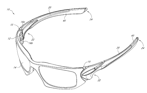
[0021] As shown in FIG. 1, eyewear 10 adapted to position a lens in a
predetermined orientation relative to the eyes can include a frame 12, lens 14
and
earstems 20. The earstems 20 can be pivotally affixed or joined to the frame
12 at
respective joints 15. The joints 15 can enable the earstems 20 to be
selectively pivoted
between a stowed position and a deployed position. As illustrated in FIG. 1,
the earstems
20 are positioned in the deployed position, ready for use. Although the
earstems 20 are
-3-
CA 02786117 2012-06-29
WO 2011/085254
PCT/US2011/020586
shown in FIG. 1 as pivotally affixed to the frame 12, the earstems 20 may be
permanently
attached in a predetermined orientation or selectively engageable with the
frame 12
without circumventing the scope of the present invention. Alternatively, the
frame 12 may
be eliminated entirely by securing the earstems 20 with or without earstem
hinges directly
to the lens 14 by thermoplastic bonding, adhesives screws or other fastening
means which
are suitable for the material of the lens and earstems.
[0022] In some embodiments, the frame 12 and earstems 20 can be
fabricated
using metals, polymers, or other relatively stiff materials that can have
desirable lens
securing and stabilizing properties while nevertheless enabling the eyewear to
provide
desirable flexural properties in the earstems 20 thereof. For example, in some
embodiments, titanium, carbon fiber, plastic, aluminum, and other such
materials can be
used in the frames 12 and/or earstems 20 to provide superior mechanical
properties while
reducing the weight of the eyeglass. Any suitable metals, plastics or other
rigid materials
can be used to form the eyeglass to provide exceptional rigidity, durability,
and wear
resistance. Nevertheless, various features and aspects disclosed herein can be
used in
eyeglasses fabricated from any material, e.g., plastic, acetate, composite,
metal, etc., or
any combination thereof. The lens 14 may take any of a number of
configurations and
can be formed of sheet plastic, molded plastic, glass, etc., as determined by
the
application of the lens.
[0023] Each earstem 20 can include an anterior end 22 and a posterior
end 24,
wherein the anterior end 22 is affixed either permanently or detachably to the
frame 12
and the posterior end 24 is generally free. The earstems 20 can be made of any
suitable
material, such as plastic, acetate, composite, metal, etc. A permanent
attachment of the
earstems to the frame 12 may be accomplished, for example, through molding or
thermoplastic bonding. A detachable engagement of the earstems 20 and the
frame 12
can be provided by various methods, such as with the use of a snap fit or
fasteners
including screws or pins.
[0024] As shown in FIG. 1, in some embodiments, the eyewear includes a
detachable hinge connection. The frame 12 or lens 14 can include hinge
apertures (not
illustrated) disposed on the inner surfaces of the upper and lower frame
flanges 16a, 16b,
such that the apertures are open toward each other. As illustrated in FIG. 3,
the earstems
20 can include a pair of parallel earstem flanges 18a, 18b with protrusions
(not illustrated)
on the outer surfaces that extend in opposite directions. The earstem flanges
18a, 18b can
-4-
CA 02786117 2012-06-29
WO 2011/085254
PCT/US2011/020586
be inserted by deformation of the frame flanges 16a, 16b and/or the earstem
flanges 18a,
18b, wherein the protrusions snap into the apertures, thereby providing a
readily
detachable hinge. In other embodiments, the apertures can be disposed on the
outer
surfaces of the earstem flanges 18a, 18b and the protrusions can be disposed
on the inner
surfaces of the frame flanges 16a, 16b.
[0025] In some embodiments, hinge apertures can extend through the
frame
flanges 16a, 16b and earstem flanges 18a, 18b. The apertures in the earstem
flanges 18a,
18b can be aligned with the apertures of the frame flanges 16a, 16b and a pin
can be
inserted so as to permit rotation of the frame 12 or lens 14 relative to the
earstems 20,
thereby providing a hingeable connection. In other embodiments, other
hingeable
connections known in the art are contemplated, such as hingeable connections
that are
readily detachable.
[0026] In some embodiments, the eyewear can include a curved portion
at or
near the posterior end 24 of the earstem to provide loops or bends which can
be
positioned behind the ears when the eyewear is worn. However, the earstem can
impinge
upon the head in undesired locations when employed on heads of different
sizes. Hence,
in some embodiments as illustrated in FIGS. 1-3, the eyewear can include a
generally
straight earstem which can provide more universally fitting eyewear and can
eliminate the
traditional ear hook which can cause discomfort or distraction for many
wearers.
[0027] As illustrated in FIGS. 2, 3 and 5, an earstem member, such as
a
traction member 40, can cover a lower portion of the earstem 20 so that at
least a portion
of the traction member 40 contacts or abuts a portion of the wearer's head,
such as an
upper portion of a wearer's ear, when the eyewear is used. In the illustrated
embodiment,
the traction member 40 extends over the lower portion of nearly the entire
length of the
earstem 20 to comfortably accommodate various head sizes of wearers in a
generally
stable manner and to provide a relatively long region for comfortably and more
securely
gripping the eyewear when holding it in the hands or when positioning it on a
wearer's
face. In some embodiments, the length of the traction member 40 can range from
approximately half to approximately the entire length of the earstem. In some
embodiments, as illustrated, at least about three-quarters of the lower edge
of the earstem
is generally covered by the traction member 40.
[0028] As illustrated in FIGS. 2, 3, 4 and 7, in some embodiments the
traction
member 40 can have a portion that generally or entirely extends around, or
that generally
-5-
CA 02786117 2014-10-23
or entirely surrounds, the earstem 20. In other embodiments, as illustrated in
FIG. 12, the
traction member 40 may extend along only one side (e.g., the lower portion) of
the
earstem 20 without a portion that extends along the other side (e.g., the
upper portion) of
the earstem 20. The traction member 40 can extend partially around the
periphery of the
earstem along a portion of its axial length, such as along a majority, or
approximately all,
of its axial length. In some embodiments, such configurations can provide a
generally
rigid surface along the upper edge of the earstem 20 and a generally resilient
or generally
soft-contact surface along the lower edge of the earstem 20.
[0029] With reference to FIG. 8, a recessed seat 30 can be disposed
intermediate of the anterior and posterior ends 22, 24 of the earstem 20. In
some
embodiments, the length and shape of the recessed seat 30 can generally
correspond to the
length and shape of the traction member 40 so that the traction member 40 can
fit closely
within and be securely bounded by the recessed seat 30. In some embodiments,
as
illustrated, the outer surface boundaries between the outer surfaces or edges
of the earstem
20 and the traction member 40 are generally smooth and continuous, without
substantial
gaps or substantial changes in shape or contour, along approximately all or a
portion of
the length of the earstem 20, so that the traction member 40 appears generally
to be an
integral or complementary part of the earstem 20 and so that debris does not
accumulate
along the boundaries. In some embodiments, the traction member 40 can be
attached to
or extend across approximately all or a portion of the earstem 20 without any
recessed
seat 30.
[0030] In the illustrated embodiment, the recessed seat 30 extends
over the lower
portion of a majority of the length of the earstem 20. The recessed seat 30
can include a first
portion that has a reduced outer surface cross-section around the entire (or
nearly the entire)
perimeter of the earstem 20, as illustrated in FIG. 10, and the recessed seat
30 can include a
second portion that has a reduced outer surface cross-section around less than
the entire
perimeter of the earstem 20. The second portion of the recessed seat 30 can
include an axially
extending shoulder, which in some embodiments can extend generally diagonally
across at least
a portion of the length (or generally the entire length) of the earstem 20. In
the illustrated
example, the axially extending shoulder extends from an upper portion on the
sidewall of the
earstem 20 that is closer to the posterior end 24 to a lower portion on the
sidewall of the earstem
20 that is closer to the anterior end 22. In some embodiments, as illustrated,
the portion of
-6-
CA 02786117 2014-10-23
the earstem 20 across which the axially shoulder extends is substantially
axially longer
than the portion of the earstem 20 where the recessed seat extends generally
completely
around the circumference of the earstem 20. The axially extending shoulder can
have a
generally curvilinear shape as illustrated. In some embodiments, the first
portion is
located in the posterior region of the earstem 20 and the second portion is
located in the
anterior region of the earstem 20. The first portion can be substantially
shorter than the
second portion. In some embodiments, all or nearly all of the recessed seat 30
is
structured as in the first portion, and in other embodiments, all or nearly
all of the
recessed seat 30 is structured as in the second portion 39. In some
embodiments, there
can be multiple recessed seats 30 and traction members 40 with axial spaces
between
them.
[0031] The term "recessed seat" is intended to have its ordinary
meaning. In
the illustrated embodiment (but not in all embodiments), the recessed seat 30
can be
defined by a posterior shoulder 34, an intermediate shoulder 32, and an
anterior shoulder
33. The intermediate shoulder 32 is disposed between the posterior shoulder 34
and the
anterior shoulder 33. The cross-sectional dimension of the recessed seat 30
between the
anterior and posterior shoulders 32, 34 can be smaller than the cross-
sectional dimension
of the adjacent portions of the earstem 20, as illustrated in FIGS. 8 and 11,
for example.
[0032] In some embodiments, such as some in which the traction member
40
extends along only the lower or upper side of the earstem 20 or around less
than the entire
perimeter of the earstem 20, the recessed seat 30 can be defined by a
posterior shoulder 36
and an anterior shoulder 38, as illustrated in FIG. 12, or by a single
shoulder 36, 38 in
suitable configurations. The cross-sectional dimension of the recessed seat 30
below the
shoulders 36, 38 can be smaller than the cross-sectional dimension of the
earstem 20
above the shoulders 36, 38.
100331 In some embodiments, such as some in which the recessed seat 30
includes a single shoulder (such as the posterior shoulder 34), the cross-
sectional area of
the seat can taper from being substantially flush with a portion of the
earstem 20 to a
reduced cross-sectional area at the shoulder. The single shoulder can thereby
prevent
unintentional axial displacement of the traction member 40 in one direction.
Axial displacement of the traction member in the other direction can be
inhibited by the
expanding cross-sectional area of the seat in a tapered embodiment, or by
other means
-7-
CA 02786117 2012-06-29
WO 2011/085254
PCT/US2011/020586
such as a friction fit. In some embodiments, axial displacement can be
inhibited by
additional retaining structures in the recessed seat 30, as described further
below.
[0034] Referring to FIG. 9, an example of an elongate, resilient
traction
member 40 is shown. The traction member 40 can have many different material
properties, such as flexibility, pliability, and enhanced gripping capability.
In some
embodiments, the traction member 40 can include a first portion 42 that is
formed with a
generally upwardly oriented opening or cavity 46 that is generally open along
the top
surface and is configured to interface with the lower surface of the earstem
20 in the
recessed seat 30. For some embodiments in which the first portion is
configured to be
positioned along the top edge of the earstem, the cavity can be open along the
bottom
surface. As illustrated, the first portion 42 can take the form of an elongate
body that is
split axially along the top wall so that it forms a generally trough-shaped,
partial tubular
body and not a completely closed tube.
[0035] In some embodiments, a second portion 44 can include a
generally
hollow, generally closed tubular body 44 configured to generally fit around
the recessed
seat 30. The tubular body 44 can have many different cross-sectional shapes,
such as
generally circular, generally square, generally triangular, generally
elliptical, etc.
The tubular body 40 can be completely closed and continuous around its
perimeter or it
can include openings or perforations. In some embodiments, the traction member
40 can
be stretchable or expandable to permit passage of a portion of the earstem
through a bore
therein, such as the posterior end 24 of the earstem 20, without exceeding the
elastic
limits of deformation of the traction member 40.
[0036] In the embodiment illustrated in FIG. 10, the traction member
40 has a
generally trapezoidal cross-sectional shape. In some embodiments, the cross-
sectional
shape of the traction member 40 is complimentary to the cross-sectional shape
of the
earstem 20 so that the assembled earstem 20 and traction member 40 form an
integrated
and continuous shape, such as for example the polygonal shape illustrated in
FIG. 11.
[0037] In some embodiments, the traction member 40 has a similar or
corresponding thickness to the depth of the recessed seat 30 so that the outer
surface 49 of
the traction member 40 is generally aligned with the outer surface of the
earstem 20 when
the two components are assembled, as illustrated in FIG. 11. When the traction
member
40 is generally flush with the adjacent earstem 20, it can provide an improved
aesthetic
appearance of the eyewear by helping to create a sleek, integrated appearance
of the
-8-
CA 02786117 2012-06-29
WO 2011/085254
PCT/US2011/020586
eyewear. In other embodiments, the traction member 40 can extend beyond the
periphery
of the earstem 20, or conversely the earstem 20 can extend beyond the
periphery of the
traction member 40.
[0038] In some embodiments, at least a portion of the earstem 20 and
at least a
portion of the traction member 40 can include interfacing structures to
increase or
complicate the forces required to separate them. In this way, the traction
member 40 is
less likely to inadvertently become detached from the earstem 20 during use.
For
example, in some embodiments, the recessed seat 30 can have a retention
structure for
securing the traction member 40 to the earstem 20. As illustrated in FIG. 8,
the recessed
seat 30 can include a plurality of slots 50 on the lower edge of the recessed
seat 30 for
accepting a plurality of complimentary ridges 52 of the traction member 40. Of
course,
the locations and/or orientations of the respective slots 50 and ridges 52 can
be reversed
or otherwise modified, and also one or more of each type of retention
structure can be
included on both the earstem 20 and traction member 40. The ridges 52 on the
traction
member 40 can be inserted into the slots 50 of the recessed seat 30 such that
the friction
between the ridges 52 and the slots 50 and/or the tension in the traction
member 40 can
help secure the traction member 40 to the earstem 20. In the illustrated
embodiment, the
recessed seat 30 has five slots 50 disposed on the first portion 42. In other
embodiments,
there can be less or more slots 50. In some embodiments, the slots 50 can be
disposed on
the second portion 44 in addition to or instead of the first portion 42. In
addition to or
instead of using integrated interfacing and retaining structures, the traction
member 40
and the earstem 20 can be attached to each other using adhesive,
thermobonding,
overmolding, sonic welding, solvent bonding, or any other suitable methods or
materials.
[0039] With continued reference to FIG. 8, the retention structure can
include
one or more closely fitting engaging structures, for example the slots 50 can
include an
enlarged portion 54 at the apical end of the slots 50. The traction member 40
can include
an enlarged or bulbous portion 56 at the top end of the ridges 52. As the
traction member
40 is coupled to the earstem 20, the bulbous portion 56 can deform as it is
inserted into
the enlarged portion 54 and then the bulbous portion 56 can at least partially
rebound to
its original size and shape. The bulbous portion 56 can provide an
interference fit with
the enlarged portion 54 to help secure the traction member 40 to the earstem
20 and to
help prevent the traction member 40 from unintentionally separating from the
recessed
seat 30. In the illustrated embodiments, the bulbous portion 56 and/or
enlarged portion 54
-9-
CA 02786117 2012-06-29
WO 2011/085254
PCT/US2011/020586
have a generally circular cross-sectional shape. However, in other
embodiments, the
shape of the bulbous portion 56 and/or enlarged portion 54 can be any other
shape, such
as oval or rectangular.
[0040] To help prevent the traction member 40 from displacing axially
(such
as in the posterior direction), the recessed seat 30 can include a first
retainer, such as hook
58, oriented toward the opposing end (such as the anterior end) of the
recessed seat 30, as
illustrated in FIG. 8. The hook 58 can be inserted into or connected with a
second
retainer, such as a pocket 60 as illustrated in FIG. 9, on the traction member
40 to
releasably hold an end portion of the traction member 40 to the earstem 20. In
some
embodiments, the traction member 40 can be made of an elastomeric material
that can be
stretched so that the pocket 60 can be fitted over the hook 58. The
elastomeric material
can generally rebound to its original size and provide a compression or
tensile force that
releasably holds the pocket 60 against the hook 58. In some embodiments, the
recessed
seat 30 can include a second hook oriented toward the opposite end of the
first hook 58
(such as the posterior end) of the earstem 20. The second hook can be
particularly
advantageous to provide a securing means in embodiments (see, for example,
FIG. 12)
that do not include a second portion 44 that wraps around the recessed seat
30. In
embodiments wherein the traction member 40 is disposed only on the lower
portion of the
earstem 20, a second hook oriented toward the posterior end of the earstem 20
can secure
the posterior end of the traction member 40. The traction member 40 can
include a
second pocket that can be attached over the second hook. In addition to, or
instead of,
using interfacing and retaining structures, the traction member 40 and the
earstem 20 can
be attached to each other using other attachment means such as adhesive,
thermobonding,
overmolding, sonic welding, solvent bonding, or any other suitable methods and
materials.
[0041] In some embodiments, the length of the traction member 40 in
its
resting state (before attachment to the earstem 20) can be slightly shorter
than the length
of the recessed seat 30 (or the length between respective retaining
structures) so that the
traction member 40 is axially stretched across at least a portion of the
earstem 20 when it
is attached thereto. For example, the anterior end of the traction member 40
with a first
pocket can be stretched over the first hook to create a pulling or tensile
force between the
anterior and posterior ends of the traction member 40, which can releasably
hold the
traction member 40 to the recessed seat 30. In some embodiments, the
corresponding
-10-
CA 02786117 2012-06-29
WO 2011/085254
PCT/US2011/020586
opposing force is provided by a second retainer or by a shoulder, such as
intermediate
shoulder 32. The tension created in the traction member 40 by this stretching
method of
attachment can help prevent unintentional detachment until a force is applied
in a
particular direction to remove it.
[0042] In some embodiments, the traction member 40 can be coupled to
an
underlying carrier (not shown) that can act as an adapter for attachment to
the earstem 20.
The carrier can include mounting features similar to or the same as those
described above
for the earstem 20 and traction member 40. In some embodiments, the carrier
can be
generally trough-shaped so as to grip at least a portion of the earstem 20
along opposing
sidewalls. The opposing sidewalls of the carrier can be manufactured to be
biased to a
particular shape and orientation that produces a restoring force to help
secure the carrier to
the earstem 20. For example, when attached to an earstem 20, the sidewalls of
the carrier
may be bent outwardly to receive a portion of the earstem 20, which can
produce an
opposing lateral force against the earstem 20, thereby increasing the force
required to
remove the carrier. In some embodiments, the carrier can be made of a more
rigid
material than the traction member 40, such as a harder plastic or composite.
The traction
member 40 can be attached to the carrier by any means known in the art, such
as through
adhesives or over-molding. In turn, the carrier can be attached to the earstem
20 through
any means described herein or known in the art. In some embodiments, the
carrier can be
releasably attached to the earstem 20 so that the traction member 40 can be
interchanged
easily. In some embodiments, the carrier can provide rigidity to the traction
member 40
while still preserving the cushion and comfort provided by the elastomeric
material of the
traction member 40.
[0043] Other attachment means may be employed to couple the traction
member 40 to the earstem 20, such as providing a bias in the opening or cavity
46 so that
the open sides of the traction member 40 are biased towards one another, which
in some
embodiments can tend to form an enclosed cavity. The bias can be sufficient so
that the
opposing sides of the traction member 40 cooperatively engage the periphery of
the
recessed seat 30 and the compression force from the biased sides is sufficient
to secure the
traction member 40 to the recessed seat 30.
[0044] In some embodiments, the attachment means can include one or
more
complimentary channels and grooves formed respectively in either or both of
the earstem
20 or the traction member 40. In some embodiments, the recessed seat can
include a
-11-
CA 02786117 2012-06-29
WO 2011/085254
PCT/US2011/020586
flange around which the traction member can be wrapped to secure to the
recessed seat.
In many embodiments of the attachment means, the traction member is releasably
attached to the recessed seat to facilitate easy removal and exchange of the
traction
member after excessive wear or damage, or when a user desires a different look
or fit for
the eyewear.
[0045] The
traction member 40 is preferably comprised of a material having
sufficient elasticity that the inner surface 48 of the traction member 40 can
be configured
to snugly contact the surface of the recessed seat 30 with a cross-sectional
area greater
than that of the inner surface 48 in the unexpanded state. The inner surface
48 can
conform snugly to the surface of a recessed seat 30 having various cross-
sectional shapes,
such as a circular or rectangular cross-section.
[0046] In
some embodiments, the traction member 40 may be formed by a
molding or extruding processes. The outer surface 49 of the traction member 40
can be
configured to enhance the coefficient of static friction between the eyewear
and the head.
The outer surface 49 may be formed to exhibit a variety of static friction
coefficient
enhancing configurations, such as ridges, bumps, or textured surface (not
shown). In
some embodiments, the outer surface 49 produced by extrusion can exhibit
axially
oriented patterns, while molded outer surfaces may exhibit axially and/or
radially oriented
patterns.
[0047] As
discussed infra, the traction member 40 can be formed of an
elastomeric material exhibiting sufficient flexibility or elasticity to allow
the traction
member 40 to expand while being slipped over the earstem posterior end 24 and
to
contract back against the recessed seat 30 after passing over the posterior
end 24.
[0048] In
some embodiments, the traction member 40 is formed of a relatively
soft elastomeric material having a coefficient of sliding friction that
increases when the
material is wetted. Such a material, sometimes referred to as hydrophilic,
tends to enhance
retention of the traction member 40 in position on the wearer's head as the
wearer
perspires or encounters moisture, as during skiing.
[0049] In
some embodiments, the traction member 40 can comprise a resilient
sponge-like elastomeric material, having a relatively high porosity. In
some
embodiments, the traction member 40 can comprise a substantially solid, e.g.,
fine or no
porosity, yet flexible material, such as synthetic or natural rubber or rubber-
like materials.
An example of a material for a traction member 40 is Kraton G polymer. The
traction
-12-
CA 02786117 2012-06-29
WO 2011/085254
PCT/US2011/020586
member 40 may be made of materials having different densities, thereby
providing
traction members 40 having different weights, which may be employed to
counterbalance
lenses of differing weights, so as to balance the weight of the eyewear 10
more evenly
about the head.
[0050] Although the traction member 40 is illustrated as extending
approximately two-thirds to approximately three-fourths the overall length of
the earstem,
the traction members 40 can extend anywhere from substantially the entire
length of the
earstem 20 to only a relatively small portion thereof. A plurality of traction
members 40
may be axially aligned within the recessed seat 30. The traction members 40
may be
selected so that a combined length of the members 40 substantially equals the
distance
between the anterior and posterior shoulders 32, 34 or alternatively, the
combined axial
length of the traction members 40 may be such that an axial space separates
adjacent
traction members 40 within the recessed seat 30.
[0051] On the illustrated embodiment, in assembling the traction
member 40
to the earstem 20, the posterior end 24 of the earstem 20 can be passed
through the hollow
tubular body within the second portion 44 of the traction member 40. In some
embodiments, the earstem 20 may be detached from the frame 12 or lens 14 and
the
anterior end 22 may be passed through the tubular passageway of the traction
member 40.
The traction member 40 is then moved along the earstem 20 until the inner
surface 48
engages the seat 30. Next, the first portion 42 can be coupled to the recessed
seat through
any of the means discussed above.
[0052] In some embodiments where the recessed seat 30 has a length
substantially equal to the length of the traction member 40, as the traction
member 40 is
received within the recessed seat 30, further unintended motion along the
earstem 20 is
prevented by engagement of the anterior and posterior shoulders 32, 34 with
the traction
member 40.
[0053] The seat 30 may have a sufficient axial length so as to retain
a plurality
of traction members 40 between the anterior and posterior shoulders 32, 34.
The use of
multiple traction members 40 allows for accommodating fashion considerations
as well as
high retaining forces for active uses, such as volleyball or basketball. Upon
engagement of
the traction member 40 within the seat 30, the outer surface 49 of the
traction member 40
may be disposed outside of the periphery of the earstem 20 or may be
substantially flush
with the periphery 38 of the adjacent earstem 20, as shown in FIG. 11.
Traction members
-13-
CA 02786117 2012-06-29
WO 2011/085254
PCT/US2011/020586
can be provided having a variety of wall thicknesses. Thus, the wearer can
select a flush
fitting traction member as illustrated in FIG. 11 or a radially enlarged
traction member,
depending upon that wearer's perception of the need for enhanced traction or
sleek
appearance.
[0054] An advantage of certain embodiments includes the ability to
releasably
attach the traction member 40 to the earstem 20 so that the traction member 40
can be
exchanged or replaced. For example, when the traction member 40 becomes worn,
it can
be replaced with another traction member. In some instances, the traction
member 40 can
be exchanged with a traction member with a different design, style or material
characteristics to suit a particular activity or situation. For active
occasions, a secure
fitting and cushioned traction member can be attached to the earstem 20. On
the other
hand, for leisurely occasions a sleeker, more colorful and fashionable
traction member can
be attached. In some instances, the traction member can be custom molded to
the shape
and size of the wearer and then attached to a standard earstem for a cost
effective,
customized fit.
[0055] In some embodiments in which the traction members do not
surround
the entire earstem, there is more freedom in the earstem designs to
incorporate better
flexural control and flexural stress distribution while not adding to the
overall earstem
thickness. The freedom in the earstem designs can be enhanced since the size
of the
earstem does not need to be diminished around its entire periphery to
accommodate a full
circumferential traction member.
[0056] Although these inventions have been disclosed in the context of
certain
preferred embodiments and examples, it will be understood by those skilled in
the art that
the present inventions extend beyond the specifically disclosed embodiments to
other
alternative embodiments and/or uses of the inventions and obvious
modifications and
equivalents thereof. In addition, while several variations of the inventions
have been
shown and described in detail, other modifications, which are within the scope
of these
inventions, will be readily apparent to those of skill in the art based upon
this disclosure.
It is also contemplated that various combination or sub-combinations of the
specific
features and aspects of the embodiments may be made and still fall within the
scope of the
inventions. It should be understood that various features and aspects of the
disclosed
embodiments can be combined with or substituted for one another in order to
form
varying modes of the disclosed inventions. Thus, it is intended that the scope
of at least
-14-
CA 02786117 2012-06-29
WO 2011/085254
PCT/US2011/020586
some of the present inventions herein disclosed should not be limited by the
particular
disclosed embodiments described above.
-15-