Note: Descriptions are shown in the official language in which they were submitted.
CA 02786510 2012-07-05
WO 2011/085146 PCT/US2011/020442
236548
COMPACT LIGHT-MIXING LED LIGHT ENGINE AND WHITE LED LAMP WITH
NARROW BEAM AND HIGH CRI USING SAME
BACKGROUND
[0001] The following relates to the illumination arts, lighting arts, solid
state lighting arts, and
related arts.
[0002] Incandescent and halogen lamps are conventionally used as both omni-
directional and
directional light sources. A directional lamp is defined by the US Department
of Energy in its
Energy Star Eligibility Criteria for Integral LED Lamps, draft 3, as a lamp
having at least 80% of
its light output within a cone angle of 120 degrees (full-width at half-
maximum of intensity,
FWHM). They may have either broad beam patterns (flood lamps) or narrow beam
patterns (e.g.,
spot lamps), for example having a beam intensity distribution characterized by
a FWHM < 200
,
with some lamp standards specified for angles as small as 6-10 FWHM.
Incandescent and
halogen lamps combine these desirable beam characteristics with high color
rendering index
(CRI) to provide good light sources for the display of retail merchandise,
residential and
hospitality lighting, art work, etc. For commercial applications in North
America, these lamps
are designed to fit into a standard MR-x, PAR-x, or R-x lamp fixture, where
"x" denotes the
outer diameter of the fixture, in eighths of an inch (e.g. PAR38 has 4.75"
lamp diameter ¨ 120
mm). There is equivalent labeling nomenclature in other markets. These lamps
have fast
response time, output high light intensity, and have good CRI characteristics,
especially for
saturated red (e.g., the R9 CRI parameter), but suffer from poor efficacy and
relatively short
lamp life. For still higher intensities, high intensity discharge (HID) lamps
are used, at the cost of
reduced response time due to the need to heat the liquid and solid dose during
the warm-up phase
after turning on the lamp, and typically also reduced color quality, higher
cost, and moderate
lamp life ¨ 10k ¨ 20k hours.
[0003] Although these existing MR/PAR/R spotlight technologies provide
generally acceptable
performance, further enhancement in performance and/or color quality, and/or
reduction in
manufacturing cost, and/or increased wall plug energy efficiency, and/or
increased lamp life and
reliability would be desirable. Toward this end, efforts have been directed
toward developing
1
CA 02786510 2012-07-05
WO 2011/085146 PCT/US2011/020442
236548
solid-state lighting technologies such as light emitting diode (LED) device
technologies. The
desirable characteristics of incandescent and halogen spot lamps include:
color quality; color
uniformity; beam control; and low acquisition cost. The undesirable
characteristics include: poor
efficacy; short life; excessive heat generation; and high life-cycle operating
cost.
[0004] For MR/PAR/R spot light applications, LED device technologies have been
less than
satisfactory in replacing incandescent and halogen lamps. It has been
difficult using LED device
technologies to simultaneously achieve a combination of both good color and
good beam control
for spot lamps. LED-based narrow-beam spot lighting has been achieved using
white LEDs as
point light sources coupled with suitable lenses or other collimating optics.
This type of LED
device can be made with narrow FWHM in a lamp envelope comporting with
MR/PAR/R fixture
specifications. However, these lamps have CRI characteristics corresponding to
that of the white
LEDs, which is unsatisfactory in some applications. For example, such LED
devices typically
produce R9 values of less than 30, and CRI ¨ 80-85 (where a value of 100 is
ideal) which is
unacceptable for spot light applications such as product displays, theater and
museum lighting,
restaurant and residential lighting, and so forth.
[0005] On the other hand, LED based lighting applications other than spot
lighting have
successfully achieved high CRI by combining white LED devices with red LED
devices that
compensate for the red deficient spectrum of typical white LED devices. See,
e.g., Van De Ven
et al., U.S. Pat. No. 7,213,940. To ensure mixing of light from the white and
red LED devices, a
large area diffuser is employed that encompasses the array of red and white
LED devices. Lamps
based on this technology have provided good CRI characteristics, but have not
produced spot
lighting due to large beam FWHM values, typically of order 1000 or higher.
[0006] A combination of good color quality, good beam control and uniform
illuminance and
color in the beam has also been achieved by using a deep (or long) color-
mixing cavity that
provides multiple reflections of the light, or a long distance between the LED
array and the
diffuser plate, albeit at the cost of increased light losses due to cavity
absorption, and increased
lamp size.
2
CA 02786510 2012-07-05
WO 2011/085146 PCT/US2011/020442
236548
[0007] It has also been proposed to combine these technologies. For example,
Harbers et al.,
U.S. Publ. Appl. No. 2009/0103296 Al discloses combining a color-mixing cavity
consisting of
an array of LED devices mounted on an extended planar substrate that is
mounted at the small
aperture end of a compound parabolic concentrator. Such designs arc calculated
to theoretically
provide arbitrarily small beam FWHM by using a color-mixing cavity of
sufficiently small
aperture. For example, in the case of a PAR 38 lamp having a lamp diameter of
120 mm, it is
theoretically predicted that a color-mixing cavity of 32 mm diameter coupled
with a compound
parabolic concentrator could provide a beam FWHM of 30 .
[0008] However, as noted in Harbers et al. the compound parabolic concentrator
design tends to
be tall. This could be problematic for an MR or PAR lamp which has a specified
maximum
length imposed by the MR/PAR/R regulatory standard to ensure compatibility
with existing
MR/PAR/R lamp sockets. Harbers et al. also proposed using a truncated compound
parabolic
concentrator having a truncated length in place of the simulated compound
parabolic reflector.
However, Harbers et al. indicate that truncation is expected to increase the
beam angle. Another
approach proposed in Harbers et al. is to design the color-mixing cavity to be
partially forward-
collimating through the use of a pyramidal or dome-shaped central reflector.
However, this
approach can compromise color-mixing and hence the CRI characteristics, and
also may
adversely affect optical coupling with the compound parabolic concentrator,
since the number of
times that each light ray bounces on the side wall and becomes mixed in color
and in spatial
distribution is greatly reduced.
BRIEF SUMMARY
[0009] In some embodiments disclosed herein as illustrative examples, a
directional lamp
comprises a light source, a beam forming optical system configured to form
light from the light
source into a light beam, and a light mixing diffuser arranged to diffuse the
light beam. The light
source, beam forming optical system, and light mixing diffuser are secured
together as a unitary
lamp. The beam forming optical system includes: a collecting reflector having
an entrance
aperture receiving light from the light source and an exit aperture that is
larger than the entrance
aperture, and a lens disposed at the exit aperture of the collecting
reflector, the light source being
3
CA 02786510 2012-07-05
WO 2011/085146 PCT/US2011/020442
236548
positioned along an optical axis of the beam forming optical system at a
distance from the lens
that is within plus or minus ten percent of a focal length of the lens.
[0010] In some embodiments disclosed herein as illustrative examples, a
directional lamp
comprises: a light source; a lens arranged to form light emitted by the light
source into a light
beam directed along an optical axis, the light source being spaced apart from
the lens along the
optical axis by a distance that is within plus or minus ten percent of a focal
length of the lens;
and a reflector arranged to reflect light from the light source that misses
the lens into the lens to
contribute to the light beam; wherein the light source, lens, and reflector
are secured together as a
unitary lamp.
[0011] In some embodiments disclosed herein as illustrative examples, a
lighting apparatus
comprises: a light mixing cavity including a planar light source comprising
one or more one light
emitting diode (LED) devices disposed on a planar reflective surface, a planar
light transmissive
and light scattering diffuser of maximum lateral dimension L arranged parallel
with the planar
light source and spaced apart from the planar light source by a spacing S
wherein the ratio S/L is
less than three, and reflective sidewalls connecting a perimeter of the planar
light source and a
perimeter of the diffuser.
BRIEF DESCRIPTION OF THE DRAWINGS
[0012] The invention may take form in various components and arrangements of
components,
and in various process operations and arrangements of process operations. The
drawings are
only for purposes of illustrating preferred embodiments and are not to be
construed as limiting
the invention.
[0013] FIGURES 1-15 diagrammatically shows various LED arrays including one or
more
LEDs on a generally circular circuit board, arranged either symmetrically or
asymmetrically on
the board.
4
CA 02786510 2012-07-05
WO 2011/085146 PCT/US2011/020442
236548
[0014] FIGURES 16-18 diagrammatically shows various LED arrays including one
or more
LEDs on a generally polygonal circuit board, arranged either symmetrically or
asymmetrically
on the board.
[0015] FIGURES 19-22 diagrammatically shows various light engine embodiments
each
including an array of one or more LEDs on a circuit board, an optically
reflective side-wall, and
an optically diffusing element.
[0016] FIGURE 23 diagrammatically shows a lamp containing a light engine and
beam-
forming optics including a conical reflector and lens.
[0017] FIGURE 24A diagrammatically shows a lamp containing a light engine,
beam forming
optics including a conical reflector and lens, and an optically diffusing
element located adjacent
an optically reflective side wall.
[0018] FIGURE 24B diagrammatically shows a lamp containing a light engine,
beam forming
optics including a conical reflector and lens, an optically diffusing element
located adjacent an
optically reflective side wall, and an optically diffusing element located
near the output aperture
of the MR/PAR/R lamp.
[0019] FIGURE 24C diagrammatically shows a lamp containing a light engine,
beam forming
optics including a conical reflector and lens, and an optically diffusing
element located near the
output aperture of the MR/PAR/R lamp.
[0020] FIGURES 25, 26, and 27 illustrate one approach for constructing the
conical reflector of
FIGURE 23.
[0021] FIGURE 28 diagrammatically shows beam angle (FWHM) versus diameter of
the disc
light source, for a range of lamp exit apertures 50, 63, 95, and 120 mm
corresponding to the
maximum possible exit aperture for MR16, PAR20, PAR30, and PAR38 lamps having
no heat
fins, according to the approximate formula: 0.
assuming that the intensity distribution of
D.
the LED array has a FWHM 120 degrees (i.e. nearly Lambertian).
CA 02786510 2012-07-05
WO 2011/085146 PCT/US2011/020442
236548
[0022] FIGURE 29 diagrammatically shows beam angle (FWHM) vs. diameter of the
disc light
source, for a range of lamp exit apertures 38, 47, 71, and 90 mm corresponding
to a typical exit
aperture for MR16, PAR20, PAR30, and PAR38 lamps having typical heat fins
surrounding the
exit aperture, according to the approximate formula: G.
assuming that the intensity
D.
distribution of the LED array has a FWHM 120 degrees (i.e. nearly Lambertian),
and assuming
that the exit aperture diameter is 75% of the maximum possible exit aperture
diameter.
[0023] FIGURE 30 diagrammatically shows the typical lamp beam angle as a
function of the
ratio of the light source aperture to the lamp exit aperture, assuming that
the light source has
nearly a lambertian intensity distribution, characterized by a FWHM of
approximately 120
degrees.
[0024] FIGURES 31A and 31B show two embodiments of lenses having a light
diffuser formed
into a principal surface of the lens.
DETAILED DESCRIPTION OF PREFERRED EMBODIMENTS
[0025] Disclosed herein is an approach for designing LED based spot lights,
which provides a
flexible design paradigm capable of satisfying the myriad design parameters of
a family of
MR/PAR/R lamps or compact LED modules that enable improved optical and thermal
access to
the light engine. The spot lights disclosed herein employ a low profile LED-
based light source
optically coupled with beam forming optics. The low profile LED-based light
source typically
includes one or more LED devices disposed on a circuit board or other support,
optionally
disposed inside a low-profile light-mixing cavity. In some embodiments, a
light diffuser is
disposed at the exit aperture of the light-mixing cavity. In some embodiments
the light diffuser is
disposed in close proximity to the LED array wherein the low profile LED-based
light source is
sometimes referred to herein as a pillbox, wherein the circuit board
supporting the LED devices
is a "bottom" of the pillbox, the light diffuser at the exit aperture is the
"top" of the pillbox, and
"sides" of the pillbox extend from the periphery of the circuit board to the
periphery of the
diffuser. To form a light-mixing cavity, the circuit board and sides of the
pillbox arc preferably
light-reflective. Because the pillbox has a low profile, it is approximately
disc-shaped, and hence
6
CA 02786510 2012-07-05
WO 2011/085146 PCT/US2011/020442
236548
the LED-based light sources employed herein are sometimes also referred to as
disc light
sources. In other embodiments the diffuser is located elsewhere in the beam
path. For example,
in some embodiments the diffuser is located outside the beam-forming optics so
as to operate on
the formed light beam. This arrangement, coupled with a diffuser designed to
operate on a light
beam of relatively narrow full-width at half-maximum (FWHM), is disclosed to
provide
substantial benefits.
[0026] A first aspect of this lamp design abandons the approach of modifying
an existing
optimal beam-forming optics configuration. Rather, the approach disclosed
herein is based on
first principles of optical design. For example, it is shown herein that an
illuminated disc light
source can be optimally controlled by beam-forming optics that satisfy a
combination of etendue
and skew invariants for the disc light source. One such design employs beam-
forming optics
including a lens (e.g., a Fresnel or convex lens) in which the disc light
source is placed at the lens
focus so that the disc light source is "imaged" at infinity, coupled with a
collecting reflector to
capture light rays that would otherwise miss the imaging lens. In some variant
embodiments, the
disc light source is placed in a slightly defocused position, for example
along the beam axis
within plus or minus 10% of the focal distance. The defocusing actually
produces less perfect
beam formation insofar as some light spills outside the beam FWHM ¨ however,
for some
practical designs such light spillage is aesthetically desirable. The
defocusing also produces
some light mixing which is advantageous when the light source includes
discrete light emitting
elements (e.g., LED devices) and/or when these discrete light emitting
elements are of different
colors or otherwise have different light output characteristics that are
advantageously blended.
Additionally or alternatively, a light-mixing diffuser may be added to achieve
a designed amount
of light spillage outside the FWHM and/or a designed amount of light mixing
within the beam.
[0027] The performance of the light beam can be quantified by several
characteristics that are
typically measured in the far field (typically considered to be at a distance
at least 5-10 times the
exit aperture size of the lamp, or typically about one-half meter or further
away from the lamp).
The following definitions are respective to a beam pattern that is peaked near
the center of the
beam, on the optical axis of the lamp, with generally reduced intensity moving
outward from the
optical axis to the edge of the beam and beyond. The first performance
characteristic is the
7
CA 02786510 2012-07-05
WO 2011/085146 PCT/US2011/020442
236548
maximum beam intensity that is referred to as maximum beam candlepower (MBCP),
or since
the MBCP is usually found at or near the optical axis, it may also be referred
to as center-beam
candlepower (CBCP). It measures the perceived brightness of the light at the
maximum, or at
the center, of the beam pattern. The second is the beam width represented by
the full width at
half maximum (FWHM), which is the angular width of the beam at an intensity
equal to one-half
of the maximum intensity in the beam (the MBCP). Related to FWHM is the beam
lumens,
defined as the integral of the lumens from the center of the beam, outward to
the intensity
contour having one-half of the maximum intensity, that is, the lumens
integrated out to the
FWHM of the beam. Further, if the integration of lumens continues outward in
the beam to the
intensity contour having 10% of the maximum intensity, the integrated lumens
may be referred
to as the field lumens of the lamp. Finally, if all of the lumens in the beam
pattern are integrated,
the result is referred to as the face lumens of the lamp, that is, all of the
light emanating from the
face of the beam-producing lamp. The face lumens are typically about the same
as the total
lumens, as measured in an integrating sphere, since typically little or no
light is emitted from the
lamp other than through the output aperture, or face, of the lamp.
[0028] Further, the uniformity of the intensity distribution and the color in
the beam can be
quantified. The following, a conventional cylindrical coordinate system is
used to describe the
MR/PAR/R lamp, including radial, r, polar angle, 0, and azimuthal angle, (1),
cylindrical
coordinate directions (see the cylindrical coordinate system as depicted in
FIGURES 24A, 24B,
and 24C, where the lamp includes a light engine LE and beam forming optics BF
including a
conical reflector and lens). Whereas it is generally preferred in most
illumination applications
that the intensity of the light in the beam pattern be peaked on axis and to
fall in intensity
monotonically away from the axis in the polar angle (0) direction, on the
other hand it is
generally preferred that there be no intensity variation in the orthogonal
(azimuthal angle, or
direction, and it is also generally preferred that the color of the light be
uniform throughout the
beam pattern. The human eye can typically detect intensity non-uniformities
exceeding about
20%. So, although the beam intensity decreases in the direction of the polar
angle, 0, from 100%
on axis (0 = 0) to 50% at FWHM, to 10% at the "edge" of the beam, to zero
intensity beyond the
edge of the beam, the intensity should preferably be contained within a range
<+/-20% around
8
CA 02786510 2012-07-05
WO 2011/085146 PCT/US2011/020442
236548
the azimuthal (1)) direction, at a given polar angle contour in the beam.
Additionally, the human
eye can typically recognize color differences exceeding about 0.005 ¨ 0.010 in
the 1931 ccx-ccy
or the 1976 u'-v' CIE color coordinates, or approximately 100 ¨ 200 K in CCT
for CCT in the
range of 2700 to 6000 K. So, the color uniformity throughout the beam pattern
should be
contained within a range of about Du'v' or Dxy of +/- 0.005 to 0.010, or
equivalently +/- 100 to
200 K, or less, from the average CCT of the beam.
[0029] In general, it is desirable to maximize the face lumens (total lumens)
of the light in the
beam, for a given electrical input to the lamp. The ratio of total face lumens
(integrating sphere
measurement) to electrical input power to the lamp is the efficacy, in lumens
per watt (LPW).
To maximize the efficacy of the lamp, it is known (see Non-Imaging Optics, by
Roland Winston,
et.al., Elsevier Academic Press, 2005, page 11) that the optical parameter
known as etendue (also
called the "extent" or the "acceptance" or the "Lagrange invariant" or the
"optical invariant")
should be matched between the light source (such as the filament in the case
of an incandescent
lamp, or the arc in the case of an arc lamp, or the LED device in the case of
an LED-based lamp,
or so forth) and the output aperture of the lamp (typically the lens or cover
glass attached to the
open face of a reflector, or the output face of a refractive, reflective or
diffractive beam forming
optic). The etendue (E) is defined approximately as the product of the surface
area (A) of the
aperture through which the light passes (normal to its direction of
propagation) times the solid
angle (f2) through which the light propagates, E = A. Etendue quantifies how
"spread out" the
light is in area and angle.
100301 Most conventional light sources can be crudely approximated by a right-
circular
cylinder having uniform luminance emitted from the surface of the cylinder
(for example, an
incandescent or halogen filament, or an HID or fluorescent lamp arc, or so
forth), and the
etendue of the source (the entrance aperture of the optical system) is
approximated by E = AsS2s,
where As is the surface area of the source cylinder (As = TERL, where R =
radius, L = length) and
f2 is typically a large fraction of 47 (12.56) steradians, typically ¨ 10 sr,
meaning that the light is
radiated nearly uniformly in all directions. A better approximation may be
that the light is
radiated with a Lambertian intensity distribution, or the emitted light may be
represented by an
actually measured spatial and angular 6-dim en si on al distribution function,
but a uniform
9
CA 02786510 2012-07-05
WO 2011/085146 PCT/US2011/020442
236548
distribution is illustrative. For example, a typical halogen coil having R=0.7
mm, L=5 mm, and
Q=10 sr has an etendue, Es ¨ 100 mm2-sr ¨ 1 cm2-sr. Similarly, an HID arc
having R=1 mm and
L=3.5 mm, also has Es ¨ 100 mm2-sr ¨ 1 cm2-sr, even though the shapes of the
coil and the arc
are different, and even though the HID arc may emit several times as many
lumens as the
halogen coil. The etendue is the "optical extent", or the size of the light
source in both the spatial
and the angular dimensions. The etendue should not be confused with the
"brightness" or
"luminance" of the light source ¨ luminance is a different quantitative
measure that accounts for
both the optical extent of the light source and the quantity of light
(lumens).
100311 In the case of the output face of a directional reflector lamp, the
exit aperture can be
approximated by a circular disc having uniform luminance through it, and the
etendue is
approximated by E = A0Q0, where Ao is the area of the disc (TER02, where Ro =
radius) and Q0 is
typically a small fraction of 27c steradians, characterized by the half-angle
of the beam of light,
00= FWHM/2 = HWHM (half width at half maximum), where Q0 = 2741¨ cos(00)) ,
e.g., for
00=90 , Q0=27c; for 00=60 , Q0=7E; for 00=30 , Q0=0.84; for 00=10 , Q0=0.10.
[0032] As light propagates through any given optical system, the etendue may
only increase or
remain constant, hence the term "optical invariant". In a loss-free and
scatter-free optical system,
the etendue will remain constant, but in any real optical system exhibiting
scattering or diffusion
of the light, the etendue typical grows larger as the light propagates through
the system. The
invariance of etendue is an optical analog to conservation of entropy (or
randomness) in a
thermodynamic system. The statement that E=AQ cannot be made smaller as light
propagates
through an optical system, means that in order to reduce the solid angle of
the light distribution,
the aperture through which the light passes must be increased. Accordingly,
the minimum beam
angle emitted from a directional lamp having an output aperture, Ao, is given
by
E0 = A0Q0 = AsQs = Es . Re-arranging, and substituting Q0 = 27z-(1¨ cos(00)) ,
yields
Es
cos(00) =1 . For 00<< 1 radian (that is, for 00<< 57 ), the cosine function
can be
27rAc,
approximated by cos(00) 1¨ G2, where 0 is expressed in radians. Combining the
above
expressions yields the following output beam half-angle 00:
CA 02786510 2012-07-05
WO 2011/085146 PCT/US2011/020442
236548
ilf/sAs = Es
22rAc, ;rA,, (1).
2
Doubling the half-angle 00 of Equation (1) yields the beam FWHM.
[0033] In the case of a PAR38 lamp having a circular output aperture, for
example, the area of
the maximum optical aperture at the face of the lamp is determined by the
diameter of the lamp
face = 4.75" = 12 cm, so the maximum allowable A0 is 114 cm2. For the examples
of etendue
given above for a halogen coil or an HID arc, then the minimum possible half-
angle, 0,, from a
PAR38 lamp driven by a light source having Es ¨ 1 cm2-sr is 00 ¨ 0.053 ¨ 3.0 ,
so the FWHM of
the beam would be 6.0 . In practice the narrowest beams available in PAR38
lamps typically
have FWHM 6-10 . If the available aperture (i.e. the lens or cover glass) at
the face of the
lamp is made smaller, then the beam angle will be larger in proportion to the
reduction in
diameter of the face aperture as per Equation (1).
[0034] In the case of a lamp with a circular face aperture of diameter Do and
a light source that
is a flat disc of diameter Dõ the output half-angle 0, of the beam is given by
Equation (1)
according to:
= Es __ ¨11f1sAs
_ _____________________
27r4 27-r40
D D 1127-1-(1¨ cos(0 ,) Ds __
s s s _______ = .v1¨ cos Os (2).
Do 27 Do 27r D,
Do
In order to provide a narrow spot beam in a lamp using LED devices, or
conventional
incandescent, halogen, or arc light sources, the light source should have a
small etendue. In
practice, an LED device comprising a single LED chip typically having a square
light-emitting
area with linear dimension ¨ 0.5-2.0 mm (A, ¨ 0.25 ¨ 4.0 mm2), an optional
encapsulation
providing a roughly Lambertian intensity distribution (Qs ¨ 7), and optional
wavelength-converting phosphor, typically have small etendues of about 1-10
mm2-sr, so that a
11
CA 02786510 2012-07-05
WO 2011/085146 PCT/US2011/020442
236548
narrow beam can be produced by providing a small, separate beam-forming optic
for each LED
device. If additional light is required, then additional LED devices, each
with a separate optic,
may be added. This is a known design approach for achieving narrow beam LED
lamps. A
problem with this approach is that the light from the individual LED devices
is not well-mixed.
In commercially available LED PAR/MR lamps, this design methodology typically
results in
relatively poor color quality (e.g., poor CRI) because the individual LEDs are
typically limited to
CRI ¨ 85 or less. Another problem with this design methodology is that the
beam-forming optic
typically has only 80-90% efficiency, so that along with other light-coupling
losses, the system
optical efficiency is typically ¨ 60-80%.
[0035] If it is desired to combine the light output of multiple LED devices
into a single light
beam in order to mix the colors of the individual LED devices into a
homogeneous light source
having uniform illuminance and color, in order to increase the CRI or some
other color quality of
the light beam, then a light-mixing LED light engine may be employed. A light-
mixing LED
light engine typically includes a plurality of LED devices disposed in a light-
mixing cavity. By
making the light-mixing cavity large and highly reflective, and spacing the
LED devices apart
within the light-mixing cavity, the light can be made to undergo multiple
reflections so as to mix
the light from the spaced apart LED devices. A commercially available example
of this design
methodology is the Cree LLF LR6 down-lighter LED lamp. It provides CRI ¨ 92
with FWHM
1100. In addition to the inability to create a spot beam, this design
methodology also suffers
from optical losses of at least ¨ 5% for each reflection or scattering of the
light within the light-
mixing chamber. For complete mixing of the color and luminosity of the light,
several reflections
are employed, so that the system optical efficiency is typically < 90%.
[0036] The etendue of a light-mixing LED light engine is typically
substantially greater than the
sum of the etendues of the individual LEDs. The etendue is increased due to
the spacing between
individual LED emitters that should be sufficient to avoid blocking the light
from adjacent LED
emitters, and due to light scattering within the light-mixing cavity. For
example, if an array of
square LED chips, each 1.0x1.0 mm2 is constructed with 1.0 mm spacing between
neighboring
LED chips, then the effective area occupied by each LED chip increases from 1
mm2 to 4 mm2,
and the minimum allowable beam angle of the lamp is increased by a factor of
two in accordance
12
CA 02786510 2012-07-05
WO 2011/085146 PCT/US2011/020442
236548
with the increase in (effective) Ds in Equation (2). The light mixing provided
by the light-mixing
cavity also may increase the total etendue of the light engine, since the
etendue can only increase
or stay the same as the light propagates through an optical system. So, the
mixing of the light
from individual LEDs into a homogeneous, uniform single light source generally
increases the
minimum achievable beam angle of the lamp. Based on these observations, it is
recognized
herein that in order to provide a narrow spot beam from a light-mixing LED
light engine
including a plurality of LED devices, it is desirable to minimize the area
(As) of the light engine.
If a lamp is constructed using a color mixing LED light engine, the etendue of
the lamp aperture
should also be matched with the etendue of the LED light engine. These design
constraints
ensure maximizing the efficacy, based on face lumens, of the directional LED
lamp employing a
color mixing LED light engine.
[0037] It is further recognized herein that, to maximize the efficacy of the
lamp based on beam
lumens, in addition to maximizing the efficacy based on face lumens, for any
reflector having
rotational symmetry about an optical axis, it is also necessary to match
another optical invariant,
the rotational skew invariant, of the LED light engine with that of the lamp
aperture. The
rotational skew invariant, s, is defined for a given light ray by:
s = nrminsin(y) (3),
where n is the index of refraction of the medium in which the light ray is
propagating, rinin is the
shortest distance between the light ray and the optical axis of the lamp or of
the optical system,
and y is the angle between the light ray and the optical axis (see Non-Imaging
Optics, by Roland
Winston, et.al., Elsevier Academic Press, 2005, page 237). The invariance of
skewness is an
optical analog to conservation of angular momentum in a mechanical system.
Analogous to a
mechanical system wherein both energy and momentum must be conserved and
entropy may not
decrease in the motion of the mechanical system, in an optical system,
conservation of both
etendue and rotational skewness are required in any loss-less propagation of
light rays through a
rotationally symmetric optical system. The skewness of any light ray that
passes through the
optical axis of the lamp is zero, by virtue of riniõ being zero in Equation
(3). Light rays that pass
through the optical axis are known as meridional rays. Light rays that do not
pass through the
13
CA 02786510 2012-07-05
WO 2011/085146 PCT/US2011/020442
236548
optical axis have non-zero skewness. Such rays, even though they may exit the
lamp through the
exit aperture at the lens or face plate, may or may not be contained within
the beam lumens,
depending on how well the skewness of the source (the entrance aperture) is
matched to the
skewness of the lamp's exit aperture.
[0038] Optimal optical efficiency of controlled light (maximizing the efficacy
of both the face
lumens and beam lumens) through a disc output aperture (such as the output
face of a
MR/PAR/R lamp) is achievable by using a disc light source, such that both the
etendue and the
skew invariant of the disc source (entrance aperture) and the lamp exit
aperture are matched.
With any source geometry other than a disc, simply matching the etendue of the
source with the
output aperture of the lamp, without regard to skew invariant, as is done in
the traditional design
of halogen and HID lamps, may direct the maximum possible amount of light
through the output
aperture, but that fraction of the light that does not simultaneously satisfy
the skew invariant will
not be included in the controlled portion of the beam, and will be emitted at
angles larger than
that of the controlled beam. More generally, optimal optical efficiency of
controlled light
through an output aperture of a given geometry is achievable by using a light
source whose light
emission area has the same geometry as the output aperture. For example, if
the light output
aperture has a rectangular geometry of aspect ratio a/b then optimal optical
efficiency of
controlled light through the rectangular output aperture is achievable by
using a light source of
rectangular light emission area with aspect ratio a/b. As another example
already noted, for a
light output aperture that is disc-shaped the optimal optical efficiency of
controlled light through
the output aperture is achievable by using a light source with a light
emission area of disc
geometry. As used herein, it is to be understood that the light emission area
geometry may be
discretized ¨ for example, a disc light source may comprise a light-reflective
disc-shaped circuit
board with one or more (discrete) LED devices distributed across the disc-
shaped circuit board
(e.g., see FIGURES 1-15, and FIGURES 16-18 for examples of light sources with
discretized
light sources defining polygonal or rectangular light emission area
geometries).
[0039] Thus, it is recognized herein that by satisfying both optical
invariants ¨ etendue and
skewness ¨ the output beam of the lamp is optimized respective to both total
efficacy (face
lumens) and beam efficacy (beam lumens). One way to do this is to employ a
disc light source
14
CA 02786510 2012-07-05
WO 2011/085146 PCT/US2011/020442
236548
and a beam-forming optical system that "images" the disc light source at
infinity. More
generally, a good approximation to this etendue-and-skew matching condition is
achievable for a
slightly defocused condition. For example, if the "imaging" beam-forming
optical system
includes a lens and would provide imaging at infinity by placing the disc
light source precisely at
the focus of the imaging lens, then a nearly etendue-and-skew matching
condition which retains
most of the benefits of perfect etendue-and-skew matching is achievable by
placement of the disc
light source in a defocused position that is close to the focal position of
the lens, for example
within plus-or-minus 10% of the focal distance.
[0040] Due to the skew invariance, it is not possible to achieve the optimal
beam efficacy from
a rod-shaped light source. Since an incandescent coil or HID arc is an
approximately rod-shaped
light source, it follows that due to the skew invariance it is not possible to
achieve the optimal
beam efficacy in an incandescent or HID lamp. In practice, the beam formed
from a rod-shaped
light source by a finite-length rotationally symmetric optical system
typically has a relatively
broad distribution of light outside of the FWHM of the beam. The smooth beam
edge obtained
from incandescent and HID light sources is often desirable, but in many spot-
beam applications
the edge of the beam cannot be controlled well enough, and too many lumens are
wasted in the
outer range of the edge of the beam, at the expense of beam lumens and CBCP.
In contrast, in
the case of a disc-shaped light source having etendue and skewness matched to
that of the disc-
shaped lamp aperture, it is possible to create a beam having essentially all
of the face lumens
contained within the beam, so that little or no light falls outside of the
beam FWHM. If this
abrupt beam pattern is not desirable for a particular application, the beam
edge can be smoothed
by scattering or redirecting a precisely controlled amount of light out of the
beam into the edge
of the beam pattern, without wasting lumens in the far edge of the beam
pattern. This may be
done for example by adding a diffusing or scattering element in the optical
path, or by
imperfectly imaging (that is, defocusing) the disc light source with the
optical system. In this
way, both the face lumens and beam lumens can be independently optimized to
create exactly the
desired beam pattern.
[0041] It is recognized herein that skew invariance is a useful design
parameter in the case of a
two-dimensional light source, for example having a circular or disc aperture.
Advantageously, a
CA 02786510 2012-07-05
WO 2011/085146 PCT/US2011/020442
236548
two-dimensional disc source can be ideally matched to a two-dimensional exit
aperture of a
reflector lamp, so as to provide maximum efficacy of both the face lumens and
the beam lumens.
This is because such a lamp geometry can be designed to have entrance and exit
apertures with
matching skew and etendue invariants, so as to provide an output beam that is
optimized
respective to both total efficacy (face lumens) and beam efficacy (beam
lumens). Some other
examples of suitable "disc-shaped" light sources for use in the disclosed
directional lamps are
disclosed in Aanegola et al., U.S. Pat. No. 7,224,000 which discloses light
sources including
LED devices on a circuit board and further including a phosphor-coated
hemispherical dome
covering the LED devices. Such light sources have emission characteristics
that are similar to
that of an ideal disc (or other extended light emission area) light source,
e.g. having a Lambertian
emission distribution or other emission distribution with a large emission
FWHM angle.
[0042] Moreover, the etendue-matching criterion given in Equation (2) and the
skewness-matching criterion given in Equation (3) shows that the length of the
beam-forming
optical train is not a parameter in the optimization. That is, no constraint
is imposed on the
overall length of the beam-forming optics. Indeed, the only length constraint
is the focal length
of the optical element that forms the beam, which for a Fresnel or convex lens
is typically
comparable to the output aperture size. For example, in the case of a PAR38
lamp having a lamp
diameter, DpAR - 120 mm, and an exit aperture D. ¨ 80 mm, then an imaging lens
such as a
Fresnel or convex lens having a focal length, f ¨ 80 mm may be chosen. If the
imaging lens is
placed at the exit aperture of the lamp, at a distance Si away from the disc
light source, then an
image of the light source will be formed at a distance S2 behind the lens,
given by the lens
equation: ¨1 = ¨1+ ¨1. For the special case of f= Si, where the distance
from the light source
f Si S2
to the lens equals the focal length of the lens, then the distance from the
lens to the image of the
light source created by the lens is S2= cc. If the light source is a circular
disc having uniform
luminance and color, then the image at infinity will be a round beam pattern
having uniform
luminance and color. In practice, the beam pattern at infinity is very nearly
the same as the beam
pattern in the optical far field, at distances away from the lamp of at least
5f or 10f, or in the case
of a PAR38 lamp, at least about 1/2 to 1 meter away or more. If the lens is
slightly defocused
16
CA 02786510 2012-07-05
WO 2011/085146 PCT/US2011/020442
236548
such that "-'=
0.9-1.1 then beam pattern at infinity, or in the far field, will be defocused
or
smoothed such that the luminance at the edge of the beam will be decrease
smoothly and
monotonically away from the center of the beam, and any discrete non-
uniformities in the beam
pattern, for example due to the discreteness of the individual LEDs, will be
smoothed. The lens
may be moved from its focal position to a position closer to the light source,
or further from the
light source, and the smoothing effect will be similar either way. Moving the
lens closer to the
light source advantageously enables a more compact lamp. If the lens is
defocused by a large
Si
amount, e.g. ¨ <0.9 or >1.1,
then a substantial amount of light is cast outside of the FWHM
of the beam into the beam edge so that the CBCP is undesirably reduced and
FWHM is
undesirably increased. The desired slight smoothing of the beam edges and non-
uniformities
may also be achieved using a weakly scattering diffuser in the optical path,
or by combining the
effects of a weakly scattering diffuser and a slightly defocused lens.
[0043] Still further, if the light-mixing LED light engine serving as the disc
source has
comparable uniformity in color and illuminance as that desired in the output
beam, then no
additional mixing of the light is required external to the disc source, so
that the beam-forming
optics can also have the highest possible efficiency. The beam-forming optics
can be constructed
using simple optical components such as a conical reflector, Fresnel or simple
lens, or so forth.
[0044] If the desired uniformity of color and luminance at the disc source can
be obtained with
a small number of interactions (reflections or transmissions) of the light
rays with light-mixing
surfaces, and low absorption loss in each interaction, then the optical
efficiency of the disc
source will also be high (see FIGURES 19-22 and related text herein). That,
coupled with high
throughput efficiency in the beam-forming optics, results in the high overall
optical efficiency of
the lamp or illumination device. In a variant approach, if the non-uniformity
of color and
luminance at the plane of the LEDs can be mixed at the output aperture of the
lamp by a high-
efficiency, single-pass diffuser, then the overall efficiency of the lamp may
be further enhanced
significantly. As a result, the light source can be configured to satisfy
MR/PAR/R design
parameters while simultaneously achieving optimal beam control and optical
efficiency for a
17
CA 02786510 2012-07-05
WO 2011/085146 PCT/US2011/020442
236548
desired beam FWHM and light exit aperture size. The light mixing may be
accomplished in a
small disc-shaped enclosure surrounding the LEDs, or in the beam-forming
optics, or at a
location beyond the beam forming optics (for example, by a single-pass light-
mixing diffuser
located outside the beam-forming optics). This design approach also enables
use of simplified
beam-forming optics that enhance manufacturability, such as an illustrative
design employing a
conical reflector/Fresnel lens combination in which the conical reflector is
optionally constructed
from a sheet of highly reflective flexible planar reflector material, a coated
aluminum sheet, or
other reflective sheet.
[0045] In some disclosed designs, a light-mixing LED light engine (e.g.,
FIGURES 19-22)
provides mixing of the light from plural LED devices in order to achieve
desired color
characteristics. In some such embodiments, the disc-shaped light engine
includes a diffuser in
close proximity to the LEDs to provide most or all of the color mixing. As a
result, the depth (or
length) of the disc light source can be made small, resulting in a low aspect
ratio that readily
conforms to geometrical design constraints imposed by the MR/PAR/R standard.
In some such
embodiments, most light exits the low profile color-mixing chamber with zero
or, at most a few,
reflections inside the disc chamber, thus making the light engine efficient by
reducing light ray
interaction (reflection or transmission) losses. In some other embodiments
(for example,
FIGURE 24C), the light exits the plane of the LEDs unmixed, and becomes mixed
primarily by
the scattering or diffusion of light by a single-pass diffuser within the
optical system, but remote
from the LEDs, so that most of the light that is backscattered by the diffuser
is not returned to the
plane of the LEDs in order to reduce the light lost by absorption at the LED
plane. Such an
embodiment is especially advantageous if the reflectance of the beam forming
optic (the conical
or shaped reflector) is very high (e.g. > 90% or more preferably > 95%). It
will also be
appreciated that the disclosed low profile light-mixing LED light engines such
as those shown in
FIGURES 19-22 are useful in directional lamps for display and merchandise and
residential
lighting applications and so forth, but more generally find application
anywhere a low profile,
uniformly-illuminated disc light source may be useful, such as in undercabinet
ambient lighting,
general illumination applications, lighting module applications, and so forth,
or in any lamp or
lighting system where a compact size and weight in combination with good beam
control and
good color quality are important. In various embodiments disclosed herein, the
spatial and
18
CA 02786510 2012-07-05
WO 2011/085146 PCT/US2011/020442
236548
angular non-uniformity of the luminous intensity and color is mixed to a
sufficient uniform
distribution by a single passage of the light through a high efficiency light
diffuser such as the
Light Shaping Diffuser material produced by Luminit, LLC, having 85-92%
transmission of
visible light providing diffusion of the transmitted light by 10 to 80 FWHM,
depending on the
choice of material. In some other embodiments the light diffuser may be in the
form of stippling
of the surface of the lens or the diffuser, as is used in the design of
conventional PAR and MR
lamps.
[0046] In some disclosed embodiments, the diffusing element is not located
proximate to the
LED devices, but rather is located outside of the Fresnel lens of the beam-
forming optical
system. To achieve (possibly slightly defocused) imaging of the disc light
source at infinity, the
focal point of the Fresnel lens is at or near the LED die plane. To obtain
adequate light mixing, a
single diffuser that is located only in front of the pillbox should provide
heavy diffusion. Even if
the pillbox is constructed with low absorptive material, adequate light mixing
may involve
multiple reflections within the pillbox before the light exits the diffuser
which in turn reduces
efficiency. As diffusion at the pillbox is decreased, efficiency increases but
color mixing
decreases. Efficiency can be enhanced when the diffuser is removed from the
pillbox, and the
collecting reflector of the directional lamp is extended to the LED die level,
thus reducing or
eliminating the length of the side wall of the pillbox. However, with no
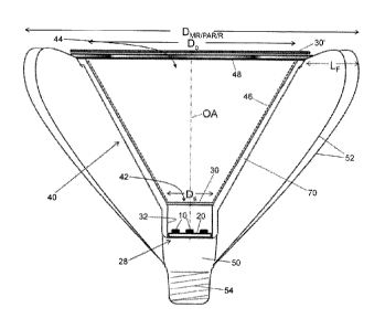
diffuser at the exit
aperture of the pillbox, the light that is formed into a beam by the beam-
forming optical system
of the directional lamp is not mixed or only partially mixed. To provide
additional light mixing, a
light shaping diffuser is suitably located distal from the LED die plane, for
example near or
beyond the exit aperture of the beam forming optical system. If the diffuser
is beyond the exit
aperture of the beam-forming optical system, then since the light rays
incident on the diffuser are
the formed beam which is substantially collimated by the beam-forming optics,
the diffuser can
be selected to be designed to operate at high efficiency (-92%, or more
preferably >95%, or even
more preferably >98%) for a collimated beam. The reduced number of reflections
along with
optimal diffuser efficiency results in significant increase in overall optical
efficiency (>90%).
[0047] Another aspect of the design of the disclosed directional lamps relates
to heat sinking.
The optical designs disclosed herein enable: (i) the output aperture of the
beam-forming optics to
19
CA 2786510 2017-04-13
236548
be reduced in size for a given beam angle; and (ii) the length of the lamp
including the disc (or
other extended light emission area) light source and the beam-forming optics
to be substantially
reduced while providing well-mixed light. The latter benefit results from the
reduction of the
length constraint on the beam-forming optics and the low profile of the light
source. Because of
these benefits, it is possible to surround substantially the entire lamp
assembly, including the
beam-forming optics, with a heat sink that includes fins surrounding the beam-
forming optics,
while providing good beam control, high optical efficiency and well-mixed
color in the beam.
A synergistic benefit of the resulting large heat sink surface area is that
the improved heat
dissipation enables design of a smaller diameter low profile disc light
source, which in turn
enables further reduction in the beam FWHM.
[0048] The disclosed designs enable construction of lamps that meet the
stringent size, aspect
ratio, and beam FWHM constraints of the MR/PAR/R standards, as is demonstrated
herein by
the reporting of actual reduction to practice of LED-based directional lamps
constructed using
design techniques disclosed herein. The actually constructed directional lamps
both conform
with the MR/PAR/R standard and provides excellent CRI characteristics.
Moreover, the
disclosed design techniques provide principled scaling to larger or smaller
lamp sizes and beam
widths while still conforming with the MR/PAR/R standard, enabling convenient
development
of a family of MR/PAR/R lamps of different sizes and beam widths.
[0049] With reference to FIGURES 1-15, some lighting apparatus embodiments
disclosed
herein employ a light-mixing cavity that includes a planar light source. As
shown in FIGURES
1-15, the planar light source includes one or more one light emitting diode
(LED) devices 10,
12, 14 disposed on a planar reflective surface 20. The planar reflective
surface 20 illustrated in
the embodiments of FIGURES 1-15 has a circular perimeter, and may be, for
example, a printed
circuit board (PCB), metal core printed circuit board (MC-PCB), or other
support. FIGURES 1-9
illustrate various arrangements of small LED devices 10. FIGURE 1()
illustrates an arrangement
of four large LED devices 14. FIGURES 11 and 12 illustrate arrangements of
five medium-sized
LED devices 12 and four medium-sized LED devices 12, respectively. FIGURES 13
and 14
illustrate arrangements of small and large LED devices 10, 14. In color mixing
embodiments, the
different LED devices 10, 14 may be of different types ¨ for example, the
small LED
CA 2786510 2017-04-13
236548
devices 10 may be bluish-green LED devices while the large LED devices 14 may
be red LED
devices, or vice versa, with the bluish-green and red spectra selected to
provide white light when
color mixed by a strong diffuser as described herein. Although in FIGURES 13
and 14 the LED
devices 10, 14 of different types (e.g., different colors) have different
sizes, it is also
contemplated for the LED devices of different types to have the same size. As
shown in FIGURE
15, in yet other embodiments the pattern of one or more LED devices may
include as few as a
single LED device, such as the illustrated single large LED device shown by
way of example in
FIGURE 15.
[0050] With reference to FIGURES 16-18, in other variant embodiments of the
light source,
the planar reflective surface has a perimeter other than circular. FIGURE 16
illustrates three
large LED devices 14 disposed on a planar reflective surface 22 having a
polygonal (more
particularly hexagonal) perimeter by way of example. FIGURE 17 illustrates
seven small LED
devices 10 disposed on the planar reflective surface 22 with hexagonal
perimeter by way of
example. FIGURE 18 illustrates five medium sized LED devices 12 disposed on a
planar
reflective surface 24 having a rectangular perimeter by way of example.
[0051] As used herein,
the term "LED device" is to be understood to encompass bare
semiconductor chips of inorganic or organic LEDs, encapsulated semiconductor
chips of
inorganic or organic LEDs, LED chip "packages" in which the LED chip is
mounted on one or
more intermediate elements such as a sub-mount, a lead-frame, a surface mount
support, or so
forth, semiconductor chips of inorganic or organic LEDs that include a
wavelength-converting
phosphor coating with or without an encapsulant (for example, an ultra-violet
or violet or blue
LED chip coated with a yellow, white, amber, green, orange, red, or other
phosphor designed to
cooperatively produce white light), multi-chip inorganic or organic LED
devices (for example,
a white LED device including three LED chips emitting red, green, and blue,
and possibly other
colors of light, respectively, so as to collectively generate white light), or
so forth. In the case
of color-mixing embodiments, the number of LED devices of each color is
selected such that the
color-mixed intensity has the desired combined spectrum. By way of example, in
FIGURE 13
the large LED device 14 may be selected to emit red light and the LED devices
10 may be
selected to emit bluish or bluish-greenish or white light, and the selection
of nine LED devices
21
CA 2786510 2017-04-13
236548
and only one LED device 14 may suitably reflect a substantially higher
intensity output for
the LED device 14 as compared with the LED devices 10 such that the color-
mixed output is
white light having the desired spectral distribution.
[0052] With reference to FIGURES 19 and 20, an illustrative embodiment of a
pillbox disc
includes a low profile light-mixing cavity in close proximity to the LEDs. A
planar light source
28 as shown in FIGURE 7 forms the "bottom" of the pillbox, and a planar light
transmissive and
light scattering diffuser 30 of maximum lateral dimension L is arranged
parallel with the planar
light source and spaced apart from the planar light source 28 by a spacing S
to form the "top" of
the pillbox. Reflective sidewalls 32 connecting a perimeter of the planar
light source 28 and a
perimeter of the diffuser 30. In some embodiments the diffuser 30 is omitted
in favor of a
diffuser located outside the Fresnel lens or elsewhere as part of the beam
forming optics ¨ in
such embodiments, the reflective sidewalls 32 may terminate at and define an
entrance aperture
for the beam-forming optics, or the reflective sidewall may remain to define
the entrance
aperture. In FIGURES 19 and 20, the reflective sidewalls 32 are shown in
phantom to reveal
internal components. Moreover, it is to be understood that it is the inside
sidewalls (that is, the
sidewalls facing into the light-mixing cavity) that are reflective ¨ the
outside sidewalls may or
may not be reflective. Thus, a reflective cavity is defined by the reflective
surface 20 of the
planar light source 28 and the reflective sidewalls 32. This reflective cavity
has the diffuser 30
filling its output aperture ¨ in other words, light exits from the reflective
cavity via the diffuser
30. FIGURE 19 shows the assembled light-mixing cavity including the diffuser
30 disposed
over and filling the output aperture of the reflective cavity, while FIGURE 20
shows the
reflective cavity with the diffuser 30 removed to reveal the output aperture
34 of the reflective
cavity.
[0053] The illustrative light-mixing cavities employ the planar light source
28 shown in
FIGURE 7. However, it is to be appreciated that any of the planar light
sources shown in any of
FIGURES 1-18 may be similarly used in constructing a light-mixing cavity. In
the case of the
planar light sources of FIGURES 16 and 17, the diffuser optionally has a
hexagonal perimeter to
match the hexagonal perimeter of the hexagonal reflective surface 22, and the
sidewalls suitably
have a hexagonal configuration connecting the hexagonal perimeter of the
reflective surface 22
with the hexagonal perimeter of the diffuser, or the diffuser and the sidewall
may have a circular
22
CA 02786510 2012-07-05
WO 2011/085146 PCT/US2011/020442
236548
configuration to match the exit aperture of the lamp. Similarly, in the case
of the planar light
source of FIGURES 18, the diffuser optionally has a rectangular or a square
shaped perimeter to
match the rectangular or square perimeter of the reflective surface 24, and
the sidewalls suitably
have a rectangular or square configuration connecting the rectangular or
square perimeter of the
reflective surface 22 with the rectangular or square perimeter of the
diffuser, or the diffuser and
the sidewall may have a circular configuration to match the exit aperture of
the lamp.
[0054] Existing light-mixing cavities (not those illustrated herein) typically
rely upon multiple
light reflections to achieve light mixing. Toward this end, existing light-
mixing cavities employ a
substantial separation between the light source and the output aperture such
that a light ray
makes numerous reflections, on average, before exiting the light-mixing
cavity. In some existing
light cavities, additional reflective pyramids or other reflective structures
may be employed,
and/or the output aperture may be made small, so as to increase the number of
reflections a light
ray undergoes, on average, before exiting via the aperture of the light-mixing
cavity. Existing
light-mixing cavities are also typically made "long", that is, have the large
ratio Dspc/Ap where
Dspc is the separation between the light source and the aperture and Ap is the
aperture size. A
large ratio Dspc/Ap has two effects that are conventionally viewed as
beneficial: (i) the large
ratio Dspc/Ap promotes multiple reflections and hence increases the light
mixing; and (ii) in the
case of a spot lamp or other directional lamp the large ratio Dspc/Ap promotes
partial
collimation of the light by the reflective sidewalls of the light-mixing
cavity, and the partial
collimation is expected to assist operation of the beam-forming optics. Said
another way, a large
ratio Dspc/Ap implies a narrow columnar light-mixing cavity having the light
source at the
"bottom" of the narrow column and the output aperture at the "top" of the
narrow column ¨ the
narrow reflective column provides partial collimation of light through a large
number of
reflections.
[0055] The light-mixing cavities disclosed herein employ a different approach,
in which the
diffuser 30 is the primary light-mixing element. Toward this end, the diffuser
30 should be a
relatively strong diffuser. For example, in some embodiments, such as a spot
lamp, the diffuser
has a diffusion angle of at least 5-10 degrees, and in some embodiments, such
as a flood lamp,
has a diffusion angle of 20-80 degrees. A higher diffusion angle tends to
provide better light
23
CA 02786510 2012-07-05
WO 2011/085146 PCT/US2011/020442
236548
mixing; however, a higher diffuser angle may also produce stronger
backscattering of light back
into the optical cavity resulting in greater absorption losses. In the case of
a low profile light-
mixing cavity, the reflective cavity formed by the reflective surface 20 and
the sidewalls 32 is
not a substantial contributor to the light mixing. Indeed, there arc
advantages in having the
average number of reflections of a light ray in the reflective cavity be
small, e.g. zero, or one, or
at most a few reflections on average, since each reflection entails some
optical loss due to
imperfect reflectivity of the surfaces. Another advantage is that the
reflective cavity can be made
low-profile, that is, can have a small ratio S/L. Making the ratio S/L small
reduces the number of
average reflections from the side wall. In some embodiments, the ratio S/L is
less than three. In
some embodiments, the ratio S/L is less than or about 1.5 (which is estimated
to provide an
average number of reflections per light ray of between zero and one). In some
embodiments, the
ratio S/L is less than or about 1Ø
[0056] A small number of reflections, such as is achieved by a low-profile
reflective cavity with
small ratio S/L, reduces or eliminates the partial collimation of the light
achieved by a "longer"
reflective cavity. Conventionally, this is considered problematic for a spot
lamp or other
directional lamp.
[0057] With continuing reference to FIGURE 19 and with further reference to
FIGURES 21
and 22, three variant light-mixing cavities of the pillbox type are shown.
FIGURE 19 shows a
light-mixing cavity with intermediate ratio S/L. FIGURE 21 shows a light-
mixing cavity with a
larger spacing S' between the diffuser 30 and the planar light source 28, thus
leading to a larger
ratio S'/L. FIGURE 22 shows a light-mixing cavity with a smaller spacing S"
between the
diffuser 30 and the planar light source 28.
[0058] In general, for high optical efficiency from a pillbox-type light-
mixing cavity it is
desired for S/L<3, and more preferably S/L less than or about 1.5 (typically
leading to about 0-1
reflections per light ray, on average), and still more preferably S/L less
than or about 1Ø Still
smaller values for the ratio S/L are also contemplated, such as is shown in
FIGURE 22. The
minimum value for the ratio S/L is determined by the spatial and angular
uniformity of the
luminance and color at the output of the light-mixing cavity, which is limited
by the spacing of
24
CA 02786510 2012-07-05
WO 2011/085146 PCT/US2011/020442
236548
the LED devices and the diffusion angle of the diffuser 30. Advantageously,
the angular
distribution of luminance generated by the LED devices is typically relatively
broad ¨ for
example, a typical LED device typically has a Lambertian (i.e., cos(0))
luminance distribution
for which the half-width-at-half-maximum (HWHM) is 60 (i.e., cos(60 )=0.5).
For reasonably
closely-spaced LED devices such as those illustrated in FIGURES 1-14 or 16-18,
a diffuser with
diffusion angle of about 5-10 or larger is sufficient for providing uniform
illumination output
from the multiple LED devices across the area of the diffuser 30 without
reliance upon multiple
light ray reflections within the reflective cavity if S/L is greater than or
about 1Ø In the case of
the single LED device embodiment of FIGURE 15, the minimum value of the ratio
S/L is
preferably selected to ensure that the single LED device 14 illuminates the
whole area of the
diffuser 30 so as to generate uniform illumination output across the area of
the diffuser 30. If the
single LED device emits light having an approximately Lambertian intensity
distribution, then
S/L greater than or about 1.0 is again sufficient.
[0059] The light-mixing cavities disclosed herein with reference to FIGURES 1-
22 are suitable
for use in any application in which a low profile light source generating
uniform illumination
across an extended lateral area, substantially without collimation of the
output light, is of value.
These light-mixing cavities are also useful to provide such a disc light
source in which LED
devices of different colors or color temperatures (in the case of white LED
devices) are color
mixed to achieve a desired spectrum, such as white light or white light with a
specified color
rendering index (CRI), color temperature, or so forth. The light-mixing
cavities disclosed herein
with reference to FIGURES 1-22 are low profile (that is, have S/L<3, and more
preferably S/L
less than or about 1.5, and still more preferably S/L less than or about 1.0)
and are useful for
applications such as undercabinet lighting, theater floor lighting, or so
forth, or in any lamp or
lighting system where a compact size and weight in combination with good beam
control and
good color quality are important.
100601 With reference to FIGURE 23, the light-mixing cavities disclosed herein
with reference
to FIGURES 1-22 are suitable for use in a directional lamp. FIGURE 23
illustrates a directional
lamp including a low profile light-mixing cavity formed by the planar light
source 28, the
diffuser 30, and connecting reflective sidewalls 32 (i.e., as shown in more
detail in FIGURE 19)
CA 2786510 2017-04-13
236548
which serves as light input to beam forming optics 40. The beam forming optics
40 include an
entrance aperture 42 which is filled by or defined by the diffuser 30. The
entrance aperture 42
has maximum lateral dimension D, that is approximately the same as the maximum
lateral
dimension L of the diffuser 30. The beam forming optics 40 also have an exit
aperture 44 that
has maximum lateral dimension Dõ. The illustrative directional lamp of FIGURE
23 has
rotational symmetry about an optical axis OA, and the apertures 42, 44 have
circular perimeters
with the circular perimeter of the entrance aperture 42 substantially matching
the circular
perimeter of the diffuser 30. Accordingly, the maximum lateral dimensions D8,
Dõ, and L are all
diameters in this illustrative embodiment. The illustrative beam-forming
optics 40 include a
conical light-collecting reflector 46 extending from the entrance aperture 42
to the exit aperture
44, and a Fresnel lens 48 (which optionally can be replaced by another type of
lens such as a
convex lens, holographic lens, or so forth) disposed at the exit aperture 44.
More precisely, the
conical reflector 46 has the shape of a frustum of a cone, that is, the shape
of a cone cut by two
parallel planes namely the planes of the entrance and exit apertures 42, 44.
Alternately, the
conical collecting reflector 46 may be replaced by a parabolic or compound
parabolic or other
conic section reflector. Due to the nearly ideal disc-shaped light source, the
beam can be formed
with high efficiency and excellent beam control by imaging the disc light
source into the optical
far field using a Fresnel or other lens at the output aperture of the lamp. To
achieve imaging of
the disc light source at infinity the disc light source should be located at
the focus of the
imaging lens 48. Such an arrangement forms a beam that contains all of the
face lumens within
the beam lumens in an ideal situation, or nearly all of the face lumens within
the beam lumens
in a practical lamp, providing a beam pattern with abrupt edges. If, instead,
the arrangement
is slightly defocused, for example with the disc light source located at a
distance from the
imaging lens 48 that is within plus or minus 10% of the lens focal length but
not precisely at
the lens focal length, then the defocusing produces a light beam that still
has a narrow FVVHM
but in which intensity edges are smoothed or eliminated. Due to the nearly
Lambertian angular
intensity distribution of the LEDs, most of the light reaches the lamp
aperture without
reflection from the conical reflector, so that the primary purpose of the
reflector is to gather
the small amount of light from the high angles (in other words, is arranged to
reflect light from
the light source that misses the lens 48 into the lens 48 to contribute to the
light beam). In
some embodiments, the exit aperture of the collecting reflector is at least
three times larger
than the entrance aperture of the collecting reflector. In some embodiments
the exit aperture
of the collecting reflector is at least five times larger than the entrance
aperture of the collecting
reflector. In some embodiments the exit aperture of the collecting reflector
is at least eight
times larger than the entrance aperture of the collecting reflector. In
contrast, the primary
26
=
CA 02786510 2012-07-05
WO 2011/085146 PCT/US2011/020442
236548
purpose of the reflector in conventional beam-forming optics is to create the
beam pattern. Since
the primary purpose of the reflector 46 of FIGURE 23 is to gather high-angle
light, rather than
providing the primary control of the beam shape, the traditional parabola or
CPC may be
replaced by a less complex design such as the illustrative conical reflector
46, with a significant
advantage that the cone may be constructed from a variety of flat,
inexpensive, coated materials
having extremely high optical reflectivity (90% or higher).
[0061] As used herein, the "beam-forming optics" or "beam-forming optical
system" includes
one or more optical elements configured to transform the illumination output
from the entrance
aperture 42 into a beam with specified characteristics, such as a specified
beam width
represented by the full width at half maximum (FWHM) of the beam, a specified
beam lumens
which is the integral of the lumens over the beam within the FWHM, a specified
minimum
CBCP, or so forth.
[0062] The directional lamp of FIGURE 23 further includes heat sinking. To
obtain a high
intensity light beam, the LED devices 10 should be high power LED devices,
which typically
include LED chips driven at high current of order 100 to 1000 mA, or higher,
per LED chip.
Although LEDs generally have very high luminous efficacy of about 75 to 150
LPW (i.e.,
lumens per watt), this is still only about one-fourth to one-half of the
efficacy of an ideal light
source, which would provide about 300 LPW. Any power supplied to the LED that
is not
radiated as light is dissipated from the LED as heat. As a consequence, a
substantial amount of
heat, typically one-half to three-quarters of the power supplied to each LED,
is generated at the
planar light source 28. Moreover, LED devices arc highly temperature-sensitive
as compared
with incandescent or halogen filaments, and the operating temperature of the
LED devices 10
should be limited to around 100-150 C, or preferably lower. Still further,
this low operating
temperature in turn reduces the effectiveness of radiative and convective
cooling. To provide
sufficient radiative and convective cooling to meet these stringent operating
temperature
parameters, it is recognized herein that heat sinking disposed solely around
the planar light
source 28 is likely to be insufficient. Accordingly, as shown in FIGURE 23,
the heat sinking
includes a main heat sinking body 50 disposed proximate to (i.e.,
"underneath") the planar light
source 28, and heat sinking fins 52 (which are optionally replaced by heat
sinking rods or other
27
CA 02786510 2012-07-05
WO 2011/085146 PCT/US2011/020442
236548
structures with large surface area) which extend radially outside of the beam-
forming optics 40.
Even if active cooling in form of a fan, a blower, or a phase-changing liquid
is used to enhance
the removal of heat from the LEDs, the amount of heat removal is still usually
proportional to the
available surface area of the heat transfer device surrounding the LEDs, so
that providing for a
large heat transfer area is generally desirable.
[0063] The illustrated directional lamp of FIGURE 23 is of an MR/PAR/R design,
and toward
this end includes a threaded Edison base 54 designed to mechanically and
electrically connect
with a mating Edison-type receptacle. Alternatively, the base can be a bayonet-
type base or other
standard base chosen to comport with the receptacle of choice. Insofar as the
MR/PAR/R
standard imposes an upper limit on the lamp diameter Dmrt/pAR/R, it will be
appreciated that there
is a trade-off between the lateral extent LF of the heat-sinking fins 52, on
the one hand, and the
diameter Do of the optical exit aperture 44 on the other hand.
[0064] The directional lamps disclosed herein are constructed based on
Equations (2) and (3),
so as to match the etendue and skew invariants for the entrance and exit
apertures 42, 44. Said
another way, the directional lamps disclosed herein are constructed based on
Equations (2) and
(3) so as to match the etendue and skew invariants for (i) the source light
distribution output by
the entrance aperture 42 and (ii) the light beam intended to emanate out of
the exit aperture 44.
[0065] Considering first the etendue invariance, Equation (2) includes four
parameters: output
half-angle 00 of the beam (which is one-half the desired FWHM angle); half-
angle 0, of the light
distribution at the entrance aperture 42; and the entrance and exit aperture
diameters Dõ Do. Of
these, the output half-angle 00 of the beam is a target beam half-angle that
the directional lamp is
to produce, and so it can be considered to be the result of the other 3
parameters. Exit aperture Do
should be made as small as practicable in order to maximize the lateral extent
LF of the
heat-sinking fins 52 to promote efficient cooling. The half-angle 0, of the
light distribution at the
entrance aperture 42 is typically about 60 (corresponding to approximately a
Lambertian
intensity distribution), so that the most influential design parameters for
the optical system are
the entrance aperture diameter D, which, together with Oõ determines the
source etendue, and
exit aperture diameter Do. For a narrow beam angle, the source etendue should
be made as small
28
CA 02786510 2012-07-05
WO 2011/085146 PCT/US2011/020442
236548
as possible, that is, D, and Os should be minimized, and the exit aperture
diameter Do should be
maximized. However, these design parameters are to be optimized under
constraints including:
the maximum aperture diameter Do imposed by the MR/PAR/R diameter standard
DMR/PAR/R; the
heat sinking for the thermal load of LED devices 10 sufficient to generate the
desired light beam
intensity which imposes a minimum value on the fins lateral extent LF; a
minimum value
constraint for the entrance aperture diameter D, imposed by thermal,
mechanical, electrical, and
optical limits on how closely the LED devices 10 can be spaced on the planar
reflective surface
20; and a lower limit on the source half-angle Os imposed by the low-profile
light-mixing source
which does not provide partial collimation by multiple reflections, or by the
LED intensity
distribution itself.
100661 Turning to the skew invariance, the use of a disc light source (that
is, a light source
having a disc-shaped light emission area, optionally discretized into one or
more individual LED
devices disposed on a reflective circuit board or other support) enables exact
matching of skew
invariance with that of the exit aperture 44, which provides the possibility
of containing all of the
face lumens within the beam lumens in an ideal situation, or nearly all of the
face lumens within
the beam lumens in a practical lamp, providing the possibility of an extremely
abrupt edge of the
beam pattern. The Fresnel lens 48 (or convex lens, holographic lens, compound
lens, or so forth)
filling the exit aperture and cooperating with the conical reflector 46 (or
other collecting
reflector) may be used to generate an image in the optical far field of the
illumination output at
the entrance aperture 42 to produce a beam pattern with a sharp cut-off at the
edge of the beam.
Alternately, the Fresnel lens (or convex lens, holographic lens, compound
lens, or so forth)
cooperating with the conical reflector 46 (or other collecting reflector) may
be used to generate
an image of the illumination output at the entrance aperture 42 that is de-
focused in the far field
to produce a beam pattern with a gradual cut-off at the edge of the beam. A de-
focused
placement of the Fresnel lens 48 may also be used to supplement the light
mixing that is
provided predominantly by the diffuser, since the images of the discrete LED
light sources are
thus out of focus in the far field such that the interstitial spaces between
the LEDs appear in the
far-field beam pattern to be filled in by the light from adjacent LEDs.
29
CA 2786510 2017-04-13
236548
[0067] It will be noted that the design considerations do not include any
limitation on the
"height" or "length" of the lamp along the optical axis OA. (The optical axis
OA is defined by
the beam forming optical system, and more particularly by the optical axis of
the imaging lens
48 in the embodiment of FIGURE 23). The only limitation imposed on the height
or length is
by the focal length of the lens 48, which can be small for a Fresnel lens or a
short focal length
convex lens. In some embodiments, the lens has an f-number N=f/D of less than
or about one
whe,re N is the f-number, f is the focal length of the lens, and D is a
maximum dimension of the
entrance pupil of the lens. Moreover, there is no limitation imposed on the
shape of the reflector
46 ¨ for example, the illustrated conical reflector 46 could be replaced by a
parabolic
concentrator, a compound parabolic concentrator, or so forth.
[0068] With continuing reference to FIGURE 23, in some embodiments a diffuser
30' is
disposed outside the Fresnel lens 48, that is, such that light from the
pillbox passes through the
Fresnel lens 48 to reach the diffuser 30'. As noted previously, if the
diffuser 30 at the entrance
aperture 42 (that is, at the "top" of the pillbox) is employed alone, then
heavy diffusion is
typically employed to achieve adequate light mixing. However, this can lead to
back-reflections
off the diffuser 30 and consequent increased light losses. Adding the diffuser
30' located outside
of the Fresnel lens 48 can provide additional light mixing, enabling the
diffusion strength of the
diffuser 30 at the entrance aperture 42 to be reduced, or the diffuser 30' may
provide all of the
required light mixing so that the diffuser 30 at the entrance aperture 42 may
be eliminated. For
the diffuser 30' located outside the Fresnel lens 48, the incident light rays
are nearly collimated,
and so the diffuser 30' can be selected to be a diffuser designed to operate
at high efficiency
(-92%, and more preferably >95%, and still more preferably >98%) for
collimated input light.
For example, in some embodiments employing only the diffuser 30', but not the
diffuser 30, the
spatial and angular non-uniformity of the luminous intensity and color is
mixed to a substantially
uniform distribution by the diffuser 30' which is a single-pass light
diffuser. Some suitable
single-pass light diffusers designed to provide a selected output (diffused)
light scattering
distribution FWHM include Light Shaping Diffuser material produced by
Luminit, LLC,
having 85-92% transmission of visible light and providing diffusion of the
transmitted light with
a light scattering distribution (for collimated input light) of between 10 and
80 FAN HM,
depending on the choice of material. Another suitable diffuser material is
ACELTm light
diffusing material (available from Bright View Technologies). These
illustrative designed single
pass diffuser materials are not bulk diffusers in which light scattering
particles are dispersed in a
CA 02786510 2012-07-05
WO 2011/085146 PCT/US2011/020442
236548
light-transmissive binder, but rather are interface diffusers in which the
light diffusion occurs at
an engineered interface having light scattering and/or refractive
microstructures engineered to
provide the target light scattering distribution for input collimated light.
Such diffusers are well
suited for use as the diffuser 30 that passes the light beam of relatively
small FWHM. (In
contrast, light rays incident on such a designed diffuser that are not nearly
collimated would be
more likely to be scattered into higher angles than desired). In other words,
there is a synergistic
benefit to (i) placing the diffuser 30' after the imaging lens 48 so as to
receive an input light
beam of relatively small FWHM and (ii) using an engineered interface diffuser
or other
single-pass diffuser which advantageously has low backreflection. The reduced
number of
reflections along with optimal diffuser efficiency provided by the diffuser
30' located beyond the
beam-forming optics and engineered to provide a designed light scattering
distribution FWHM
results in significant increase in overall optical efficiency (>90%). In some
embodiments, the
diffuser 30 is included while the diffuser 30' is omitted. In some
embodiments, both diffusers 30,
30' are included.
100691 In yet other embodiments, the diffuser 30 at the entrance aperture 42
is omitted and the
diffuser 30' outside the Fresnel lens 48 is included. In these embodiments in
which the diffuser
30 is omitted, the cone of the reflector 46 is optionally extended to the LED
die level ¨ that is,
the planar light source 28 is optionally arranged coincident with the entrance
aperture 42, and the
reflective sidewalls 32 are optionally omitted along with the omitting of the
diffuser 30. In such
embodiments, the diffuser 30' is relied upon to provide the light mixing. In
any of the
embodiments, the lens may also be defocused to provide additional light
mixing.
100701 These various arrangements are further shown in FIGURES 24A, 24B, and
24C.
FIGURE 24A diagrammatically shows a lamp containing a light engine LE, beam
forming optics
BF including a conical reflector and lens, and the optically diffusing element
30 located adjacent
an optically reflective side wall. In this embodiment the optically diffusing
element 30 is a heavy
diffuser, and there is no diffuser at the output aperture. FIGURE 24B
diagrammatically shows a
lamp containing the light engine LE, beam forming optics BF including a
conical reflector and
lens, and both (i) the optically diffusing element 30 located adjacent an
optically reflective side
wall and (ii) and the optically diffusing element 30' located near the output
aperture of the
31
CA 02786510 2012-07-05
WO 2011/085146 PCT/US2011/020442
236548
MR/PAR/R lamp. In this embodiment the optically diffusing element 30 is a soft
diffuser, as
further diffusion is provided by the light shaping diffuser 30' at the output
aperture of the lamp.
FIGURE 24C diagrammatically shows a lamp containing the light engine LE, beam
forming
optics BF including a conical reflector and lens, and the light shaping
optically diffusing element
30' located near the output aperture of the MR/PAR/R lamp. In the embodiment
of FIGURE 24C
the light diffusing element 30 is omitted.
[0071] With reference to FIGURES 25-27, an advantage of the illustrated
conical reflector 46 is
that it can simplify manufacturing, reduce cost, and improve efficiency. For
example, FIGURES
25-27 illustrate how the conical reflector 46 can be a planar reflective sheet
covering an inside
conical surface of a conical former. FIGURE 25 shows a planar reflective sheet
46p having
rounded lower and upper edges 60, 62 corresponding to the entrance and exit
apertures 42, 44,
respectively, and side edges 64, 66. As shown in FIGURE 26, the planar
reflective sheet 46p can
be rolled to form the conical reflector 46, with the side edges 64, 66 joined
at a connection 68
(which optionally may include some overlap of the side edges 64, 66), which
then may be
inserted into a conical former 70 as illustrated in FIGURE 27. With reference
back to FIGURE
23, the conical former 70 may, for example, be a conical heat-sinking
structure 70 that also
supports the heat-sinking fins 52. In addition to the simplification and cost-
reduction in
manufacturing, the conical reflector also enables the use of coated reflector
materials having
extremely high optical reflectivity in the visible, such as a coated aluminum
material named
Miro produced by ALANOD Aluminium-Veredlung GmbH & Co. KG having about 92-98%
visible reflectance; or polymer film named Vikuiti produced by 3M having about
97-98% visible
reflectance.
[0072] FIGURES 28 and 29 illustrate computed values for the FWHM angle of the
beam
pattern in degrees (on the ordinate axis) versus the entrance aperture
diameter Ds for various
MR/PAR/R lamp designs (on the abscissa axis). In FIGURE 28, it is assumed that
the exit
aperture of the lamp has the maximum possible value equal to the diameter of
the lamp envelope
itself, Do=DMRIPAR/R, e.g. D0=120 mm for a PAR38 lamp; while in FIGURE 29, it
is assumed
that the exit aperture of the lamp is only 75% of the maximum possible value,
e.g. D0=90 mm for
a PAR38, in order to allow an annular space for heat sinking fins 52 (see
FIGURE 23), or other
32
CA 2786510 2017-04-13
236548
high-surface area structures for promoting heat removal by radiation and
convection, around the
beam-forming optics 40. In FIGURES 28 and 29 plots are shown for MR16, PAR20,
PAR30,
and PAR38, where the numbers indicate the MR/PAR/R lamp diameter in eights of
an inch (thus,
MR16 has a 16/8=2 inch diameter, for example). The plots assume 2x0, =120",
corresponding
to a Lambertian intensity distribution for the LED array.
[0073] FIGURE 30 plots the beam output angle FWHM (that is, 2 x 0õ) as the
ordinate versus
the ratio Ds/D0 (or, equivalently, L/D(,) as the abscissa. This plot also
assumes 2x0s =120',
corresponding to a Lambertian intensity distribution for the LED array.
[0074] With reference to FIGURES 31A and 31B, in some embodiments the Fresnel
lens 48
and the diffuser 30' located at the exit aperture of the collecting reflector
46 are combined in a
single optical element. In FIGURE 31A, an optical element 100 includes a
lensing side 102 that
is the light-input side and is engineered by laser etching or another
patterning technique to define
a Fresnel lens suitably serving as the Fresnel lens 48, and also includes a
light diffusing side 104
that is the light exit side and is engineered by laser etching or another
patterning technique to
define a single-pass interface diffuser suitably serving as the light-mixing
diffuser 30'. Said
another way, the light mixing diffuser comprises an interface diffuser 104
formed into a principal
surface of the lens 100 of the beam forming optical system. In the
configuration of FIGURE
31A, the diffusing side 104 advantageously passes light after it is formed
into a beam by the
lensing side 102. Alternatively, as shown in FIGURE 31B an optical element 110
has the same
structure as the optical element 100, but the light diffusing side 104 is
arranged as the light input
side and the lensing side 102 is arranged as the light exit side.
The preferred embodiments have been illustrated and described. Obviously,
modifications and
alterations will occur to others upon reading and understanding the preceding
detailed
description. It is intended that the invention be construed as including all
such modifications
and alterations insofar as they come within the scope of the appended claims
or the equivalents
thereof.
33