Note: Descriptions are shown in the official language in which they were submitted.
CA 02787492 2012-07-18
WO 2011/102797 PCT/SE2011/050178
Method and arrangement at trucks for tipping a loading bin
TECHNICAL AREA
The present invention concerns a method for tipping a
loading bin arranged at a truck and a pivot arrangement
for the execution of the method according to the preamble
to the independent claims. The invention concerns also a
truck comprising such an arrangement.
THE PRIOR ART
Vehicles for heavy loads normally have a load carrier that
includes a loading bin, such as a loading bed, that can be
tipped backwards around a pivot arrangement and that is
supported by a load frame. For the dimensioning of the
load carrier and, in particular, the load frame for such
vehicles, not only the static maximal load must be taken
into account, but also the dynamic factors to which the
machine will be exposed while working with the load
carrier. In addition, the dimensioning of the load frame
must include also safety aspects. What is crucial to the
weight, dimension and cost of the load frame is the manner
in which the weight of the load is distributed over the
load frame. The term "forwards" in the following text will
be used to denote the direction from the rear of the
vehicle towards the front, i.e. the direction of travel of
the vehicle when in use. In the same manner, the term
"backwards" will be used to denote the opposite direction
from the front of the vehicle towards the rear, i.e. the
direction of travel when the vehicle reverses. The act of
tipping the loading bin will be denoted by "lifting
operation of the loading bed".
The support of the loading bin by one or several shock-
absorbing pads (buffers) arranged at the front of the load
frame and that are mechanically suspended in the direction
of pivoting (the direction of tipping) is known. In this
CA 02787492 2012-07-18
WO 2011/102797 PCT/SE2011/050178
2
manner the load is supported relative to the load frame at
the front edge of the loading bin and backwards, at the
pivot. The load-bearing wheels are mounted at the frame
between the front and rear points of attack of the load.
This means that the load frame must be dimensioned for
large bending loads, which requires large and heavy load
frames in order to ensure that the load frame is
sufficiently resistant to bending to withstand the bending
stresses that arise. This increases the deadweight of the
load frame, and increases costs.
In order to achieve lower bending stresses in the load
frame, the distribution of the load onto several shock-
absorbing buffers arranged at the load frame in the region
of the frame and the loading bin, and thus achieving a
broad distribution of load along the frame, is therefore
known. The problem is to achieve an optimal distribution
of the load along the frame whereby the buffers must be
correctly adjusted, which is difficult to achieve. The
load frame is, instead, overdimensioned. Also deformations
of the loading bin that arise through its use make
difficult an optimal distribution of load where several
buffers are used, and thus the resulting distribution of
the load is changed. If, in addition, one or several of
the buffers is wrongly adjusted or has been removed, the
weight of the load is distributed unevenly and in an
uncontrolled manner across the other buffers. In addition
to the fact that the load frame is overdimensioned,
monitoring and continuous adjustment of the buffers is
required in order to avoid the effect of increasing
bending stress, and this results in extra maintenance
costs.
There is thus a need within the industry to achieve an
improved load carrier.
CA 02787492 2012-07-18
WO 2011/102797 PCT/SE2011/050178
3
DESCRIPTION OF THE INVENTION
The aim of the invention is to achieve an arrangement and
a method by which the disadvantages of the prior art
technology are removed, or at least reduced.
According to a first aspect of the invention, this is
achieved through a pivot arrangement of the type described
in the introduction through characterising distinctive
features of the independent claim. Such a pivot
arrangement is adapted to be arranged at a load
arrangement for trucks including a load frame arranged to
support load in a loading bin that is arranged such that
it can be rotated through the pivot arrangement, whereby
the pivot arrangement is arranged to displace the
resulting point of attack of the loading bin during a
lifting operation of the loading bed. The pivot
arrangement is arranged at the rear end of the load frame.
By selecting the point of attack for the loading bin
during transport to be central over the load-bearing
wheels, it is possible to reduce bending stress in the
load frame caused by large bending and dynamic loads, and
the load frame can in this way be made slimmer and lighter.
According to a further embodiment, the pivot arrangement
comprises a first pivot joint, fixed at the frame in a
manner that allows it to rotate, a second pivot joint,
fixed at the loading bin in a manner that allows it to
rotate, whereby the first and the second pivot joints are
united with each other by an arm in a manner that allows
rotation. It is in this way possible to displace the
centre of pivoting of the loading bin during tipping, and
it is at the same time possible to change the distribution
of load during transport such that the greater part of the
load is transferred centrally over the beam for the rear
axle of the truck. The pivot arrangement is in this way
arranged to rotate the loading bin during a lifting
operation of the loading bed and in this way displace the
CA 02787492 2012-07-18
WO 2011/102797 PCT/SE2011/050178
4
point of attack of the loading bin. The first of the two
pivot joints of the pivot arrangement is jointed with the
frame, while the second is jointed with the loading bed.
Thus the pivot arrangement has two fixed points of
jointing. During a lifting operation of the loading bed,
the weight of the load is displaced from the first pivot
joint to the second pivot joint through the arm being
rotated. Through the second pivot joint having a fixed
point of support in the load frame on which the load rests
during transport and through it being located at a
considerable distance from the first pivot joint, the
bending stresses during transport are reduced.
In one preferred embodiment the pivot arrangement
comprises also stop means, arranged to limit the extent of
motion of the arm. It is therewith possible to control the
motion of the arm such that it stops the motion of the
pivot joint at a position at which the centre of pivoting
is displaced from the first pivot joint to the second
pivot joint.
According to a second aspect of the invention, this is
achieved through a truck of the type described in the
introduction through the characterising distinctive
features of the independent claim. Such a truck for heavy
transport may comprise a front part united with a rear
part comprising a load arrangement that includes a load
frame arranged to support a loading bin, whereby the
loading bin is arranged at the rear end of the load frame
such that it can be rotated, whereby the load frame
comprises a pivot arrangement as has been described above,
arranged to displace the resulting point of attack of the
loading bin during a lifting operation of the loading bed.
By displacing the resulting point of attack of the loading
bin during a lifting operation of the loading bed and at
the beginning of lift of the loading bed it is possible
not only to allow the greatest part of the weight of the
load to attack centrally over the rear axle beam during
CA 02787492 2012-07-18
WO 2011/102797 PCT/SE2011/050178
transport, but also that the point of attack of the
loading bin during tipping, i.e. the centre of pivoting of
the loading bin, is displaced to the rear end of the rear
part of the load frame during tipping. Thus we need to
5 consider nearly only the static load when dimensioning the
load frame, and this leads to savings in weight and costs
of the load frame. The solution gives levels of
dimensioning bending stress that are considerably lower
than those of the prior art technology. By arranging the
loading bin such that it balances at a position above or
in the vicinity of the rear of the rear axle beam during
the transport phase, it is possible to reduce the
dimensions of the load frame.
In one embodiment according to the invention the load
frame comprises a rearwards rear axle supporting a bogie
arrangement with two load-bearing wheel axles, provided
with wheels, arranged under the rear part of the load
frame. The advantage is that the loading bin is
distributed among four wheels, which can therefore be made
smaller in size and thus cheaper, and contribute to a
lower overall height of the vehicle.
According to a third aspect of the invention, this is
achieved through a method of the type described in the
introduction through the characterising distinctive
features of the independent claim. Advantageous
embodiments are described in the non-independent claims.
The method demonstrates the same advantages as have
already been described in the claims relating to the
arrangement.
DESCRIPTION OF DRAWINGS
The invention will be explained in detail below through
description of embodiments with reference to the attached
drawings, in which:
CA 02787492 2012-07-18
WO 2011/102797 PCT/SE2011/050178
6
Figure lA shows a side view of a truck with a lowered
loading bed with a pivot arrangement according to the
invention,
Figure 1B shows a side view of the truck in Figure lA in
the initial phase of a lifting operation of the loading
bed,
Figure 1C shows a side view of the truck in Figure lA in
the final phase of a lifting operation of the loading bed,
Figure 2 shows a view from above of the truck in Figure lA
without the loading bin,
Figure 3A shows a side view of the pivot arrangement at the
truck in Figure lA in greater detail,
Figure 3B shows a side view of the pivot arrangement in
Figure 1B in greater detail, and
Figure 3C shows a side view of the pivot arrangement in
Figure 1C in greater detail.
DETAILED DESCRIPTION OF EMBODIMENTS
The following description relates to both the method and
the pivot arrangement.
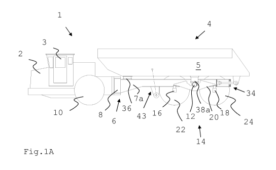
Figure 1A shows a side view of a truck 1 according to the
invention. The vehicle 1 in this case is a articulated
vehicle 1 and comprises a front part 2 with a driver cabin
3 and a rear part 4 with a load carrier. The load carrier
comprises a loading bin 5, in this case a loading bed. The
loading bin 5 makes contact with a load frame 6 which is
arranged horizontally relative to the central axis A at
the rear part 4, with two longitudinal beams, one of which
is indicated with 7a.
The front part 2 is united to the rear part 4 through a
control joint 8, in a manner that allows pivoting. The
front part 2 comprises a forwards load-bearing wheel axle
provided with one pair of wheels, one wheel of which is
indicated with 10. The rear part 4 comprises a rear axle
12 supporting a bogie arrangement 14 whereby the rear axle
CA 02787492 2012-07-18
WO 2011/102797 PCT/SE2011/050178
7
12 is fixed attached between the longitudinal beams 7a,
7b. The bogie arrangement 14 supports two load-bearing
wheel axles 16, 18, provided with wheels, that are
mutually united through a pendulum suspension arrangement,
comprising two pendulum arms on each side of the load
frame 6, one pendulum arm of which is indicated with 20.
The pendulum arms are fixed attached in a manner that
allows pendulum oscillation at the rear axle 12 such that
the resulting weight of the load attacks at a position
above the rear axle 12 on the load frame 6 when the
loading bed is in its lowered, transport, condition. The
pendulum arm 20 distributes the load equally between the
two wheel axles 16, 18 such that the weight of the load
during the transport phase is supported by the bogie
arrangement 14. The first rear axle 16, located closest to
the forwards part of the rear part of the vehicle,
supports a first pair of wheels, one wheel of which is
indicated by 22, and the second wheel axle 18, located
farthest back at the greatest distance from the front part
of the vehicle, supports a second pair of wheels, one
wheel of which is indicated by 24.
The loading bin 5 is arranged such that it can be pivoted
through it being fixed attached at a pivot arrangement (a
tipping arrangement) 34 arranged at the rear part of the
load frame 6, farthest away f rom the f ront part 2 of the
vehicle, arranged such that the load in the loading bin 5
can be tipped out of the same, behind the vehicle 1. The
loading bin 5 is supported when it makes contact with the
load frame 6, i.e. in the transport condition as shown in
figure 1A, by a first pair of shock-absorbing buffers on
each of the longitudinal beams 7a, 7b at the forward edge
of the load frame 6, one buffer of which is indicated by
36, and by a shock-absorbing arrangement 38 comprising a
second pair of shock-absorbing buffers on a beam between
the longitudinal beams 7a, 7b at the back of the load
frame 6, one buffer of which is indicated with 38a. The
shock-absorbing buffers 36, 38a, 38b are arranged to be
CA 02787492 2012-07-18
WO 2011/102797 PCT/SE2011/050178
8
deformed under changes of pressure and subsequently to
regain their original form when the pressure is reduced,
whereby the loading bin 5 still retains a soft support
during the initial phase of a lifting operation of the
loading bed. The buffers may be of, for example, rubber or
a polymer material. The second pair of buffers 38 at the
back of the load frame 6 is arranged above the attachment
point on the rear axle 12 of the relevant pendulum arm 20.
In this way the point of attack of the total weight of the
largest part of the load is located at a position
centrally above the rear axle 12 of the bogie arrangement,
during transport. Instead of a pair of buffers, one
extended buffer may be used, or a spring arrangement
comprising, for example, a metal spiral spring.
The load arrangement further comprises two hydraulic
cylinders arranged on each side of the beams 7a, 7b of the
load frame as tipping cylinders, each one of which has an
attachment 51 not only in front of the first back wheel 22
but also obliquely above in the loading bin 5 on the same
side of the vehicle 1. During unloading of the load (a
lifting operation of the loading bed), the position of the
loading bin 5 is changed by the use of the hydraulic
cylinders.
Due to the fact that the weight of the load is located
centrally over the rear axle 12 of the bogie arrangement
14, it does not contribute any bending torque to the load
frame 6 during transport when the loading bed is lowered
down onto the load frame 6. The load that dimensions the
load frame 6 will then be the load that is applied to the
load frame 6 during transport the forward buffers, and
through the tipping cylinders during a lifting operation
of the loading bed, since the vehicle 1 stands still
during lifting of the loading bed and thus an addition of
dynamic factors is not necessary during the dimensioning.
The truck is intended in particular to carry heavy loads
such as those arising during mining operations, road
CA 02787492 2012-07-18
WO 2011/102797 PCT/SE2011/050178
9
construction, etc., and it can be driven in a flexible
manner, by virtue of its design, also through narrow
passages in tunnels and other locations.
Figure 2 shows a view from above of the truck 1, without
the loading bin, whereby the rear part 4 of the vehicle
comprises a load frame 6. A shock-absorbing arrangement 38
is arranged on the load frame 6 at the back behind the
rear axle 12 of the bogie arrangement 14. The shock-
absorbing arrangement 38 comprises here two shock-
absorbing buffers 38a, 38b. The pivot arrangement 34 is
arranged farthest back on the load frame 6, farthest away
from the front part 2 of the vehicle.
The pivot arrangement comprises a first pivot joint (pivot
shaft) 40 perpendicular to the centre line A of the
vehicle attached at the frame in a manner that allows
rotation, and a second pivot joint (pivot shaft) 42, also
this perpendicular to the centre line of the vehicle and
attached at an attachment 44, which is also attached under
the loading bin (not shown in the drawings), in a manner
that allows rotation, the first and the second pivot
joints are furthermore united with each other in a manner
that allows rotation by an arm (a tipping beam) 46 that is
attached at both the first 40 and the second 42 pivot
joints in a manner that allows rotation, to form in this
way a double pivot joint (tipping joint). The arm 46 in
its resting position during transport has a longitudinal
extension that is parallel to the centre line of the load
arrangement when at rest. The pivot arrangement 34
comprises also stop means 48 (not shown in the drawings)
arranged to limit the extent of motion of the arm. The
attachment 44 is located behind the rear axle 12 of the
bogie arrangement 14 during transport.
Figures 1A-1C show the method according to the invention
as a sequence of a consecutive time points. Figures 3A-3C
CA 02787492 2012-07-18
WO 2011/102797 PCT/SE2011/050178
are side views of the pivot arrangement 34 corresponding
respectively to the sequence in figures 1A-1C.
Figure lA shows, as has been described above, a side view
5 of the truck 1 during its transport phase, which is the
same as the initial phase of a lifting operation of the
loading bed, the first phase of the sequence. The load
rests partly on the forward shock-absorbing buffers 36 and
partly on the rear shock-absorbing buffers 38a, 38b such
10 that the loading bin 5 essentially balances in a position
over the rear axle beam 12 of the bogie arrangement 14.
The pivot arrangement 34 is shown in Figure 3A in more
detail at the same instant. The pivot arrangement 34
comprising the first pivot joint 40, fixed at the frame in
a manner that allows it to rotate, the second pivot joint
42 fixed at the loading bin 5 by the attachment 44 in a
manner that allows it to rotate, whereby the pivot joints
are united to each other by the arm 46 in a manner that
allows rotation. The first 40 and the second 42 pivot
shafts of the pivot arrangement 34 are located in the same
line in the horizontal direction, parallel to the extent
of the beam 7a of the load frame: no weight is yet being
placed onto any one of the pivot joints (the pivot shafts)
40, 42. The stop means 48, arranged to control and limit
the extent of motion of the arm 46, is attached at
farthest back at the frame, and it comprises a frame with
an opening 49 through which the arm 46 passes. The opening
49 in this manner allows the arm 46 a freedom of movement
between the greatest extent of the arm 46 downwards
towards an impact beam 50a in the load frame during a
lifting operation of the loading bed, and upwards towards
a top beam 50b. Both the impact beam 50a and the top beam
50b pass transversely relative to the axis of symmetry A.
The arm 46 furthermore has a construction that resists
bending and prevents in this way the load from being
turned in the sideways direction during a lifting
operation of the loading bed. The arm 46 during the
transport phase or initial phase has a longitudinal extent
CA 02787492 2012-07-18
WO 2011/102797 PCT/SE2011/050178
11
parallel to the centre line A of the load arrangement and
is thus located in a central position in the opening 49 of
the stop means 48.
Figure 1B shows a side view of the truck 1 in Figure 1A
during the lifting phase of a lifting operation of the
loading bed, the second phase in the sequence, where the
load rests both on the rear shock-absorbing buffers 38a,
38b and on the first pivot joint 40. The pivot arrangement
34 is shown in Figure 3B in more detail at the same
instant.
A lifting operation of the loading bed is started by the
tipping cylinders 43 on each side of the load being
activated and starting to lift the loading bed. The point
of attack of the loading bin (the loading weight) is
displaced during this motion from a position above the
rear wheels to the first pivot joint 40, and then onwards
to the second pivot joint 42.
= When the loading bin 5 starts to rotate backwards, it
is lifted at its front edge such that it is no longer
in contact with the foremost pair of buffers 36 and
thus the loading bed instead is supported on the rear
pair of buffers 38a, 38b and at the first pivot joint
40.
= On further rotation upwards of the loading bin 5 it
no longer makes contact with the rear pair of buffers
38a, 38b but supports the loading bed partly at the
attachment 51 of the tipping cylinders and partly at
the first pivot joint 40, which becomes in this
manner the new point of attack of the load. The
loading bin 5 in this way rotates around the first
pivot joint 40.
= Subsequently, when the tipping cylinders 43 lift the
loading bin 5 further, the arm 46 rotates at the
first pivot joint 40 down towards the contact beam
50a where the rotation motion is stopped by the arm
CA 02787492 2012-07-18
WO 2011/102797 PCT/SE2011/050178
12
46 reaching the contact beam 50a at the stop means
48.
Figure 1C shows a side view of the truck in Figure 1A
during the tipping of the load, the final phase of a
lifting operation of the loading bed, the third phase of
the sequence; and Figure 3C shows a detailed side view of
the pivot arrangement 34 in Figure 1C at the same moment.
The point of attack of the load has now been displaced
from the first pivot joint 40 to the second pivot joint
42. The point of attack of the load is here transferred to
the second pivot joint 42, whereby the loading bin is
supported at the second pivot joint 42 and at the tipping
cylinders. The loading bin 5 now rotates solely around the
second pivot joint 42. During the continued extension of
the tipping cylinders up to the maximum tipping angle, the
load on the load frame 6 arises in this manner not only
through the cylinder attachments 51 but also through the
contact beam 50a for the tipping beam.
The invention is not limited to the embodiments shown: one
skilled in the arts can, naturally, modify it in a number
of ways within the scope of the invention defined by the
claims. Thus the vehicle 1 may also lack the bogie
arrangement that is shown in Figures 1A-1C. Further, the
front part 2 may comprise more than one forward wheel axle
and the rear part may comprise more than two wheel axles.
Furthermore, the front part of the truck may in various
embodiments be provided with a forward load-bearing wheel
axle with one or two pairs of wheels arranged under the
front section of the load frame, and the rear part may in
the same manner be provided with a bogie arrangement or
solely with one pair of wheels. In addition, in a further
embodiment, a vehicle with a rear axle with only one pair
of wheels may be used. The front part may be fixed united
with the rear part in further embodiments.