Note: Descriptions are shown in the official language in which they were submitted.
CA 02787511 2012-07-18
WO 2011/091110 PCT/US2011/021820
1
REFASTENABLE ABSORBENT ARTICLE
FIELD
The present disclosure generally relates to absorbent articles and methods for
manufacturing the same, and more particularly relates to refastenable and
disposable absorbent
articles and methods of manufacturing the same.
BACKGROUND
Many refastenable pull-on disposable absorbent articles, such as pants or
diapers, for
example, are provided to a consumer with fastening components initially
engaged. In such
structures, where first and second fasteners or a first fastener and a second
fastener, for example,
are initially engaged, the fastening components may form a pant comprising two
side seams, a
waist opening, and two leg openings. Consumers generally prefer that the side
seams of the pant
be easily openable and reliably recloseable. Initially engaged fastening
components, if designed
to deliver a low initial opening force, may also have a low subsequent opening
force after
reclosing of the side seams. The side seam reopening force of an opened and
reclosed side seam
(i.e., fasteners) is likely to require a lower force than the initial opening
force. Pants with a low
subsequent side seam opening force may lead to poor side seam strength and a
less secure
closure, since the same fasteners provide not only the initial, preferably low
opening force, but
also must provide adequate side seam strength after refastening. What is
needed is an
improvement over the foregoing.
SUMMARY
In one non-limiting embodiment, the present disclosure is directed, in part,
to an
absorbent article comprising a front waist region, a back waist region, a
crotch region disposed
between the front waist region and the back waist region, a front waist end
edge, a back waist end
edge, a longitudinal axis extending from a mid-point of the front waist end
edge to a mid-point of
the back waist end edge, a first longitudinally extending side edge, a second
longitudinally
extending side edge, an exterior surface, an interior surface, a topsheet, a
backsheet, and an
absorbent core disposed between the backsheet and the topsheet. A portion of
the front waist
region and a portion of the back waist region are joined in a surface to
surface relationship to
form a pant comprising a first permanent side edge seam and a laterally
opposed second
CA 02787511 2012-07-18
WO 2011/091110 PCT/US2011/021820
2
permanent side edge seam. The first and second permanent side edge seams
define an initial
waist opening circumference and a pair of leg openings. The absorbent article
comprises a first
fastening component comprising a first fastening surface and a first
attachment surface. The first
attachment surface is disposed on the interior surface or the exterior surface
of the absorbent
article in the front waist region. The absorbent article comprises a second
fastening component
comprising a second fastening surface. The second fastening component is
disposed on or forms
a portion of the same surface of the absorbent article on which the first
attachment surface is
disposed. The initial waist opening circumference formed by the first and
second permanent side
edge seams is configured to be opened. The first fastening surface and the
second fastening
surface are configured to be refastenably engaged and separated with each
other.
BRIEF DESCRIPTION OF THE DRAWINGS
The above-mentioned and other features and advantages of the present
disclosure, and the
manner of attaining them, will become more apparent and the disclosure itself
will be better
understood by reference to the following description of non-limiting
embodiments of the
disclosure taken in conjunction with the accompanying drawings, wherein:
In the drawing and in the written description, lowercase letters appended to
reference
numerals indicate generally symmetric elements, e.g., left and right symmetric
elements may be
respectively identified by the reference numerals la and lb. A reference
numeral without an
appended lowercase letter identifies all of the elements to which that
particular reference numeral
applies, unless otherwise indicated herein. In some instances herein,
symmetric elements are
referred to without using such elements, e.g., la and lb.
Common elements of various figures may not be numbered in all figures
for simplicity. Applicants reserve the right to rely on the specification and
other
figures of the specification for support. While common numbers may be used to
denote particular elements in various figures, it will be understood that
although
an element has as a common number, the element could be an alternative
embodiment (i.e., the same number does not necessarily mean the element is the
same, although the element could be the same).
Fig. 1 is a plan view of a simplified absorbent article shown in its flat,
uncontracted state
prior to being formed into a pant in accordance with one non-limiting
embodiment. In Fig. 1, the
exterior surface of the absorbent article is shown facing the viewer.
CA 02787511 2012-07-18
WO 2011/091110 PCT/US2011/021820
3
Fig. 2A is a cross-sectional view of the absorbent article of Fig. 1, taken
along line A-A
in accordance with one non-limiting embodiment.
Fig. 2B is a cross-sectional view of the absorbent article of Fig. 1, taken
along line B-B
in accordance with one non-limiting embodiment.
Fig. 3 is a perspective view of a pant formed from the absorbent article of
Fig. 1 joined by
permanent side edge seams in accordance with one non-limiting embodiment.
Fig. 4 is a front elevation view of a pant being worn about a lower torso of a
wearer in
accordance with one non-limiting embodiment.
Fig. 5 is a rear elevation view of the pant of Fig. 4 in accordance with one
non-limiting
embodiment.
Fig. 6 is a left side elevation view of the pant of Fig. 4 in accordance with
one non-
limiting embodiment.
Fig. 7 is a right side elevation view of the pant of Fig. 4 in accordance with
one non-
limiting embodiment.
Fig. 8 is a perspective view of a pant joined by a permanent side edge seam in
accordance
with one non-limiting embodiment.
Fig. 9 is a plan view of a simplified absorbent article shown in a flat,
uncontracted state
and configured to be formed into a pant comprising an overlap seam in
accordance with one non-
limiting embodiment.
Fig. 10 is a top view of the simplified absorbent article of Fig. 9 partially
formed into the
pant in accordance with one non-limiting embodiment.
Fig. 11 is a top view of the simplified absorbent article of Fig. 9 formed
into the pant in
accordance with one non-limiting embodiment.
Fig. 12 is a top view of the simplified pant of Fig. 11 with separation zones
separated and
in a flat, uncontracted state in accordance with one non-limiting embodiment.
Fig. 13 is a top view of the simplified pant of Fig. 12 with the separation
zones separated
and first fastening components refastened to a second fastening component that
is a part of,
formed with, disposed on, or attached to a portion of front waist region of
the pant in accordance
with one non-limiting embodiment.
Fig. 14 is a plan view of a simplified absorbent article shown in its flat,
uncontracted state
prior to being formed into a pant in accordance with one non-limiting
embodiment. In Fig. 14,
the exterior surface of the absorbent article is shown facing the viewer.
CA 02787511 2012-07-18
WO 2011/091110 PCT/US2011/021820
4
Fig. 15A is a cross-sectional view of the absorbent article of Fig. 14, taken
along line A-
A in accordance with one non-limiting embodiment.
Fig. 15B is a cross-sectional view of the absorbent article of Fig. 14, taken
along line B-
B in accordance with one non-limiting embodiment.
Fig. 16 is a perspective view of a pant formed with an overlap seam in
accordance with
one non-limiting embodiment.
Fig. 17 is a cross-sectional view of the pant of Fig. 16, taken along line D-D
in
accordance with one non-limiting embodiment.
Fig. 18 is a top view of a pant formed with an overlap seam in accordance with
one non-
limiting embodiment.
Fig. 19 is a top view of the pant of Fig. 18 with the separation zones
separated and the
closure bonds broken. A first side of the pant is unfastened, while the second
side of the pant is
refastened to a front waist region of the pant.
Fig. 20 is a top view of a pant formed with an overlap seam in accordance with
one non-
limiting embodiment.
Fig. 21 is a top view of the pant of Fig. 20 with the separation zones
separated and the
closure bonds broken. A first side of the pant is unfastened, while the second
side of the pant is
refastened to a front waist region of the pant.
Fig. 22 is top view of a pant formed with an overlap seam in accordance with
one non-
limiting embodiment.
Fig. 23 is a top view of the pant of Fig. 22 with the separation zones
separated and the
closure bonds broken. A first side of the pant is unfastened, while the second
side of the pant is
refastened to a front waist region of the pant.
Figs. 24-28c illustrate equipment used to make the absorbent articles of the
present
disclosure in accordance with various non-limiting embodiments.
Various non-limiting embodiments of the present disclosure will now be
described to
provide an overall understanding of the principles of the structure, function,
manufacture, and use
of the apparatuses and methods disclosed herein. One or more examples of these
non-limiting
embodiments are illustrated in the accompanying drawings. Those of ordinary
skill in the art will
understand that the apparatuses and methods specifically described herein and
illustrated in the
accompanying drawings are non-limiting example embodiments and that the scope
of the various
non-limiting embodiments of the present disclosure are defined solely by the
claims. The
features illustrated or described in connection with one non-limiting
embodiment may be
CA 02787511 2012-07-18
WO 2011/091110 PCT/US2011/021820
combined with the features of other non-limiting embodiments. Such
modifications and
variations are intended to be included within the scope of the present
disclosure.
In this description, the following terms generally have the following
meanings:
The term "absorbent article" refers to a device that is placed against or in
proximity to a
5 body of a wearer to absorb and contain the various exudates discharged from
the body. Example
absorbent articles may comprise diapers, training pants, pants, pull-on pant-
type diapers (i.e., a
diaper having a pre-formed waist opening and leg openings, such as illustrated
in U.S. Pat. No.
6,120,487), refastenable diapers, incontinence briefs and undergarments,
diaper holders and
liners, feminine hygiene garments, and related articles.
The term "fastening component" refers to the fastening element or elements
that define an
area of refastenable attachment. The fastening components enable refastening
of the absorbent
article to reconfigure the waist and leg openings into a closed configuration
until the fastening
components are separated. A fastening component may comprise of one or more
refastenable
fastening elements, e.g., hooks, loops, bulbs, mushrooms, arrowheads, balls on
stems, buttons,
snaps, refastenable cohesives, selective refastenable adhesives, etc. A
fastening component may
be opened and subsequently re-closed, reliably, without destroying the
fastening component. A
fastening component comprises those elements of a fastening system that form
the area of
attachment via direct surface-to-surface contact forming a refastenable
closure. For the purpose
of clarity, surface-to-surface contact encompasses contact between a surface
of a hook material
and a surface of a loop material, for example. For instance, a tab member
joined to a backsheet
would not be a fastening member as discussed. The fastening component may be
the hooks or
the loops that are joined to the tab and connect with the other fastening
components or a portion
of an absorbent article.
The term "initial waist opening circumference" refers to the circumference of
a waist
opening of the disposable training pant at the time the disposable training
pant is placed in the
package and, subsequently, when it is removed from the package by the
consumer.
The term "lateral" refers to a direction running from a side edge to an
opposing side edge
of the absorbent article and generally at a right angle to the longitudinal
direction. Directions
within 45 of the lateral direction are considered to be "lateral".
The term "longitudinal" refers to a direction running from a waist edge to an
opposing
waist edge of the absorbent article and generally parallel to the maximum
linear dimension of the
article. Directions within 45 of the longitudinal direction are considered
to be "longitudinal".
CA 02787511 2012-07-18
WO 2011/091110 PCT/US2011/021820
6
The term "pant" (also referred to as "disposable training pant," "training
pant," and "pull-
on pant-type diaper") refers to disposable absorbent articles having a
continuous perimeter waist
opening and continuous perimeter leg openings designed for infant, child, or
adult wearers
(hereafter "wearer"). A pant may be configured with a continuous or closed
waist opening and at
least one continuous or closed leg opening prior to the pant being applied to
the wearer. A pant
may be pre-formed by any suitable technique including, but not limited to,
joining together
portions of the absorbent article using any refastenable and/or permanent
closure member(s)
(e.g., seams, heat bonds, pressure welds, adhesives, cohesive bonds,
mechanical fasteners, etc.).
A pant may be preformed anywhere along its circumference in the waist region
(e.g., side
fastened, front waist fastened, rear waist fastened). Example pants and pant
configurations are
disclosed in U.S. Pat. Nos. 5,246,433, 5,569,234, 6,120,487, 6,120,489,
4,940,464, 5,092,861,
5,897,545, 5,957,908, and U.S. Pat. Publ. No. 2003/0233082.
The term "secondary waist opening circumference" refers to the circumference
of the
waist opening of the pant after the initial waist opening circumference has
been broken and the
pant has been refastened.
The term "side edge seam" refers to a given side edge wherein a portion of the
side edge,
or region adjacent the side edge, in the front waist region is joined to a
portion of the same side
edge, or region adjacent the side edge, in the rear waist region to define
closed, encircled leg
openings and a closed waist opening. Because the side edge seam is closed with
a permanent
closure member, it cannot be opened without causing the permanent closure
member to fail (i.e.,
the permanent closure member cannot again be reliably closed).
To improve the overall functionality of a refastenable side seam pant, it may
be desirable
to make the initial opening force and the opening force after refastening or
re-closing the pant
independent of each other. Stated another way, separate closure or fastening
members may be
used to create an initial waist opening circumference and a second waist
opening circumference
(refastened). Having fastening components initially disposed in a non-engaged
orientation when
the initial waist opening circumference is formed makes the initial opening
force of the initial
waist opening circumference independent of the opening force of the second
waist opening
circumference once the pant has been refastened or re-closed. If the fastening
components are
not initially engaged, the initial opening force may be controlled
independently of the fastening
components.
In one embodiment, the initial opening force may be a function of the strength
of a
separation zone defined in the pant. Since the initial opening force is
independent of the
CA 02787511 2012-07-18
WO 2011/091110 PCT/US2011/021820
7
subsequent opening force after refastening, a high subsequent opening force
may be delivered
thereby providing a more secure and stable side seam closure after refastening
of the side seam.
In addition, a pant that has permanent side seams as the structural elements
that define the side
seams, the waist opening, and the leg openings tend to deliver more robust and
reliable side
seams. In one embodiment, the permanent side seams may be formed using
bonding, such as
thermal bonding and/or ultrasonic bonding, for example, or may alternatively
be formed using
adhesives, permanent cohesives, or other suitable bonding or closure devices.
In one embodiment, both of the fastening components (i.e., first fastening
component and
second fastening component) of each side seam may be disposed or formed with
in the front
waist region of a pant to improve access to the fastening components. It is
noted that the second
fastening component may merely be disposed on or form a portion of the front
waist region, to
which the first fastening component is disposed. Improving access to the
fastening components
by placing the first and second fasting components in the front waist region
may make opening
and refastening of the pant significantly easier for a caregiver and allow
front waist region to
front waist region fastening, making the pant changing or pant checking
process easier for the
caregiver when the wearer is standing in front of the caregiver (e.g., face-to-
face) or when the
wearer is laying on his or her back. In addition, fastening of the fastening
components in the
front waist region of a pant or diaper is also familiar to caregiver since
this is similar to tape-style
diapers.
In one embodiment, both of the fastening components may also be disposed on
the same
surface of the pant. In one embodiment, the fastening components may both be
disposed on or
formed with an exterior surface or a garment-facing surface of the pant
thereby making both of
the fastening components readily recognizable for the caregiver, thereby
making a pant change or
pant check faster and easier for the caregiver.
These pull-on training pants have proven to be particularly desirable and
useful products
for wearers, such as children in the potty training stage, for example. Such
pants generally
comprise an absorbent chassis comprising a liquid impervious backsheet, a
liquid pervious
topsheet, and an absorbent core positioned intermediate the topsheet and the
backsheet. The
absorbent chassis and the side panels (when present) may be pre-closed to form
an initial waist
opening circumference and two initial leg opening circumferences.
Some pants have permanent side seams, or seams that cannot be refastened once
broken,
forming the leg opening circumferences and the waist opening circumference.
Such permanent
seams are generally pre-closed to provide a pant that looks like underwear and
may be applied
CA 02787511 2012-07-18
WO 2011/091110 PCT/US2011/021820
8
like underwear (i.e., slid up the legs of a wearer and into position around
the wearer's waist
region). Pants with permanent side seams, however, may require a separate
element for disposal
of the pants, such as a disposal tape positioned on the external surface of
the pants (such that the
pant can be wrapped up and disposed of). Other pants have non-permanent side
seams and are
refastenable thereby allowing a caregiver to open and close the waist and leg
openings of the
pants similar to a traditional tape-style diaper.
The ability to open and refasten the pants offers convenience to the
caregiver. For
instance, it might be more convenient to apply the pants as a traditional tape-
style diaper when
away from home or when it is inconvenient to remove the clothing and/or shoes
of the wearer.
Because it is difficult to predict when the wearer will need to be changed
and, therefore, when a
particular mode of application will be needed, it would be beneficial to
provide a pant that is
adaptable to being applied either as a traditional tape-style diaper or as a
disposable training pant.
In addition, a product that may be applied like a traditional tape-style
diaper or a disposable
training pant also permits inspection of the interior of the product without
having to slide the
product down the legs of the wearer. The pants of the present disclosure
provide dual
functionality with regard to application and removal while enabling the easy
wrapping up and
disposal of the used pants.
Further to the above, some related art pants may be easier for a wearer to
remove than the
pant of the present disclosure. In related art pants, the overlap of the two
portions that refasten
the pants about the side seams often creates a flap that the wearer may grasp
and pull to remove
the pants at an undersirable time. Because this flap generally runs from the
waist region to the
leg openings, its length allows the wearer to easily remove the pant
regardless of the wearer's
dexterity. And, because the closure of the flap creates the initial waist
opening circumference of
the training pant, once opened, the pant may fall off of the wearer.
To alleviate some of the problems of the related art pants, the present
disclosure, in part,
teaches a pant that minimizes the opportunity given to a wearer to remove the
pant while still
offering refastenable convenience to the caregiver. The pant of the present
disclosure comprises
an opening and re-closure system that require greater dexterity to open owing
at least to the
location of the opening and closure system on the pant. In one embodiment, the
pant may
comprise one or more permanent side seams which form the absorbent article
into the pant with
pre-closed waist and leg openings and fastening components that enable ease of
re-closing and
disposal of the pant. In one embodiment, the opening and re-closure system may
be oriented so
that the closure member is unapparent to the wearer. Further, if the wearer
does open the
CA 02787511 2012-07-18
WO 2011/091110 PCT/US2011/021820
9
fastening components of the refastenable closure system, the pant will not
fall off since the
fastening components do not, in their initial non-engaged position, form the
initial waist opening
circumference and leg opening circumferences. As a result, the pant of the
present disclosure
allows the caregiver to decide in what manner the pant will be applied to the
wearer (as a pant or
as a traditional tape-style diaper). Further, the caregiver receives the added
security that the pant
may not be easily removed by the wearer. Therefore, creating a pant with the
flexibility to apply
as a traditional tape-style diaper or a pant and with the aesthetics and
appearance of underwear
provides the best overall experience for the wearer and the caregiver.
The various components used to form various example pants of the present
disclosure
will now be described in greater detail.
ABSORBENT ARTICLE
In one embodiment, an absorbent article may comprise a chassis comprising a
topsheet, a
backsheet, and an absorbent core disposed at least partially between the
topsheet and the
backsheet. The absorbent chassis may comprise a waistband, leg cuffs and or
elastic strands. In
various embodiments, referring to Figs. 1 and 2, an example absorbent article
10 is shown in its
flat uncontracted state prior to being formed into a pant. The absorbent
article 10 may be formed
into a pant 20 shown in Figs. 3 and 8, for example. Various suitable
configurations of pant 20
are disclosed in U.S. Pat. Nos. 5,246,433, 5,569,234, 6,120,487, 6,120,489,
4,940,464,
5,092,861, 5,897,545, 5,957,908, and U.S. Pat. Publ. Nos. 2003/0233082,
2003/0088220,
2003/0233082, 2005/0215971, 2005/0215970, 2007/0078427, 2007/0093769,
2007/0074381,
2007/0078426, 2007/0078427, 2007/0093769, and 2008/0107861.
In one embodiment, referring to Figs. 1 and 2, one end portion of the
absorbent article 10
may be configured as a front waist region 36 and the longitudinally opposing
end portion may be
configured as a back waist region 38. An intermediate portion of the absorbent
article 10
extending longitudinally between the front waist region 36 and the back waist
region 38 may be
configured as a crotch region 37. In one embodiment, although not illustrated
as such, the length
of each of the front waist region 36, the back waist region 38 and the crotch
region 37 may be
about 1/3 of the length of the absorbent article 10, for example. In other
embodiments, the length
of each of the front waist region 36, the back waist region 38, and the crotch
region 37 may have
other dimensions. In various embodiments, the absorbent article 10 may have a
laterally
extending front waist end edge 136 in the front waist region 36 and a
longitudinally opposing and
laterally extending back waist end edge 138 in the back waist region 38.
CA 02787511 2012-07-18
WO 2011/091110 PCT/US2011/021820
In one embodiment, still referring to Figs. 1 and 2, a chassis 100 of the
absorbent article
10 may comprise a first longitudinally extending side edge 137a and a
laterally opposing and
second longitudinally extending side edge 137b. Both of the side edges 137 may
extend
longitudinally between the front waist end edge 136 and the back waist end
edge 138. The
5 chassis 100 may form a portion of the laterally extending front waist end
edge 136 in the front
waist region 36 and a portion of the longitudinally opposing and laterally
extending back waist
end edge 138 in the back waist region 38. Furthermore, the chassis 100 may
comprise an interior
surface 102, an exterior surface 104, a longitudinal axis 42, and a lateral
axis 44. The
longitudinal axis 42 may extend through a midpoint of the front waist end edge
136 and through
10 a midpoint of the back waist end edge 138, while the lateral axis 44 may
extend through a
midpoint of the first side edge 137a and through a midpoint of the second side
edge 137b.
In various embodiments, a portion of or the whole absorbent article 10 may be
made to be
laterally extensible. The extensibility of the absorbent article 10 may be
desirable in order to
allow the absorbent article 10 to conform to a body of a wearer during
movement by the wearer.
The extensibility may also be desirable, for example, in order to allow the
caregiver to extend the
front waist region 36, the back waist region 38, the crotch region 37, and/or
the chassis 100 to
provide additional body coverage for wearers of differing size, i.e., to
tailor the absorbent article
10 to the individual wearer. Such extension may provide the absorbent article
10 with a
generally hourglass shape, so long as the crotch region 37 is extended to a
relatively lesser degree
than the waist regions 36 and/or 38. This extension may also impart a tailored
appearance to the
absorbent article 10 during use.
TOPSHEET
In one embodiment, again referring to Figs. 1 and 2, the absorbent article 10
may
comprise a topsheet 81. The topsheet 81 may be compliant, soft feeling, and
non-irritating to the
wearer's skin and may be elastically stretchable in one or more directions.
Further, the topsheet
81 may be liquid pervious, permitting liquids (e.g., menses, urine, and/or
runny feces) to
penetrate through its thickness. Various topsheets may also comprise a
hydrophilic material, for
example, which is configured to draw bodily fluids into an absorbent core of
the chassis 100
when these fluids are expelled from the body. A suitable topsheet 81 may be
manufactured from
a wide range of materials, such as woven and nonwoven materials, apertured or
hydroformed
thermoplastic films, apertured nonwovens, porous foams, reticulated foams,
reticulated
thermoplastic films, and/or thermoplastic scrims, for example. Suitable
apertured films may
CA 02787511 2012-07-18
WO 2011/091110 PCT/US2011/021820
11
comprise those described in U.S. Pat. Nos. 5,628,097, 5,916,661, 6,545,197,
and 6,107,539.
Apertured film topsheets typically may be pervious to bodily exudates, yet non-
absorbent, and
have a reduced tendency to allow fluids to pass back through and rewet the
wearer's skin.
Suitable woven and nonwoven materials may comprise natural fibers, such as,
for example, wood
or cotton fibers, synthetic fibers, such as, for example, polyester,
polypropylene, or polyethylene
fibers, or combinations thereof. If the topsheet 81 comprises fibers, the
fibers may be spunbond,
carded, wet-laid, meltblown, hydroentangled, or otherwise processed, for
example, as is
generally known in the art.
BACKSHEET
In one embodiment, referring to Figs. 3 and 8, for example, the absorbent
article 10 may
comprise a backsheet 83. In Figs. 3 and 8, the absorbent article 10 is shown
formed into a pant
20. The backsheet 83 may be impervious, or at least partially impervious, to
fluids or body
exudates (e.g., menses, urine, and/or runny feces) and may be manufactured
from a thin plastic
film, although other flexible liquid impervious materials may also be used.
The backsheet 83
may prevent the body exudates or fluids absorbed and contained in an absorbent
core of the
absorbent article 10 from wetting articles which contact the absorbent article
10, such as
bedsheets, pajamas, clothes, and/or undergarments, for example, when formed
into the pant 20.
The backsheet 83 may comprise a woven or nonwoven material, polymeric films
such as
thermoplastic films of polyethylene or polypropylene, and/or a multi-layer or
composite
materials comprising a film and a nonwoven material (e.g., having an inner
film layer and an
outer nonwoven layer). A suitable backsheet may comprise a polyethylene film
having a
thickness of from about 0.012 mm (0.5 mils) to about 0.051 mm (2.0 mils).
Examples of
polyethylene films are manufactured by Clopay Corporation of Cincinnati, Ohio,
under the
designation BR-120 and BR-121, and by Tredegar Film Products of Terre Haute,
Ind., under the
designation XP-39385. In one embodiment, the backsheet 83 may be embossed
and/or matte-
finished to provide a more cloth-like appearance. Further, the backsheet 83
may permit vapors to
escape from the absorbent core of the absorbent article 10 (i.e., the
backsheet 83 is breathable)
while still preventing, or at least inhibiting, fluids or body exudates from
passing through the
backsheet 83. In one embodiment, the size of the backsheet 83 may be dictated
by the size of the
absorbent article 10 and the design or configuration of the pant 20 to be
formed, for example.
CA 02787511 2012-07-18
WO 2011/091110 PCT/US2011/021820
12
ABSORBENT CORE
In various embodiments, referring to Figs. 1 and 2, the absorbent article 10
may comprise
an absorbent core 200 that is disposed between the topsheet 81 and the
backsheet 83. The
absorbent core 200 may comprise a laterally extending front edge 236 in the
front waist region
36, a longitudinally opposing and laterally extending back edge 238 in the
back waist region 38,
a first longitudinally extending side edge 237a, and a laterally opposing and
second
longitudinally extending side edge 237b. Both of the side edges 237 may extend
longitudinally
between the front edge 236 and the back edge 238. In one embodiment, more than
one
absorbent core 200 or more than one absorbent core layer may be provided in an
absorbent article
10, for example. The absorbent core 200 may be any suitable size or shape that
is compatible
with the absorbent article 10. Example absorbent structures for use as the
absorbent core 200 of
the present disclosure that have achieved acceptance and commercial success
are described in
U.S. Pat. Nos. 4,610,678, 4,673,402, 4,888,231, and 4,834,735.
In one embodiment, suitable absorbent cores may comprise cellulosic airfelt
material.
For instance, such absorbent cores may comprise less than about 40%, 30%, 20%,
10%, 5%, or
even 1% of the cellulosic airfelt material as determined by weight.
Additionally, such an
absorbent core may be primarily comprised of an absorbent gelling material in
amounts of at
least about 60%, 70%, 80%, 85%, 90%, 95%, or even about 100% as determined by
weight,
Furthermore, a portion of the absorbent core may comprise a microfiber glue
(if applicable).
Such absorbent cores, microfiber glues, and absorbent gelling materials are
described in U.S. Pat.
Nos. 5,599,335, 5,562,646, 5,669,894, 6,790,798, and 7,521,587 and in U.S.
Pat. Publ. No.
2004/0158212.
LEG CUFFS
In one embodiment, referring to Figs. 1 and 2, the chassis 100 of the
absorbent article 10
may comprise longitudinally extending and laterally opposing leg cuffs 147a
and 147b that are
disposed on the interior surface of the chassis 100 that faces inwardly toward
the wearer and
contacts the wearer. The leg cuffs 147a and 147b may comprise one or more
elastic gathering
members 159 disposed at or adjacent the proximal edge of one or both of the
leg cuffs 147. In
addition, to the elastic gathering members 159 the leg cuff may also comprise
one or more elastic
strands 168 disposed at or adjacent the distal edge 139 of one or both of the
leg cuffs 147. The
elasticized leg cuffs 147 may comprise several embodiments for reducing the
leakage of body
exudates or fluids in the leg regions. The elasticized leg cuffs 147 are
sometimes referred to as
CA 02787511 2012-07-18
WO 2011/091110 PCT/US2011/021820
13
leg bands, barrier cuffs, elastic cuffs, or gasketing cuffs.) Suitable
elasticized leg cuffs 147 may
comprise those described in U.S. Pat. Nos. 3,860,003, 4,909,803, 4,695,278,
4,795,454,
4,704,115, and 4,909,803, and U.S. Pat. Publ. No. 2009/0312730. The leg cuffs
147 may be
formed by folding portions of the chassis 100 laterally inward, i.e., toward
the longitudinal axis
42, to form both the respective leg cuffs 147 and the side edges 137 of the
chassis 100. In other
embodiments, the leg cuffs 147 may be formed by attaching an additional layer
or layers to the
chassis 100 at or adjacent to each of the respective side edges 137a and 137b
of the chassis 100.
In one embodiment, the chassis 100 may also comprise other elastics 141
disposed adjacent the
side edges 137 which may cause the pant 20 to form into a "U" shape when
allowed to relax
thereby pulling the interior surface 102 of the front waist region 36 toward
the interior surface
102 of the back waist region 38.
In one embodiment, again referring to Figs. 1 and 2, each leg cuff 147 may
comprise a
proximal edge 157a and 157b. These edges 157a and 157b are positioned
proximate to the
longitudinal axis 42 compared to distal edges 139a and 139b. The leg cuffs 147
may overlap the
absorbent core 200, i.e., the proximal edges 157a and 157b lie laterally
inward of the respective
side edges 237a and 237b of the absorbent core 200. Such an overlapped
configuration may be
desirable in order to impart a more finished appearance to the absorbent
article 10 than that
imparted by a non-overlapped configuration. In other embodiments, the leg
cuffs 147 may not
overlap the absorbent core 200.
In one embodiment, still referring to Figs. 1 and 2, each leg cuff 147 may be
attached to
the interior surface 102 of the chassis 100 in a leg cuff attachment zone (not
shown) adjacent to
the front waist end edge 136 and in a longitudinally opposing leg cuff
attachment zone (not
shown) adjacent to the back waist end edge 138. In one embodiment, between the
leg cuff
attachment zones, the proximal edge 157 of the leg cuff 147 remains free,
i.e., not attached to the
interior surface 102 of the chassis 100 or to the absorbent core 200. Also,
between the
longitudinally opposing leg cuff attachment zones, each leg cuff 147 may
comprise one or more
(specifically including one, two, three, or four elastic strands per leg cuff
147) longitudinally
extensible cuff elastic gathering members 159 that may be disposed at or
adjacent to the proximal
edge 157 of the leg cuff 147 by any suitable methods. Each of such cuff
elastic gathering
members 159 may be attached over the leg cuff's entire length or over only a
portion of the leg
cuff's length. For example, such cuff elastic gathering members 159 may be
attached only at or
near the leg cuff's longitudinally opposing ends and may be unattached at the
middle of the leg
cuff's length. Such cuff elastic gathering members 159 may be disposed in the
crotch region 37
CA 02787511 2012-07-18
WO 2011/091110 PCT/US2011/021820
14
and may extend into one or both of the front waist region 36 and the back
waist region 38. For
example, in the exemplary chassis 100 shown in Fig. 2, an elastic gathering
member 159 may be
attached at or adjacent to the proximal edge 157 of each of the leg cuffs 147
and extends into
both the front waist region 36 and the back waist region 38.
In various embodiments, each cuff elastic gathering member 159 may be enclosed
inside
a folded hem 170 for example. In various embodiments, the cuff elastic
gathering members 159
may be sandwiched between two layers forming the leg cuff 147, by two layers
of the chassis
100, or may be attached on a surface of the chassis 100 or the leg cuff 147
and remain exposed.
In one embodiment, when stretched, the cuff elastic gathering member 159
disposed
adjacent to each leg cuff's proximal edge 157 allows the leg cuff proximal
edge 157 to extend to
the flat uncontracted length of the chassis 100, e.g., the length of the
chassis 100, as shown in
Fig. 1. When allowed to relax, the cuff elastic gathering member 159 contracts
to pull the front
waist region 36 and the back waist region 38 toward each other and, thereby,
bend the pant 20
into a "U" shape in which the interior of the "U" shape may be formed by the
portions of the pant
20 that are intended to be placed toward the body of the wearer (i.e.,
interior surface 102).
Because each of the proximal edges 157 remains free between the longitudinally
oriented leg cuff
attachment zones, the contractive force of the elastic gathering member 159
may lift the
proximal edge 157 of the leg cuff 147 away from the interior surface 102 of
the chassis 100.
This lifting of the proximal edges 157 when the pant 20 is in the relaxed
condition lifts the leg
cuffs 147 into a position to serve as side barriers to prevent, or at least
inhibit, leakage of bodily
exudates.
In one embodiment, referring to Figs. 2, one or more (specifically including
one, two,
three, or four elastic strands per leg cuff 147) elastic strands 168a and 168b
may be attached at or
adjacent the side edges 137a and 137b of the chassis 100 or the distal edge
139 of the leg cuff
147. When allowed to relax, the elastic strands 168a and 168b may gather the
side edges 137a
and 137b of the chassis 100 and/or distal edges 139 of the leg cuff 147 to
form side barriers and
function as a second barrier to leakage of bodily exudates (e.g., urine and
fecal waste).
In various embodiments, the leg cuff 147 may be formed into a cuff flap 631
and a side
barrier 633. Particularly, a side barrier attachment zone 630 may be oriented
between the elastic
gathering member 159 and elastic strands 168. The placement of side barrier
attachment zones
630a and 630b relative to the longitudinal axis 42 may have a direct and
coupled effect on the
depth of cuff flaps 631a and 631b and the size of the side barriers 633a and
633b. For example,
as illustrated by Fig. 2, when the side barrier attachment zone 630 is moved
laterally inward, the
CA 02787511 2012-07-18
WO 2011/091110 PCT/US2011/021820
depth of the cuff flaps 631 may decrease and the size of the side barrier 633
may increase.
Conversely, when the side barrier attachment zone 630 is moved laterally
outward, the depth of
the cuff flaps 631 may increase and the size of the side barriers 633 may
decrease. The depth
and/or size of the cuff flaps 631 and side barriers 633 may be adjusted for
various applications to
5 provide enhanced functionality. In one such embodiment, it has been found
that reduced depth
cuff flaps 631 and larger side barriers 633 provide better application ease
with regard to a pull-on
pant-style application. This configuration may increase the size of the leg
opening enabling the
wearer to step into the diaper 20 more easily. In another embodiment, it has
been found that
increasing the depth of the cuff flaps 631 and reducing the size of the side
barriers 633 may
10 provide improved leakage protection and increased perception of capacity.
For embodiments wherein the leg cuffs 147 are formed by attaching additional
layers to
the chassis 100 at or adjacent to each of the respective side edges 137a and
137b of the chassis
100, the one or more elastic strands 168a and 168b may be oriented and
attached between the
layers (e.g., layers forming the backsheet 83 and leg cuff 147).
WAISTBAND
In one embodiment, referring to Figs. 3 and 8, the pant 20 formed from the
absorbent
article 10 may comprise an elasticized waistband 82.
In one embodiment, the elasticized waistband 82 may provide improved fit and
containment and may be configured to elastically expand and contract laterally
to dynamically fit
a wearer's waist. The elasticized waistband 82 may extend longitudinally
outwardly from the
waist edge of the pant 20 toward the waist edge of the absorbent core 200. In
one embodiment,
the pant 20 may have two elasticized waistbands 82, one positioned in the back
waist region 38
and one positioned in the front waist region 36, although other pant
embodiments may be
constructed with a single elasticized waistband 82. The elasticized waistband
82 may be
constructed in a number of different configurations including those described
in U.S. Pat. Nos.
4,515,595 and 5,151,092.
In one embodiment, the elasticized waistbands 82 may comprise materials that
have been
"prestrained" or "mechanically prestrained" (i.e., subjected to some degree of
localized pattern
mechanical stretching to permanently elongate the material). The materials may
be prestrained
using suitable deep embossing techniques. In other embodiments, the materials
may be
prestrained by directing the material through an incremental mechanical
stretching system as
described in U.S. Pat. No. 5,330,458. The materials may then be allowed to
return to their
CA 02787511 2012-07-18
WO 2011/091110 PCT/US2011/021820
16
substantially untensioned condition, thus forming a zero strain stretch
material that is extensible,
at least up to the point of initial stretching. Examples of zero strain
materials are disclosed in
U.S. Pat. Nos. 2,075,189, 3,025,199, 4,107,364, 4,209,563, 4,834,741, and
5,151,092.
SIDE PANELS
In one embodiment, referring to Figs. 1 and 2, the absorbent article 10 may
comprise side
panels 189 attached at or adjacent the side edges 137 of the chassis 100 in
one or both of the front
waist region 36 and/or the back waist region 38. In various embodiments, each
side panel 189
may either be a discrete separate element affixed to the chassis 100 or may
comprise a unitary
piece of material that is neither divided nor discontinuous with an element of
the chassis 100, for
example, a backsheet, a topsheet, or a leg cuff. In various embodiments, a
pair of laterally
opposed side panels 189 may be attached adjacent the laterally opposing side
edges 137a and
137b of the chassis 100 in the front waist region 36 and a longitudinally
opposing pair of side
panels 189 may be attached at or adjacent the laterally opposing side edges
137a and 137b of the
chassis 100 in the back waist region 38. The side panels 189 in the front
waist region 36 may
have the same lateral extent from the side edge 137 of the chassis 100 to the
distal edge (also
indicated as 137a and 137b) of each side panel 189 as the longitudinally
opposed side panels 189
in the back waist region 38 or, alternatively, the side panels 189 disposed in
the front waist
region 36 may have different lateral extents as measured from the side edges
137 of the chassis
100 to the distal edge of the side panel 189 than the side panels 189 disposed
in the back waist
region 38. When side panels 189 are present, the distal edges 137 of the side
panels 189 form a
portion of the side edge 137 or the absorbent article 10. In various
embodiments, the side panels
189 may comprise a first nonwoven material layer 191, an elastomeric film
layer 193, and a
second nonwoven material layer 195. The film layer 193 may be disposed
intermediate, or at
least partially intermediate, the first nonwoven material layer 191 and the
second nonwoven
material layer 195.
In one embodiment, the side panels 189 may be substantially rectangular in
shape or may
be shaped in such a way as to provide an integral tab for ease of opening and
refastening to create
the secondary waist opening circumference 61. The side panels 189 may be
extensible or
elastically extensible in the lateral direction and/or the longitudinal
direction, for example. In
various embodiments, the side panels 189 may comprise an elastomeric film,
such a nonwoven,
or a combination of film and nonwoven. In one embodiment, the side panels 189
may also
comprise a plurality of strand-like filaments and a nonwoven material, for
example. The strand-
CA 02787511 2012-07-18
WO 2011/091110 PCT/US2011/021820
17
like filaments may be elastically extensible in at least the lateral
direction, for example. Suitable
elastomeric side panels and absorbent articles comprising such side panels are
disclosed in U.S.
Pat. Nos. 5,669,897, 5,899,895, 4,940,464, 5,246,433, 5,545,158, 5,591,155,
5,897,545.
SIDE EDGE SEAM
In one embodiment, referring to Figs. 3 and 8, the front waist region 36 and
the back
waist region 38 of the absorbent article 10 may be joined together to form the
pant 20 having an
initial waist opening circumference 160 and two leg opening circumferences 62.
The joining of
the front waist region 36 with the back waist region 38 may comprise side edge
seams 51a and
51b. Such side edge seams 51 may be formed where the front and back waist
regions 36 and 38
are joined such that the interior surface 102 of the front waist region 36
faces the exterior surface
104 of the back waist region 38 in a face-to-face relationship, e.g., in a so-
called overlap seam
attachment. Such side edge seams 51 are shown in Figs. 3 and 8, for example. A
finger tab 72
extending outwardly from the side edge seam 51 or bond forming the side edge
seam 51 may be
folded laterally inward towards either the front waist region 36 and/or the
back waist region 38.
Both of the side edge seams 51 may be pre-closed, meaning that the side edge
seams 51 are
closed prior to removal of the pant 20 from its package and, therefore, prior
to being donned on
the wearer. The initial waist opening circumference 160 and the leg opening
circumferences 62
may be opened at predetermined separation zones 59, as described in further
detail herein. In one
embodiment, once broken, the side edge seams 51 may not be able to be re-
closed to form a
secondary waist opening circumference and secondary leg opening circumferences
without the
use of the first fastening components 53.
In one embodiment, the bonds of the side edge seams 51 may comprise permanent
suitable bonds that are appropriate for the specific materials employed in
construction of the pant
20. Suitable bond types may comprise discrete bonds, such as sonic sealed
bonds, heat sealed
bonds, high pressure bonds, radio frequency bonds, adhesive or cohesive bonds,
sewed bonds,
autogeneous bonds, and combinations thereof, for example. In various
embodiments, the
permanent side edge seams 51 may be joined by a predetermined pattern of
heat/pressure or
ultrasonic welds that are able to withstand the forces and stresses exacted
onto the side edge
seams 51 during application and wear of the pant 20. The permanent side edge
seams 51 may be
formed as disclosed in U.S. Pat. Nos. 5,779,831, 5,772,825, 5,607,537,
5,622,589, 5,662,638,
6,042,673, and 6,726,792, for example. The aforementioned patents also
disclose various
processing methods to produce pants.
CA 02787511 2012-07-18
WO 2011/091110 PCT/US2011/021820
18
REFASTENABLE MEMBER
In one embodiment, referring to Figs. 1-8, the pant 20 of the present
disclosure may
comprise the side edge seam 51 (e.g., permanent bonds) that may form the
initial waist opening
circumference 160, a first fastening component 53 disposed at or adjacent to
the side edge seam
51, a second fastening component 55 disposed in the area defined between the
first fastening
component 53 and the longitudinal axis 42. The first and second fastening
components 53 and
55 may be disposed on the same surface of the pant 20 (i.e., exterior surface
104 or interior
surface 102) and/or in the same waist region (i.e., front waist region 36 or
back waist region 38)
of the pant 20. In one embodiment, a separation zone 59a may be disposed in
the same waist
region 36 as the first fastening component 53a and a separation zone 59b may
be disposed in the
same waist region 36 as the first fastening component 59b. In one embodiment,
the second
fastening component 55 may not be a specific distinct element and may form a
portion of one or
both of the interior or exterior surface of the pant 20, e.g., a portion of
the backsheet 83, such that
the first fastening component 53 may be attached to the portion of the pant 20
formed by the
second fastening component 55. In one embodiment, the first and second
fastening components
53 and 55 are not in contact with each other when packaged (i.e., prior to
use).
In one embodiment, the first and/or the second fastening components 53 and 55,
respectively, may each comprise at least one of a fastening surface and an
attachment surface.
The fastening surface may comprise a fastener, a fastening device, and/or a
fastening
composition, for example. The fastening surface may be used to attach the
fastening component
to a fastening surface of another fastening component or to another portion of
the absorbent
article 10 or the pant 20. The attachment surface may be used to attach the
first and/or second
fastening components 53 and 55 to the chassis 100, a portion of the front
waist region 36, or
another portion of the absorbent article 10, for example. In one embodiment,
the second
fastening component 55 may not comprise an attachment surface as it may be
integrally formed
with or may be a portion of the front waist region 36. In such an embodiment,
the second
fastening component 55 may still comprise a fastening surface, such that it
can be attached to the
first fastening component 53.
In one embodiment, the first and second fastening components 53 and 55 may be
disposed on the exterior surface 104 of the absorbent article 10 in the front
waist region 36. In an
alternative embodiment where the absorbent article 10 comprises side panels
189, the first and
CA 02787511 2012-07-18
WO 2011/091110 PCT/US2011/021820
19
second fastening components 53 and 55 may be disposed on the surface of the
side panels 189 in
the front waist region 36, for example.
In various embodiments, each of the fastening components 53 and 55 may be
permanently bonded, formed with, or adhered or otherwise joined directly or
indirectly to the
pant 20 at locations laterally inward from the side edges 137a and 137b, in
the front waist region
36. One or more of the fastening components 53 and 55 may be permanently
bonded or joined at
a location at or proximate to the side edges 137 of the pant 20 by any
suitable methods, such as
adhesive bonding, sonic bonding, pressure bonding, thermal bonding or
combinations thereof, for
example.
In one embodiment, the first fastening component 53 and/or the second
fastening
component 55 may be made of a suitable releasably engageable fastener. For
example, the first
and second fastening components 53 and 55 may comprise mechanical fasteners,
e.g., hook and
loop fasteners, hook and hook fasteners, mechanical fasteners, macrofasteners,
buttons, snaps,
tab and slot fasteners, tape fasteners, adhesive fasteners, cohesive
fasteners, magnetic fasteners,
hermaphrodidic fasteners, and other suitable fasteners. Some suitable examples
of fastening
systems and/or the fastening components 53 and 55 are discussed in U.S. Pat.
Nos. 3,848,594,
4,662,875, 4,846,815, 4,894,060, 4,946,527, 5,151,092, 5,221,274, 6,251,097,
6,669,618,
6,432,098, 7,101,359, and 7,407,468.
NON-ENGAGEMENT ZONE
In one embodiment, referring to Figs. 1 and 2, for example, the absorbent
article 10 may
comprise one or more non-engagement zones 54 disposed on or forming a portion
of the same
surface and in the same waist region as the first fastening components 53. In
various
embodiments, the non-engagement zones 54 may be intended to prevent, or at
least inhibit, the
first fastening components 53 from becoming engaged with other elements of the
absorbent
article 10 when packaged. In certain embodiments, the non-engagement zones 54
may be in
surface to surface contact with a fastening surface of the first fastening
components 53 when the
pant 20 is packaged. In one embodiment, the non-engagement zone 54 may be
disposed laterally
inward of the first fastening component 53 as shown in Figs 1 and 2. The non-
engagement zone
54 may be disposed at or adjacent the permanent side edge seam 51. In various
embodiments,
the non-engagement zones 54 may comprise a film, a sheet, a coating, or
another material that
does not attach to or engage with the first fastening components 53. Suitable
non-engagement
zone materials may comprise films of polyethylene or polypropylene, Teflon,
latex, non-tack
CA 02787511 2012-07-18
WO 2011/091110 PCT/US2011/021820
adhesives, selective adhesives, cohesives, and other materials that do not
engage with the first
fastening component 53.
SEPARATION ZONE
5 In order to minimize the level of tensile force required to tear open or
separate the pant 20
at a predetermined location for removal from the wearer, a separation zone 59
may be provided
at or proximate to the side edge seams 51. The separation zone 59 may be
located in the intact,
initial waist opening circumference 160 of the pant 20 in the same waist
region as the first
fastening component 53 and the second fastening component 55, as shown in
Figures 1-3 and 5-
10 8, for example. In an embodiment, a portion of the separation zone 59 may
be disposed laterally
inward of the first fastening component 53. For embodiments comprising the
first and second
fastening components 53 and 55, a portion of the separation zone 59 may be
disposed between
the first and second fastening components 53 and 55 and may be disposed in the
same waist
region as the first and second fastening components 53 and 55.
15 In one embodiment, the separation zone 59 may be located on the pant 20 in
any manner
that provides the desired functionality and ease of application and
refastening. For example, a
separation zone 59 may be located laterally inward of the side edges 137 of
the absorbent article
10 in one or both of the front waist region 36 and back waist region 38. In
various embodiments,
the separation zone 59 may be disposed adjacent to or be included in the area
encompassed by
20 the fastening components 53 and 55, for example. In various embodiments,
the separation zone
59 may be disposed between the first fastening component 53 and the second
fastening
component 55. In other embodiments, a portion of the separation zone 59 may be
disposed
laterally inward of the first side edge seam 51and the first fastening
component 53 may be
disposed between the side edge seam 51 and the first longitudinally extending
side edge 137a, for
example. In one embodiment, a portion of the separation zone 59 may be
disposed laterally
inward of the first fastening component 53 or the first fastening component 53
may be disposed
laterally inward of the separation zone 59. In other embodiments, the first
fastening component
53 may be disposed laterally between the first longitudinally extending side
edge 137a and the
first side edge seam 51 a.
While the separation zone 59 is illustrated as a dotted line in certain
embodiments for
simplicity, it will be understood that the separation zone 59 may, in fact, be
a "zone" having an
area verses a line. The separation zone 59 may be any suitable size for a
particular pant. In one
CA 02787511 2012-07-18
WO 2011/091110 PCT/US2011/021820
21
embodiment, a caregiver may have an option of separating the separation zone
59 at more than
one place within the separation zone 59, for example.
In one embodiment, the separation zone 59 may be formed in a layer or a
laminate of
layers by any methods that encourage preferentially fracture or separation
when stress is applied
thereto. The separation zone 59 may also be formed by a variety of methods and
may comprise a
variety of patterns. In one embodiment, the separation zone 59 may comprise a
pattern providing
greater strength in the cross-machine or lateral direction (CD) than the
strength in the machine or
longitudinal direction (MD), for example. This configuration may help to
maintain a pant-like
form during application and use, and yet provide the ease of opening to enable
removal of the
pant 20 or enable application as a traditional tape-style diaper rather than a
pant. In other
embodiments, the separation zone 59 may not comprised a weakened area, but
instead, the area
of the pant 10 surrounding the separation zone 59 may comprise a strengthened
area, for
example. In such an embodiment, the transition between the strengthened area
and the adjacent
area may form an area of stress concentration which can be utilized to help
propagate the
separation of the separation zone 59.
In one embodiment, each of the laterally opposing separation zones 59 may
comprise
laterally opposing separation zone edges that may be formed in one of the
waist regions 36 and
38 laterally inward of the first fastening components 53. In such an
embodiment, the separation
zone edges may intersect with the front waist end edge 136 laterally inboard
the side edge 137
and may intersect the side edge 137 of the absorbent article 10 at the margin
of each leg opening
62. In other embodiments, the separation zone edges may also be disposed in
other locations on
the absorbent article 10. For example, if the separation zone edges continued
generally linearly
toward the lateral axis 44, continuous portions of the pant 20 may remain in
place around the legs
of the wearer. When the separation zone edges are shaped to intersect the
margins of the
respective leg opening 62 as described above, tearing or separating the pant
20 at both of the
laterally opposing separation zone edges may release the pant 20 from the
waist and both legs of
the wearer. In one embodiment, the separation zone 59 may comprise a first
separation zone
edge extending from the waist opening of the absorbent article 10 to one of
the leg openings of
the absorbent article 10, and a second separation zone edge extending from the
waist opening of
the absorbent article 10 to the laterally opposing leg openings of the
absorbent article 10. In
various embodiments, the first and second separation zone edges and may be
linear, non-linear,
parallel, or non-parallel.
CA 02787511 2012-07-18
WO 2011/091110 PCT/US2011/021820
22
In one embodiment, the separation zone 59 may comprises a bond, such as a
sonic sealed
bond, a thermal sealed bond, a high pressure bond, a radio frequency bond, an
adhesive bond, a
cohesive bond, a sewed bond, an autogenous bond, and a combination thereof,
for example. In
such embodiments, the bond area may form an area of increased strength forming
an area of
stress concentration immediately adjacent. This area of stress concentration
may help enable
separation of the separation zone. In an alternative embodiment, the bond can
be separated (not
illustrated) to create the separation zone.
In one embodiment, the initial waist opening circumference 160 is configured
to be
opened by separating a first portion of the separation zone 59 from a second
portion of the
separation zone 59. The separation of the first portion of the separation zone
59 from the second
portion of the separation zone 59 may create linear or non-linear separation
edges through, or at
least partially through, the separation zone 59.
In certain embodiments, a separation zone locator or visual signal comprising
one or more
structural, graphical or textural elements may be provided so a caregiver can
clearly distinguish
the separation zone 59 from the remainder of the pant 20. For example, a
separation zone locator
may be printed at or adjacent to the separation zone 59. In such an
embodiment, the presence of
the visible separation zone locator may prove helpful to the caregiver in
locating the separation
zone 59 for use in removal of the pant 20.
In one embodiment, referring to Fig. 8, a finger tab 72 may be disposed at or
adjacent the
side edge seam 51 allowing the caregiver to use the finger tab 72 to release
the first fastening
component 53 from the exterior surface 104 of the pant 20 (in one embodiment,
by breaking the
closure bond) and, subsequently, to break the separation zone 59. The finger
tab 72 may be
disposed adjacent the first fastening component 53 and extend beyond the side
edge 137 of the
pant 20. In other embodiments, the finger tab 72 may form a portion of the
surface on which the
first fastening component 53 is disposed.
Accordingly, the finger tab 72 may be partially aligned with the separation
zone 59 as
shown in Figure 8. It should be appreciated, however, that the tab 72 may
alternatively be
positioned and arranged in any alternative manner that facilitates intentional
opening of the
separation zone 59. For instance, the tab 72 may extend substantially along
the entire length of
the separation zone 59. The tab 72 may be configured to be grasped by a
caregiver when
applying an opening or releasing force to the first fastening component 53 and
the separation
zone 59 in order to sever the initial waist opening circumference 160 and leg
opening
circumferences 62 to remove the pant 20 from the wearer. The tab 72 may also
provide a visual
CA 02787511 2012-07-18
WO 2011/091110 PCT/US2011/021820
23
grasping point and greater leverage for the caregiver to open the first
fastening components 53
and sever the separation zone 59 and, in some embodiments, the closure bond.
In one embodiment, the tab 72 may comprise any suitable indicia that can be
printed on
the exposed surface of the tab 72 (i.e., the surface that is visible when the
pant 20 is being worn).
Alternatively, the indicia may be disposed on an auxiliary layer that is
affixed to the tab 72, for
example. Accordingly, the indicia may be visible to a caregiver who wishes to
remove the pant
20 from the wearer.
In one embodiment, suitable indicia may comprise graphics, writings, (e.g.,
"pull here" or
"open here" or other suitable language that communicates the use of the tab
72), regions that are
colored differently than surrounding pant 20 components, such as the chassis
100, and
combinations thereof that increase the visibility and intuitive use of the tab
72. Furthermore, the
finger tab 72, the first fastening component 53, the non-engagement zone 54,
the second
fastening component 55, and the separation zone 59 may comprise distinctively
different colors,
patterns, characters, or carry other identifying indicia that provides
contrast between the various
components, thereby increasing their visibility and communicating their
intuitive use to the
caregiver. In various embodiments, the indicia may comprise pictorial symbols,
photographs,
drawings, cartoons, and logos, for example. The indicia 76 may also comprise a
single icon or a
series of the same or different icons. Graphics other than the images
described above may be
used to attract a caregiver's attention and indicate a gripping location, as
described in U.S. Pat.
Publ. Nos. 2006/0212010 and 2006/0212018, for example.
As described above, the separation zone 59 may be configured to be broken,
separated, or
severed, such that the caregiver may easily separate a portion of the front
waist region 36 from
itself or may separate a portion of the back waist region 38 from itself to
inspect the pant 20 for
soiling or to initially apply the pant 20 in a traditional tape-style diaper
fashion, if desired, and
also to remove the pant 20 from the wearer after it has been soiled. In one
embodiment, the
separation zone 59 may have an opening force of less than about 5000 grams,
less than about
4000 grams, or less than about 3000 grams such that the caregiver can choose
to break the
separation zone 59 and remove the pant 20. Alternatively, the separation zone
59 may be left
intact allowing a caregiver or a wearer to slide down the pant 20 from the
waist and legs similar
to conventional underwear, for example.
In one embodiment, the separation zone 59 may comprise a notch or a notched
portion
(not illustrated). In one embodiment, the notch may help get the separation or
tearing of the two
separation zone edges in an area of the separation zone 59, for example. In
various
CA 02787511 2012-07-18
WO 2011/091110 PCT/US2011/021820
24
embodiments, indicia or graphics may be oriented on a portion of the
separation zone 59 (e.g., in
the middle of the separation zone) such that the caregiver tears or separates
the separation zone in
that desired location. In such an embodiment, the separation may not be
assisted by weakened
areas, perforations, one material being positioned adjacent another material,
etc. The resulting
separation may be very rough, jagged, and/or unpredictable, for example.
EXAMPLE EMBODIMENTS
In one embodiment, referring to Figs. 1-7, when the pant 20 is worn on the
lower torso of
a wearer, the front waist end edge 136 and the back waist end edge 138 of the
chassis 100 may
encircle a portion of the waist of the wearer, while at the same time the side
edges 137a and 137b
may encircle at least a portion of the legs of the wearer. At the same time,
the crotch region 37
may be generally positioned between the legs of the wearer and the absorbent
core 200 may
extend from the front waist region 36 through the crotch region 37 to the back
waist region 38.
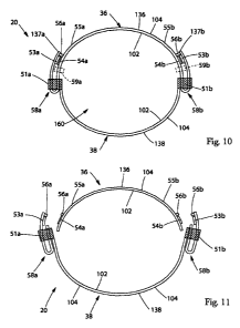
OVERLAP SEAM PROGRESSION FIGURES
In one embodiment, referring to Figs. 9-13, 18, and 22, the absorbent article
10 may be
folded about a lateral axis 44 to form a pant 20 comprising overlap seams 58.
The absorbent
article 10 may comprise a front waist region 36 comprising a front waist end
edge 136, a back
waist region 38 comprising a back waist end edge 138, one or more first
fastening components
53, one or more second fastening components 54, one or more non-engagement
zones 54,
optionally, one or more closure bonds 56, and a longitudinal axis 42. In one
embodiment, the
one or more closure bonds 56 may not be present until the absorbent article 10
is folded about the
lateral axis 44 and readied to be formed into the pant 20. In various
embodiments, the absorbent
article 10 may comprise one or more first fastening components 53 disposed in
a first waist
region and may optionally comprise one or more second fastening components 55
disposed in the
same waist region as the first fastening components 53. The one or more second
fastening
components 55 may be formed as a portion of the first waist region, formed
integral with a
portion of the first waist region, or attached to or disposed on a portion of
the first waist region.
In one embodiment, more than two second fastening components 55 may be
provided along an
area of the first waist region, for example. In various embodiments, the first
fastening
components 53 and the second fastening components 55 may be disposed in the
same waist
region (e.g., the first waist region 36) and on the same surface of the same
waist region 36 (e.g.,
the exterior surface 104).
CA 02787511 2012-07-18
WO 2011/091110 PCT/US2011/021820
Now described is the progression of how the absorbent article 10 may be formed
into the
pant 20 (i.e., steps taken by the manufacturer). In one embodiment, referring
to Fig. 9, a
simplified version of the absorbent article 10 is illustrated. While the
absorbent article 10 is
illustrated as being comprised of a single panel, those of skill in the art
will recognize that the
5 absorbent article 10 may be comprised of multiple panels or components, such
as topsheets,
backsheets, containment regions, absorbent cores, leg cuffs, waistbands,
elastics, and/or side
panels, for example. The simplified version is illustrated merely for
simplicity in the explanation
of the progression of formation. To form the pant 20, first, the absorbent
article 10 is folded
about the lateral axis 44 such that the interior surface 102 of the front
waist region 36 is brought
10 into a surface-to-surface facing position with the interior surface 102 of
the back waist region 38.
In one embodiment, this configuration is illustrated in Fig 10. As can be
seen, a permanent side
seam 51 may be formed to create an overlap seam. The overlap permanent side
edge seam 51
may be created by bringing a portion of the interior surface 102 of the front
waist region 36 into a
surface-to-surface orientation with a portion of the exterior surface 104 of
the back waist region
15 38 as shown in Fig. 10. Alternatively, the overlap permanent side edge seam
51 may be created
by bringing a portion of the exterior surface 104 of the front waist region 36
into a surface-to-
surface orientation with a portion of the interior surface 102 of the back
waist region 38 as shown
in Fig. 18 (see also Figs. 1 and 2). In other embodiments, the overlap
permanent side edge seam
51 may be created by bringing a portion of the interior surface 102 of the
front waist region 36
20 into a surface-to-surface orientation with a portion of the interior
surface 102 of the back waist
region 38 as shown in Fig. 22. In one embodiment, the bond used to form the
permanent side
seam 51 may be formed by various methods, such as adhesive bonding, permanent
cohesive
bonding, thermal bonding, ultrasonic bonding or pressure bonding, for example.
While in the
configuration of Fig. 10, the front waist region 36 is joined to the back
waist region 38 via the
25 overlap seams 58. A separation zone 59 may be formed between each first
fastening component
53 and each permanent side edge seam 51 in the front waist region 36.
Optionally, in the step
illustrated in Fig. 10, one or more closure bonds 56 may be formed by various
methods, such as
adhesive bonding, cohesive bonding, thermal bonding, ultrasonic bonding or
pressure bonding,
for example. The closure bond 56 may be disposed on the exterior surface 104
of the front waist
region 36 at or adjacent each side edge 137 and/or each first fastening
component 53. Next, still
referring to Fig. 10, the portions of the absorbent article 10 comprising the
overlap seams 58
and/or the first fastening components 53 can be folded laterally inward, in a
direction toward the
longitudinal axis 42. In one embodiment, the closure bonds 56 may hold the
folded over portion
CA 02787511 2012-07-18
WO 2011/091110 PCT/US2011/021820
26
against the exterior surface 104 of the front waist region 36 of the pant 20.
In one embodiment,
the fully formed pant 20 is illustrated in Fig. 10. As can be seen in Fig. 10,
the fully formed pant
20 comprises an initial waist opening circumference 160. In such an
embodiment, the first
fastening components 53 are not used to maintain or form the initial waist
opening circumference
160 and, in fact, are not fastenably engaged with the second fastening
components 55 or other
portions of the pant 20 although they may be in surface-to-surface contact
with the non-
engagement zones 54. As discussed herein, the non-engagement zones 54 prevent,
or at least
inhibit, the first fastening components 53 from fastening with a portion of
the pant 20 when
packaged. In certain instances, the consumer (e.g., caregiver) would receive
the pant 20 in the
configuration illustrated in Fig. 10.
In one embodiment, the caregiver, upon receipt of the pant 20 or removal of
the pant 20
from a package (the pant 20, in one embodiment, being in the configuration
illustrated in Fig.
10), may decide to apply the pant 20 as a pull-on training pant or as a type-
style diaper. To apply
the pant 20 as a pull-on training pant, the caregiver may use the pant 20 like
underwear and have
the wearer place one foot in each leg openings and pull the pant 20 up to an
area about the
wearer's waist. In this configuration, the first fastening components 53 would
not be fastenably
engaged with a portion of the pant 20 or with the second fastening components
55. Instead, the
overlap seam 58 would maintain the initial waist opening circumference 160
around the wearer's
waist. If the caregiver needs to check the pant 20 at any time during use by
the wearer, the
caregiver can pull on a portion of the pant adjacent the side edge 137 to
separate or break the
closure bond 56 and then rotate the folded over portion away from the
longitudinal axis 42
thereby separating or tearing the separation zone 59. In one embodiment, the
separated or torn
separation zones 59 are illustrated in Fig. 11. In various embodiments, one or
more portions of
the front waist region 36 that have been separated from the remainder, central
portion, of the
front waist region 36 may then be reattached to the front waist region 36,
similar to the example
configuration illustrated in Figs. 12 and 13. When the pant 20 is in the
configurations of Figs. 11
and 12, the caregiver can check the pant 20 to determine if a pant change
needs to be made. If a
pant change does not need to be made, the caregiver can refasten the pant 20
by engaging the
first fastening components 53 and the second fastening components 55 with each
other to create a
second waist opening circumference 61. One embodiment of such engagement is
illustrated in
Fig. 13. In embodiments, where the separate second fastening components 55 are
not provided,
the caregiver may engage the first fastening components 53 with another
portion of the front
waist region 36 (e.g., the backsheet 83) forming the second fastening
component 55.
CA 02787511 2012-07-18
WO 2011/091110 PCT/US2011/021820
27
In one embodiment, to apply the pant 20 as a type-style diaper, the caregiver
can pull on a
portion of the pant adjacent the side edge 137 to separate or break the
closure bond 56 and rotate
the folded over portion away from the longitudinal axis 42 thereby separating
or tearing the
separation zone 59. In one embodiment, this configuration is illustrated in
Fig. 11. Referring to
Fig. 12, the pant 20 may then be unfolded about the lateral axis 44. When the
pant 20 is
unfolded, in one embodiment, referring to Fig. 12, one or more portions of the
front waist region
36 may remain attached to the back waist region 38. In this configuration the
pant 20 can be
applied to the wearer like a tape-style diaper. In one embodiment, the applied
configuration is
illustrated in Fig. 13. In Fig. 13, the first fastening components 53 are
engaged with the second
fastening components 55 or other portions of the front waist region 36 to
create a second waist
opening circumference 61.
EXAMPLE EMBODIMENTS
In one embodiment, referring to Figs. 14-17, the laterally opposing permanent
side seams
51 may be disposed at or adjacent the side edges 137 in one or both waist
regions 36 and/or 38.
In embodiments wherein the lateral extent of the front waist region 36 is
substantially equal to
the lateral extent of the back waist region 38 during bonding of the permanent
side edge seams
51, the permanent side edge seams 51 may be disposed at or adjacent the side
edges 137 of the
absorbent article 10 in both the front and back waist regions 36 and 38. In
one embodiment, the
absorbent article 10 is folded at a laterally extending fold line disposed in
the crotch region 37 to
bring the front waist region 36 and the back waist region 38 into an interior
surface to interior
surface, face to face orientation. The permanent side edge seams 51 may be
formed by placing
the interior surface 102 of one of the waist regions 36 or 38 in an
overlapping relationship with
the exterior surface 104 of the opposing waist region 36 or 38 adjacent the
side edges 137 and
subsequently bonding the waist regions 36 and 38 together. The first fastening
component 53
may be applied to the absorbent article 10 prior to forming the permanent side
edge seam 51.
The second fastening component 55 may also be applied prior to forming the
permanent side
edge seam 51 or after forming the permanent side edge seam 51. In this
embodiment, the first
fastening component 53 and/or the non-engagement zone 54 may be disposed at
least partially
within the permanent side edge seam 51 with the fastening surface of the first
fastening
component 53 in a face to face surface to surface orientation with the non-
engagement zone 54.
When removed from the package, the absorbent article 10 is in the form of the
pant 20. The
caregiver may apply the absorbent article 10 to the wearer as a pant or as a
tape-style diaper by
CA 02787511 2012-07-18
WO 2011/091110 PCT/US2011/021820
28
first releasing the first fastening component 53 by separating the front waist
region 36 from the
back waist region 38 by breaking the permanent side edge seam 51 thereby
opening the initial
waist opening circumference 160 (the closure bond 56 if present may also be
broken, for
example), then placing the back waist region 38 of the absorbent article 10
under the wearer and
fastening the first fastening component 53 to the second fastening component
55, another portion
of the front waist region 36, or another portion of the absorbent article 10
to re-close the pant 20
on the wearer. In one embodiment, Fig. 15A is a cross-sectional view of the
absorbent article 10
of Fig. 14, taken along line A-A. In one embodiment, Fig. 15B is a cross-
sectional view of the
absorbent article 10 of Fig. 14, taken along line B-B. In one embodiment, Fig.
16 is a
perspective view of the pant 20 formed with an overlap seam. In various
embodiments, Fig. 16
may comprise various indicia or graphics 76 to indicate to a caregiver where
to land or fasten the
first fastening component 53 to create the second waist opening circumference.
In one
embodiment, the indicia or graphics 76 may be shaped to illustrate various
waist circumferences,
for example. In one embodiment, Fig. 17 is a cross-sectional view of the pant
20 of Fig. 16,
taken along line D-D.
In one embodiment, referring to Figs. 18 and 19, the laterally opposing
permanent side
seams 51 may be disposed at or adjacent the side edges 137 in one or both
waist regions 36
and/or 38. In embodiments where the lateral extent of one of the front or back
waist regions 36
or 38 is greater than the lateral extent of the opposing waist region 36 or 38
at the point of
bonding the permanent side edge seams 51, the permanent side edge seams 51 may
be disposed
at or adjacent the side edge 137 of the absorbent article 10 in one waist
region 36 or 38 and
disposed laterally inward of the side edge 137 in the opposing waist region 36
or 38. In one
embodiment, the absorbent article 10 is folded at a laterally extending fold
line disposed in the
crotch region 37 to bring the front waist region 36 and the back waist region
38 into an interior
surface to interior surface, face to face orientation. The permanent side edge
seams 51 may be
formed by placing the interior surface 102 of one waist regions 36 or 38 in an
overlapping
relationship with the exterior surface 104 of the opposing waist region 36 or
38 adjacent the side
edges 137 and subsequently bonding the waist regions 36 and 38 together. The
first fastening
component 53 may be applied to the absorbent article 10 prior to forming the
permanent side
edge seam 51. The second fastening component 55 may also be applied prior to
forming the
permanent side edge seam 51 or after forming the permanent side edge seam 51.
In this
embodiment, the first fastening component 53 and the non-engagement zone 54
may be disposed
adjacent the permanent side edge seam 51 with the fastening surface of the
first fastening
CA 02787511 2012-07-18
WO 2011/091110 PCT/US2011/021820
29
component 53 in a face to face, surface to surface orientation with the non-
engagement zone 54.
When removed from the package, the absorbent article 10 is in the form of the
pant 20. The
caregiver may apply the pant 20 to the wearer as a pant or as a tape-style
diaper by first breaking
the initial waist opening circumference 160, releasing the first fastening
component (by breaking
the closure bond 56 if present, for example), placing the back waist region 38
of the absorbent
article 10 under the wearer and fastening the first fastening component 53 to
the second fastening
component 53, to a portion of the front waist region 36, or to another portion
of the absorbent
article 10 to re-close the pant 10 about the waist of the wearer to form a
second waist opening
circumference. In one embodiment, Fig. 19 is illustrated with both separation
zones 59 separated
and a first side in the unattached configuration and a second side in the
reattached configuration.
In one embodiment, referring to Figs. 20 and 21, the lateral extent of the
absorbent article
10 in one of the waist regions 36 or 38 is greater than the lateral extent of
the absorbent article 10
in the opposing waist region 36 or 38 prior to bonding of the permanent side
edge seams 51, the
permanent side edge seam 137 may be disposed at or adjacent the side edge 137
of the one of the
waist regions 36 or 38 and be disposed laterally outward from the side edge
137 of the opposing
waist region 36 or 38. In one embodiment, the absorbent article 10 may be
folded at a laterally
extending fold line disposed in the crotch region 37 to bring the front waist
region 36 and the
back waist region 38 into an interior surface to interior surface, face to
face orientation. In
certain embodiments, a portion of the chassis 100 comprising the first
fastening component 53
may be folded laterally inward thereby positioning the fastening surface of
the first fastening
component 53 in a face to face, surface to surface orientation with a non-
engagement zone 54.
The laterally inward folded portion of the chassis 100 comprising the first
fastening component
53 and/or the permanent side edge seam 51 is releasably attached to the
exterior surface 104 of
the absorbent article 10 to maintain the position of the first fastening
component 53 until it is
released by the caregiver (by breaking the closure bond 56, for example).
Subsequently, the
permanent side edge seams 51 may be formed by bonding the interior surface 102
of one waist
regions 36 or 38 to the exterior surface 104 of the opposing waist region 36
or 38. The first
fastening component 53 may be applied to the absorbent article 10 prior to
forming the
permanent side edge seam 51. The second fastening component 55 may also be
applied prior to
forming the permanent side edge seam 51 or after forming the permanent side
edge seam 51.
When removed from the package, the absorbent article 10 is in the form of the
pant 20. The
caregiver may apply the pant 20 to the wearer as a pant or alternatively the
caregiver may apply
the absorbent article 10 as a tape-style diaper by first unfolding the
laterally inwardly folded
CA 02787511 2012-07-18
WO 2011/091110 PCT/US2011/021820
portion of the chassis 100 (breaking the closure bond 56, for example),
breaking the initial waist
opening circumference 160, placing the back waist region 38 of the absorbent
article 10 under the
wearer and fastening the first fastening component 53 to the optional second
fastening
component 55, to a portion of the front waist region 36, or to another portion
of the absorbent
5 article 10, thereby re-closing the pant 20 about the waist of the wearer to
form a second waist
opening circumference. In one embodiment, Fig. 21 is illustrated with both
separation zones 59
separated and a first side in the unattached configuration and a second side
in the reattached
configuration.
In one embodiment, referring to Fig. 22 and 23, the lateral extent of the
absorbent article
10 10 in one of the waist regions 36 or 38 is greater than the lateral extent
of the absorbent article 10
in the opposing waist region 36 or 38 prior to bonding of the permanent side
edge seams 51, the
permanent side edge seams 51 may be disposed at or adjacent the side edge 137
of the one of the
waist regions 36 or 38 and be disposed laterally outward from the side edge
137 of the opposing
waist region 36 or 38. In one embodiment, the absorbent article 10 may be
folded at a laterally
15 extending fold line disposed in the crotch region 37 to bring the front
waist region 36 and the
back waist region 38 into an interior surface to interior surface, face to
face orientation. In
certain embodiments, the portion of the chassis 100 comprising the first
fastening component 53
may be folded laterally inward thereby positioning the fastening surface of
the first fastening
component 53 in a face to face, surface to surface orientation with a non-
engagement zone 54.
20 The laterally inward folded portion of the chassis 100 comprising the first
fastening component
53 is releasably attached to the exterior surface 104 of the absorbent article
10 to maintain the
position of the first fastening component 53 until it is released by the
caregiver (by breaking the
closure bond 56, for example). Subsequently, the permanent side edge seams 51
are formed by
bonding the interior surface 102 of one waist regions 36 or 38 to the interior
surface 102 of the
25 opposing waist region 36 or 38. The first fastening component 53 may be
applied to the
absorbent article 10 prior to forming the permanent side edge seam 51. The
second fastening
component 55 may also be applied prior to forming the permanent side edge seam
51 or after
forming the permanent side edge seam 51. When removed from the package, the
absorbent
article 10 is in the form of the pant 20. The caregiver may apply the
absorbent article 10 to the
30 wearer as a pant or as a tape-style diaper by unfolding the laterally
inwardly folded portion of the
chassis 100 (by breaking the closure bond 56, for example), breaking the
initial waist opening
circumference 160, placing the back waist region 38 of the absorbent article
10 under the wearer
and fastening the first fastening component 53 to the second fastening
component 55, a portion of
CA 02787511 2012-07-18
31
the front waist region 36, or a portion of the absorbent article 10 thereby re-
closing the pant 20
about the waist of the wearer to form a second waist opening circumference. In
one embodiment,
Fig. 23 is illustrated with both separation zones 59 separated and a first
side in the unattached
configuration and a second side in the reattached configuration.
PCT International Publication No. W02011/091117, filed on January 20, 2011,
naming Gary
Dean LaVon as an inventor, generally discloses various acceptable product
features that may be
implemented in the embodiments described in the present application.
Specifically, the above-
described embodiments may, as appropriate, comprise a fastening system and
side panels.
METHOD OF MAKING
The following method of making description refers generally to Figs. 24-28c.
Like
element
references from above will apply below even if they are not illustrated in
Figs. 24-28c. Some
numbering from above may also overlap with numbering from below.
In one embodiment, a method of forming an absorbent article 10 in the form of
a
prefastened pant incorporates the use of an apparatus that reconfigures the
absorbent article 10
from an open partially assembled, unfastened configuration to a pre-fastened
configuration
during the manufacturing thereof.
In one embodiment, the apparatus comprises a plurality of folding devices 230
disposed
on a transport device which is configured in the form of a wheel or drum as
shown in Figs 24 and
25. During the manufacture of prefastened pants 20, the folding device 230
receives a discrete
absorbent article 10 in a flat, open, unfastened, configuration. The discrete
absorbent article 10 is
held in place on folding arms 60 and 63. The folding device 230 is adapted to
fold the discrete
absorbent article 10 from its flat open configuration to a bifold
configuration, to form pant 20,
wherein the absorbent article 10 is folded about the lateral axis 44 disposed
in the crotch region
37, folding a first waist region of the absorbent article 10 in a direction
generally toward the
opposing waist region as shown in Fig. 26. In addition to folding the
absorbent article 10 about
the lateral axis 44, the folding device 230 can also fold one or more portions
of the absorbent
article 10, for example portions of the side panels 189, disposed adjacent the
longitudinally
extending side edges 137 laterally inward such that a portion disposed in a
first waist region is
placed in an overlapping face-to-face orientation with a portion of the
absorbent article 10 in the
opposing waist region as shown in Fig. 27 to form an overlapping permanent
side edge seam 51.
CA 02787511 2012-07-18
WO 2011/091110 PCT/US2011/021820
32
When refastenable fastening elements are disposed at or adjacent the
longitudinally extending
side edges 137 in one or both of the waist regions 36 and 38, the folding
device 230 may fold the
portion of the absorbent article 10 comprising a first fastening component 53
toward the
opposing waist region placing the portion of the absorbent article 10
comprising the first
fastening component 53 in a face-to-face, surface-to-surface relationship with
a portion of the
chassis 100 in the opposing waist region. The folding device 230 may encourage
the portions of
the first waist region and the portions of the second waist region into
contact to form a permanent
side edge seam 51, examples of such permanent side edge seams are shown in
Figs. 28a-c. The
permanent side edge seam 51 may comprise an adhesive bond, a cohesive bond, a
thermal bond,
ultrasonic bond, a pressure bond or any suitable bonding methods or devices.
The folding device
230 and/or the transport device 210 may comprise a retention device intended
to maintain the
position of the absorbent article 10 on the transport device 210 until the
absorbent article 10 is
removed for further processing. U.S. Pat. Publ. No. 2008/0083489 and U.S. Pat.
No. 5,779,831
generally disclose various acceptable embodiments for carrying out the process
as described
above and as described in the present application's Figs. 24-28c. More
specifically, the transport
device (processing wheel), folding device (processing station), side panel
folding and seaming
devices (gripper and sealer) as disclosed in U.S. Pat. Publ. No. 2008/0083489
and U.S. Pat. No.
5,779,831 may be used in the process of the present application.
In one embodiment of the method of making, a continuous web comprising a
plurality of
interconnected backsheets 83 is combined with a series of laterally opposing
pairs of discrete side
panels 189. The side panels 189 may comprise a material that is elastically
extensible and may
additionally comprise a refastenable fastening component disposed on a surface
of the side panel
189. The continuous web of interconnected backsheets 83 is subsequently joined
with a
continuous web comprising a plurality of interconnected topsheets 81. Discrete
absorbent cores
200 are disposed between the continuous backsheet 83 web and the continuous
topsheet 81 web
thereby forming a plurality of interconnected absorbent containment
assemblies. The web is
severed to form a plurality of discrete absorbent articles 10. The discrete
absorbent articles 10
are disposed in an unfolded and unfastened state, i.e., the first fastening
component 53 and
second fastening component 55 are unfastened. The discrete absorbent article
10 is transported in
a machine direction and folded longitudinally about the lateral axis 44
disposed in the crotch
region 37 such that the front waist region 36 and the back waist region 38 are
disposed in an
internal surface 102 to internal surface 102, face-to-face relationship. A
portion of the absorbent
article 10 comprising a first fastening component 53 in a first waist region
is folded laterally
CA 02787511 2012-07-18
WO 2011/091110 PCT/US2011/021820
33
inward toward the second waist region and a portion of the absorbent article
10 comprising a
non-engagement zone 54 disposed in the second waist region is folded laterally
inward toward
the first waist region. The laterally folded portions of the absorbent article
10 comprising the
first fastening component 53 is disposed in an overlapping, face-to-face
relationship with the
portion of the absorbent article 10 comprising the non-engagement zone 54. In
such an
embodiment, the fastening surface of the first fastening component 53 is
brought into surface-to-
surface contact with the non-engagement surface of the non-engagement zone 54.
The
overlapping region may be subsequently bonded to form a permanent side edge
seam 51. The
side edge seam 51 may be formed by a thermal bond, ultrasonic bond, a pressure
bond or other
suitable bonding methods or devices. A portion of one or both of the first
fastening component
53 and non-engagement zone 54 may be disposed within the permanent side edge
seam 51.
In an alternative embodiment of the method of making, a continuous web
comprising a
plurality of interconnected backsheets 83 is combined with a series of
laterally opposing pairs of
discrete side panels 189. The side panels 189 may comprise a material that is
elastically
extensible and may additionally comprise a refastenable fastening component
disposed on a
surface of a side panel 189. The side panel 189 may comprise a non-engagement
zone 54
disposed on or forming a portion of the surface of the side panel 189. A
portion of the side panel
189 comprising a first fastening component 53 may be folded laterally inward
to position the first
fastening component 53 in a face-to-face, surface-to-surface orientation with
the non-engagement
zone 54. The attachment of the first fastening component 53 to the side panel
189 as well as the
folding of the side panel 189 may take place either before or after attaching
the side panel 189 to
the continuous web of interconnected backsheets 83. The continuous web of
interconnected
backsheets 83 is subsequently joined with a continuous web comprising a
plurality of
interconnected topsheets 81. Discrete absorbent cores 200 are disposed between
the continuous
backsheet 83 web and the continuous topsheet 81 web thereby forming a
plurality of
interconnected absorbent containment assemblies. The web is severed to form a
plurality of
discrete absorbent articles 10. The discrete absorbent articles 10 are
disposed in an unfolded and
unfastened state, i.e. the first fastening component 53 and second fastening
component 55 are
unfastened. The discrete absorbent article 10 is transported in a machine
direction and folded
longitudinally about the lateral axis 44 disposed in the crotch region 37 such
that the first waist
region and the second waist region are disposed in an internal surface 102 to
internal surface 102,
face-to-face relationship. A portion of the absorbent article 10 comprising a
first fastening
component 53 in a first waist region is folded laterally inward toward the
second waist region and
CA 02787511 2012-07-18
WO 2011/091110 PCT/US2011/021820
34
a portion of the absorbent article 10 comprising a non-engagement zone 54
disposed in the
second waist region is folded laterally inward toward the first waist region.
The laterally folded
portions of the absorbent article 10 in a first waist region comprising the
first fastening
component 53 is disposed in an overlapping, face-to-face relationship with a
portion of the
absorbent article 10 disposed in the opposing waist region. The overlapping
region may be
subsequently bonded to form a permanent side edge seam 51. The permanent side
edge seam 51
may be formed by an adhesive bond, cohesive bond, thermal bond, ultrasonic
bond, a pressure
bond or other suitable bonding methods or devices. A portion of one or both of
the first fastening
component 53 and non-engagement zone 54 may be disposed within the permanent
side edge
seam 51.
In one embodiment of the method of making, a continuous web comprising a
plurality of
interconnected backsheets 83 is combined with a series of laterally opposing
pairs of discrete side
panels 189. The side panels 189 may comprise a material that is elastically
extensible and may
additionally comprise a refastenable fastening component disposed on a surface
of the side panel
189. The side panel 189 may comprise a non-engagement zone 54 disposed on or
forming a
portion of the surface of the side panel 189. The attachment of the first
fastening component 53
and creation of the non-engagement zone 54 may take place either before or
after attaching the
side panel 189 to the continuous web of interconnected backsheets 83. The
continuous web of
interconnected backsheets 83 is subsequently joined with a continuous web
comprising a
plurality of interconnected topsheets 81. Discrete absorbent cores 200 are
disposed between the
continuous backsheet 83 web and the continuous topsheet 81 web thereby forming
a plurality of
interconnected absorbent containment assemblies. The web is severed to form a
plurality of
discrete absorbent articles 10. The discrete absorbent articles 10 are
disposed in an unfolded and
unfastened state, i.e. the first fastening component 53 and second fastening
component 55 are
unfastened. The discrete absorbent article 10 is transported in a machine
direction and folded
longitudinally about the laterally extending axis 44 disposed in the crotch
region 37 such that the
first waist region and the second waist region are disposed in an internal
surface 102 to internal
surface 102, face-to-face relationship. A portion of the absorbent article 10
comprising a first
fastening component 53 in a first waist region is folded laterally inward
toward the second waist
region and a portion of the absorbent article 10 comprising a non-engagement
zone 54 disposed
in the second waist region is folded laterally inward toward the first waist
region. The laterally
folded portions of the absorbent article 10 in a first waist region comprising
the first fastening
component 53 are disposed in an overlapping face-to-face relationship with a
portion of the
CA 02787511 2012-07-18
absorbent article 10 disposed in the opposing waist region. The overlapping
region may be
subsequently bonded to form a permanent side edge seam 51. The side edge seam
51 may be
formed by an adhesive bond, cohesive bond, thermal bond, ultrasonic bond, a
pressure bond or
other suitable bonding methods or devices. A portion of the side panel 189
comprising the first
5 fastening component 53 may be folded laterally inward to position the first
fastening component
53 in a face-to-face, surface-to-surface orientation with the non-engagement
zone 54. A portion
of one or both of the first fastening component 53 and non-engagement zone 54
may be disposed
laterally inward of the permanent side edge seam 51.
The dimensions and values disclosed herein are not to be understood as being
strictly
10 limited to the exact numerical values recited. Instead, unless otherwise
specified, each such
dimension is intended to mean both the recited value and a functionally
equivalent range
surrounding that value. For example, a dimension disclosed as "40 mm" is
intended to mean
"about 40 mm".
All documents cited in the Detailed Description are not to be construed as an
admission
15 that they are prior art with respect to the present disclosure. To the
extent that any meaning or
definition of a term in the present disclosure conflicts with any meaning or
definition of the term
in a document cited herein, the meaning or definition assigned to the term in
the present
disclosure document shall govern.
The citation of any document, including any cross referenced or related patent
or
20 application, is not an admission that it is prior art with respect to any
invention disclosed or
claimed herein or that it alone, or in any combination with any other
reference or references,
teaches, suggests or discloses any such invention. Further, to the extent that
any meaning or
definition of a term in this document conflicts with any meaning or definition
of the same term in
a document cited herein, the meaning or definition assigned to that term in
this document shall
25 govern.
While particular embodiments of the present invention have been illustrated
and
described, it would be obvious to those skilled in the art that various other
changes and
modifications can be made without departing from the invention described
herein.