Note: Descriptions are shown in the official language in which they were submitted.
CA 02787703 2012-07-20
WO 2011/088575 PCT/CA2011/050031
1
TITLE OF THE INVENTION
MESH LIGHTING SYSTEM FOR EMERGENCY VEHICLES
FIELD OF THE INVENTION
[0001] The present invention relates to a mesh lighting system for
emergency vehicles. In particular, the present invention relates to portable
wireless lighting system suitable for retrofit in a conventional vehicle such
as a
rental car without requiring modifications to the vehicle.
BACKGROUND OF THE INVENTION
[0002] Emergency vehicles such as police cars, ambulances and the like
are typically equipped with visual signalling such as flashing lights and
strobes,
to indicate their presence to other road users. Such flashing lights and
strobes
are typically hardwired into the electrical system of the vehicle in question.
Other such lights may be retrofit by attaching a light unit to the automobile
and
taking advantage, for example, of an appropriate adapter inserted into the
lighter outlet.
[0003] One drawback of such systems is that they typically require
modification to the vehicles electrical system. This provides difficulties,
for
example, when security or emergency personnel are operating in regions
where the vehicles must be temporarily leased and where modification of the
vehicle in question proves an unsuitable alternative. Additionally, existing
retrofit units typically comprise a control/power unit and one or more
lighting
units interconnected using wires. Such retrofit units are cumbersome and
difficult to employ on a large variety of vehicles given the difference in
distances between the control/power unit and the light sources. Also, as the
control/power unit is within the automobile and the light sources typically on
the
outside of the vehicle, a cable must pass through an open window or doorjamb
CA 02787703 2012-07-20
WO 2011/088575 PCT/CA2011/050031
2
which leads to a substandard implementation.
[0004] Another drawback is that prior art retrofit systems typically include
a large light bar which is cumbersome, not readily portable and difficult to
attach to many vehicles which might otherwise be used by emergency
personnel.
[0005] What is needed therefore, and an object of the present invention,
is a lighting system for emergency vehicles comprising a variety of signalling
light sources synchronised using a wireless communication system.
SUMMARY OF THE INVENTION
[0006] In order to address the drawbacks of the prior art, there is
provided a mesh lighting system for emergency vehicles. The system
comprises a plurality of independent signalling light sources each supplied by
a
dedicated source of energy, a control module, a low powered wireless network
connecting the control module with the plurality of light sources, wherein the
plurality of independent signalling light sources emit at least one light
flash in
response to a control signal received from the control module.
[0007] There is also disclosed a method for retrofitting a vehicle with an
emergency lighting system. The method comprises providing a plurality of
independent signalling light sources each supplied by a dedicated source of
energy and placing the light sources about the vehicle so they are visible
from
a vehicle exterior, each independent signalling light sources comprising a
fastener for fastening to the vehicle, and interconnecting each of the
independent signalling light sources with a control module using a low powered
wireless network. Each of the plurality of independent signalling light
sources
emits at least one light flash in response to a control signal received from
the
control module via the low powered wireless network.
CA 02787703 2012-07-20
WO 2011/088575 PCT/CA2011/050031
3
[0008] Additionally, there is disclosed a portable kit lighting system for
emergency vehicles. The kit comprises a plurality of independent signalling
light sources each comprising a dedicated standardised battery, a control
module, a sound emitting source, a plurality of replacement batteries, an
instruction manual, and a rugged sealable plastic box comprising a foam liner
comprising a series of cut-outs configured, one of each of the cut-outs for
receiving a respective one of the plurality of independent signalling light
sources, the control module, the sound emitting source and the plurality of
replacement batteries.
[0009] Other objects, advantages and features of the present invention
will become more apparent upon reading of the following non-restrictive
description of specific embodiments thereof, given by way of example only with
reference to the accompanying drawings.
BRIEF DESCRIPTION OF THE DRAWINGS
[0010] Figure 1 is a schematic diagram of a mesh lighting system in
accordance with an illustrative embodiment of the present invention;
[0011] Figure 2 is a schematic diagram of a control unit for use in a
mesh lighting system in accordance with an illustrative embodiment of the
present invention;
[0012] Figure 3 is a schematic diagram of a light source for use in a
mesh lighting system in accordance with an illustrative embodiment of the
present invention;
[0013] Figure 4A is a front raised perspective view of a mesh lighting
system mounted on a vehicle in accordance with an illustrative embodiment of
the present invention;
CA 02787703 2012-07-20
WO 2011/088575 PCT/CA2011/050031
4
[0014] Figure 4B is a left rear raised perspective view of a mesh lighting
system mo7unted on a vehicle in accordance with an illustrative embodiment of
the present invention;
[0015] Figure 4C is a left side view of a light source mounted to a vehicle
using a magnet and clip in accordance with an illustrative embodiment of the
present invention;
[0016] Figure 4D is a left side view of a light source mounted to a
window on the inside of a vehicle using an adhesive shroud in accordance with
an illustrative embodiment of the present invention;
[0017] Figure 4E is a left side view of a light source mounted to a visor
behind the windscreen on the inside of a vehicle using a clip in accordance
with
an illustrative embodiment of the present invention;
[0018] Figure 5 is a schematic diagram of the electronics of a horn
module in accordance with an illustrative embodiment of the present invention;
and
[0019] Figure 6 is a raised front view of a kit comprising a mesh lighting
system and instructions for operation in accordance with an illustrative
embodiment of the present invention.
DETAILED DESCRIPTION OF THE ILLUSTRATIVE EMBODIMENTS
[0020] Referring now to Figure 1, and in accordance with an illustrative
embodiment of the present invention, a mesh lighting system, generally
referred to using the reference numeral 10, will now be described. The mesh
lighting system is illustratively comprised of a control unit 12 and a
plurality of
small portable self powered light sources 14 interconnected using wireless
CA 02787703 2012-07-20
WO 2011/088575 PCT/CA2011/050031
communication links as in 16 for the transfer of control signals.
[0021] Still referring to Figure 1, although the present illustrative
embodiment discloses a distinct control unit 12 for powering the plurality of
light
5 sources 14, in an alternative embodiment one of the light sources 14 would
act
as a master and provide the requisite control with the remaining light sources
as in 14 slaved to the master.
[0022] Referring to Figure 2, the control unit 12 is illustratively
microprocessor controlled and comprises a Central Processing Unit (CPU) 18
and supportive memory (Read Only Memory, ROM, 20, and Random Access
Memory, RAM, 22). The ROM 20 has typically stored therein basic operating
software, default settings and the like. RAM 22, which can be in the form of
non-volatile static RAM or flashable EEPROM or the like, allows for the
provision of software updates, user settings, and the like. The RAM 22 can be
included on board the control unit 12 or introduced via a flash card interface
(not shown), for example through provision of a suitable Micro SD interface or
the like. Alternatively a USB interface could be provided (also not shown) and
additional RAM 22 provided using a memory stick or the like. The controller
also includes a User Interface 24, such as a keypad and display, touch screen,
or other suitable interface means for allowing the user to input requisite
control
and configuration information and receive information regarding device status,
battery power and the like. Additionally, an Input/Output, I/O, transceiver 28
and antennae 30 is provided for interconnecting the control unit 12 with the
plurality of light sources (references 14 in Figure 1) in order to provide the
requisite control signals. The transceiver 28 is preferably limited to a
secure
short range operation, for example using BluetoothTM, Zigbee or the like, or
could be provided via for example via a low power wireless ad hoc network.
[0023] Still referring to Figure 2, in a particular embodiment the I/O
transceiver 28 can also provide an interface for updating the ROM 20 and RAM
22, for example in the case of software updates and the like, and function as
a
CA 02787703 2012-07-20
WO 2011/088575 PCT/CA2011/050031
6
means for interconnecting a portion of the user interface 24 with the CPU 18
(for example, through provision of a BluetoothTM transceiver and BluetoothTM
compatible input and output devices).
[0024] Still referring to Figure 2, a power source 32 is illustratively also
provided for powering the control unit 12, for example a battery or the like.
In a
particular embodiment power could also be provided through an external
means such as an appropriate adaptor for insertion into the in-car cigarette
lighter socket (both not shown).
[0025] In an illustrative embodiment the control unit 12 is in the form of a
key fob or the like and wherein the user interface 24 comprises one or more
buttons (not shown) for controlling the operation light sources as in 14. In a
particular embodiment, the control unit would comprise four (4) buttons, for
example for turning the system on and off, for illuminating the various
independent light sources as in 14 as well as, as will be seen below,
controlling
emission of sounds from the sound emitting source. Illustratively,
combinations
of buttons could be used to place the mesh lighting system 10 in different
modes.
[0026] Referring to Figure 3, similar to the control unit 12, each of the
plurality of light sources 14 illustratively is microprocessor controlled and
comprises a Central Processing Unit (CPU) 34 and supportive ROM 36 and
RAM 38. Again, the ROM 36 has typically stored therein basic operating
software, default settings and the like. RAM 38, which can be in the form of
non-volatile static RAM or flashable EEPROM or the like, allows for the
provision of software updates, user settings, and the like. The RAM 38 can be
included on board the light source 14 or introduced via a flash card interface
(not shown), for example through provision of a suitable Micro SD interface or
the like.
[0027] Still referring to Figure 3, the light source 14 further comprises an
CA 02787703 2012-07-20
WO 2011/088575 PCT/CA2011/050031
7
Input/Output, or I/O, transceiver 40 and antenna 42 for communication with the
control unit 12 and via which the control unit 12 provides control signals.
The
control signals are used by the CPU 34 in combination with an LED driver 44 to
selectively illuminate one or more LEDs as in 46. Illustratively, the LEDs 46
are
driven by the CPU 34 and driver 44 to illuminate, for example, in one of a
variety of colours, intensities, periodicity and the like, each of which may
be
dictated by the control signals received from the control unit 12. A typical
illumination for police operations, for example, would comprise a combination
of
red and blue LEDs operating with a strobe effect.
[0028] Still referring to Figure 3, the light source 14 further comprises a
user interface 48, typically comprising at least an on/off switch but
additionally
could further comprise a means for introducing user configuration information,
for example by selecting a particular signalling mode or the like. Similar to
the
control unit, the user interface 48 could be provided in part via the I/O
transceiver 40, for example through provision of a BluetoothTM compatible
interface and one or more BluetoothTM compatible user input devices (not
shown).
[0029] Still referring to Figure 3, a local source of power 50 is also
provided, for example a battery or the like.
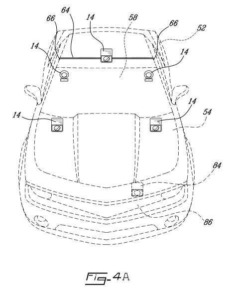
[0030] Referring now to Figures 4A and 4B, the mesh light sources 14
are placed about the vehicle 52 at strategic locations for example on the hood
54 or trunk 56 or behind the windscreen 58 and windows 60 or on the roof 62
(using for example a belt 64 and clip 66 assembly as shown inserted into the
door frame or gutters of the vehicle 52, as indicated.
[0031] Referring now to Figure 4C, an exemplary embodiment of the
light source 14 comprising one or more LEDs 46 covered by a protective lens
68 and a power source 50 for attachment to the outer surface of the vehicle 52
is provided. In this regard, the light source 14 can be secured to ferrous
metal
CA 02787703 2012-07-20
WO 2011/088575 PCT/CA2011/050031
8
surfaces using a rare earth magnet 70 or the like attached to a rearward side
of
the light source 14. In alternative embodiments suctions cups or adhesive
materials such as double side tape or Velcro (all not shown) could also be
used. Additionally, in order to improve the adherence of the light 14 to the
vehicle an anti-sliding clip 72 can be provided which is adapted for
insertion, for
example, and referring to Figure 4A in addition to Figure 4C, between the hood
54 and windscreen 58 or, with reference to Figure 4B in addition to Figure 4C,
in the gap between the trunk 56 and the vehicle 52 as indicated.
[0032] Referring now to Figure 4D, in accordance with a first alternative
embodiment of a light source 14 and in order to attach the light sources 14 to
the inside of one of the windows 66, the light source 14 can be additionally
equipped with an adhesive shroud 74 which secures the light to the inside 76
of
the window 66 using suction such that the light is propagated outward through
the window 66. An exemplary version of such a light and shroud can be found
in co-owned US Provisional Application No. 61/178,255 filed on May 14, 2009
which is incorporated herein by reference in its entirety.
[0033] Referring now to Figure 4E, in accordance with a second
alternative embodiment of a light source 14 and in order to attach the light
sources 14 to the inside of the vehicle 52 and behind the windscreen 58, a
visor clip 78 is provided for securing the light source 14 to the visor 80.
Additionally, soft rubber seal 82 can be provided which sits snugly against
the
inside of the windscreen 58 allowing for suction and a cushioning seal while
reducing glare and the like from the LEDs 46.
[0034] Referring to Figure 5 in addition to Figure 4A, in an alternative
embodiment a warning sound source 84 such as a horn module would also be
provided for behind the front grill 86 of the vehicle and would be activated
remotely by the control unit 12. The warning sound source 84 would
illustratively comprise a CPU 86, ROM/RAM 88, an audio interface 90 including
at least one speaker 92 for generating audio signals and an I/O transceiver 94
CA 02787703 2012-07-20
WO 2011/088575 PCT/CA2011/050031
9
(such as a BluetoothTM transceiver) comprising an antenna 96 for
communicating with the control unit 12 and other external devices such as
microphone enabled device 98 and the like. The ROM has typically stored
therein basic operating software, default settings and the like and the RAM,
which can be in the form of non-volatile static RAM or flashable EEPROM or
the like, allows for the provision of software updates, user settings, and the
like
as well as default audio strings such as sirens, horns, etc.
[0035] Still referring to Figure 5, in a particular embodiment the warning
sound source 84 would be patched into the battery (not shown) of the vehicle
52 but could also be provided with an independent power source 100. The
warning sound source 84 could also include a means, such as a USB interface
102 or the like, for downloading customised horn sounds to the warning sound
source 84, for example using MP3 files or the like. Additionally, the I/O
transceiver 94 (such as a BluetoothTM transceiver) could be provided and the
user provided with a microphone enabled device 98, such that the warning
sound source 84 could be used to wirelessly receive, amplify and subsequently
broadcast voice.
[0036] Referring now to Figure 6, the various components of the mesh
lighting system 10, i.e. the control unit 12, light sources as in 14 and
warning
sound source 84, are illustratively packed into a convenient rugged plastic
box
104, illustratively comprising a base 106, lid 108, lockable latches 110, a
carrying handle 112 and a padded foam liner 114 with customized cut-outs 116
for receiving the various components. A series of instructions 118 are
included
therein regarding the use and maintenance of the components mesh lighting
system 10 as well as supplementary batteries as in 120 for powering the
various devices.
[0037] Although the present invention has been described hereinabove
by way of specific embodiments thereof, it can be modified, without departing
from the spirit and nature of the invention as defined in the appended claims.