Note: Descriptions are shown in the official language in which they were submitted.
CA 02787861 2012-07-23
1
APPARATUS AND PROCESS FOR THE SYNTHESIS OF AMMONIA
[0001] The invention relates to a process and an apparatus
for the synthesis of ammonia from a nitrogen- and hydrogen-
containing synthesis gas.
PRIOR ART
[0002] The synthesis of ammonia according to the Haber-Bosch
process from nitrogen and hydrogen usually takes place on
mixed iron oxide catalysts at approximately 150 to 300 bar
pressure and a temperature in the range from 350 to 530 C.
The annual production of ammonia is at present approximately
125 million tons, the manufacture of which makes up
approximately 3% of global energy consumption. The ammonia
exit concentration under industrial reaction conditions is
often only 13 to 20%. Theoretically, the equilibrium
concentration according to Nielsen is 38.82% for reaction
conditions at 200 atm and 400 C and inert gas-free synthesis
gas. If the reaction temperature can be lowered by use of an
active catalyst, the equilibrium concentration and therewith
also a theoretically achievable concentration thus increase.
[0003] EP 13 857 85 describes a process for the manufacture
of ammonia on a granular catalyst, where unreacted synthesis
gas consisting of nitrogen and hydrogen is led through a
first uncooled catalyst bed and subsequently, as partially
= CA 02787861 2012-07-23
WO 2010/085926 - 2 -
PCT/DE2009/000111
reacted synthesis gas, through a heat exchanger. Thereupon,
the partially reacted synthesis gas is led through at least
two further cooled catalyst beds. The cooling takes place
here by unreacted synthesis gas being led through cooling
pipes that are arranged in the cooled catalyst beds before
being fed into the first uncooled catalyst bed. Here, the
unreacted synthesis gas is allowed to flow first through the
cooling pipes of the last catalyst bed and subsequently
through the next to last. Using this process, at a pressure
of 150 bar an ammonia concentration in the product gas of
29.5% by volume can be achieved, by providing a temperature
profile in the cooled catalyst beds which is similar to the
optimal temperature curve.
[0004] In DE 603 04 257 T2, a process for the synthesis of
ammonia is disclosed, where the synthesis gas is brought into
contact with one or more catalysts, of which at least one
with ruthenium applied to a nitride is applied to a secondary
substrate. This process is suitable for plants with large
capacities and high pressures and lowers the specific energy
consumption.
CA 02787861 2014-09-16
,
- 3 -
DISCLOSURE
[0005] Starting from this prior art, the present invention
is based on an object of providing an improved apparatus and
an improved process for the synthesis of ammonia. This object
is achieved by an apparatus and by a process having the
features described herein.
In some embodiments, there is provided an apparatus
for the synthesis of ammonia from a synthesis gas containing
N2 and H2 having at least one first reactor, where the
apparatus comprises:
- a first uncooled catalyst bed unit,
- at least one heat exchanger apparatus,
- at least two cooled catalyst bed units, where each
cooled catalyst bed unit is equipped with a plurality of
cooling pipes, and
- a circuit line having at least one feed apparatus
and at least one outlet apparatus, where the circuit line,
starting from the feed apparatus contains, arranged in
succession downstream, the plurality of cooling pipes, the
first uncooled catalyst bed unit, the at least one heat
exchanger apparatus and the at least two cooled catalyst bed
units up to the outlet apparatus, and where
the circuit line contains at least one bypass line,
which is arranged between the feed apparatus and the first
uncooled catalyst bed unit in parallel to the plurality of
cooling pipes running through the at least two cooled
catalyst bed units.
In some embodiments, there can be provided the
apparatus described herein, wherein the plurality of cooling
CA 02787861 2014-09-16
- 3a -
pipes of each cooled catalyst bed unit is connected at an
outlet end of the cooling pipes in each case to an exit
collection apparatus, which in each case is connected to one
of the bypass lines.
In some embodiments, there can be provided the
apparatus described herein, wherein the circuit line contains
at least one control device, which is functionally connected
to at least one distributor device for the at least one
bypass line and the plurality of cooling pipes.
In some embodiments, there can be provided the
apparatus described herein, wherein the control device is a
regulation device and is coupled to a sensor for the
recording of a parameter functionally for the regulation of
the distributor device.
In some embodiments, there can be provided the
apparatus described herein, wherein a fluid path for the
synthesis gas is provided by the circuit line which, starting
from the feed apparatus, leads successively first through the
plurality of cooling pipes of the last cooled catalyst bed
unit situated downstream, then through the plurality of
cooling pipes of the in each case next catalyst bed unit
situated upstream.
In some embodiments, there can be provided the
apparatus described herein, wherein the first uncooled
catalyst bed unit
- is a first uncooled catalyst bed arranged in the
first reactor or
- a second reactor that comprises at least a first
uncooled catalyst bed.
CA 02787861 2014-09-16
- 3b -
In some embodiments, there can be provided the
apparatus described herein, wherein the at least one heat
exchanger apparatus
- is at least a first of the at least two cooled
catalyst bed units,
- a second reactor in the case where the first
uncooled catalyst bed unit is a first uncooled catalyst bed
arranged in the first reactor, or is a third reactor in the
case where the first uncooled catalyst bed unit is a second
reactor that comprises at least one first uncooled catalyst
bed, where the second or third reactor is preferably a cooled
tubular reactor filled with catalyst, or
- is a heat exchanger that is comprised in the first
reactor or which is arranged outside the first reactor.
In some embodiments, there can be provided the
apparatus described herein, wherein at least one downstream
last cooled catalyst bed unit of the at least two cooled
catalyst bed units comprises a catalyst with an activity
which is at least twice, preferably more than five-fold and
very preferably more than seven-fold, the activity of a
conventional iron catalyst.
In some embodiments, there can be provided the
apparatus described herein, wherein a number of the cooled
catalyst bed units comprises up to four, preferably three
catalyst bed units.
In some embodiments, there is provided a process for
the synthesis of ammonia from a synthesis gas containing N2
and H2 in an apparatus having at least one first reactor
described herein, comprising the steps
CA 02787861 2014-09-16
,
- 3c -
- supplying of synthesis gas containing N2 and H2 by
the feed apparatus to the circuit line,
- leading of the synthesis gas through the plurality
of cooling pipes,
- introducing and allowing the synthesis gas to react
in the first uncooled catalyst bed unit with formation of a
partially reacted synthesis gas, which contains ammonia in a
first exit concentration,
- leading and cooling of the partially reacted
synthesis gas into the at least one heat exchanger apparatus,
- leading and allowing the partially reacted
synthesis gas to react in the at least two cooled catalyst
bed units with formation of a product gas that contains
ammonia in a second exit concentration,
- leading of the product gas out at the outlet
apparatus in order to separate off ammonia,
- leading back of unreacted N2 and H2 from the product
gas before the feed apparatus and making available of the
unreacted N2 and H2 from the product gas and non-recycled
fresh N2 and H2 as synthesis gas in the circuit line, with
simultaneous
- leading of a fraction of the synthesis gas through
the at least one bypass line in parallel to a remaining
fraction of the synthesis gas through the plurality of
cooling pipes.
In some embodiments, there can be provided the
process described herein, wherein at least one control device
controls by means of at least one distributor device the
fraction of the synthesis gas that is led into the at least
one bypass line.
CA 02787861 2014-09-16
- 3d -
In some embodiments, there can be provided the
process described herein, wherein the control device records,
as a regulating device by means of a functionally coupled
sensor, at least one parameter of the process and thus
regulates the fraction of the synthesis gas that is led into
the bypass line.
In some embodiments, there can be provided the
process described herein, wherein the parameter is in each
case a temperature of the at least two cooled catalyst bed
units.
In some embodiments, there can be provided the
process described herein, wherein the process is carried out
at pressures in a range between 30 and 300 bar and at
temperatures in a range between 100 and 600 C.
In some embodiments, there can be provided the
process described herein, wherein a temperature of the
synthesis gas before the introduction into the first uncooled
catalyst bed unit is between 150 and 500 C.
In some embodiments, there can be provided the
process described herein, wherein the leading of the
synthesis gas through the plurality of cooling pipes and the
leading and allowing of the partially reacted synthesis gas
. to react in the at least two cooled catalyst bed units takes
place
- in co-current flow,
- in countercurrent flow, or
- in a combination of co- and countercurrent flow, in
particular in the plurality of cooling pipes of the first
cooled catalyst bed unit in countercurrent flow and in the
CA 02787861 2014-09-16
- 3e -
plurality of cooling pipes of the other catalyst bed units in
co-current flow.
In some embodiments, there can be provided the
process described herein, wherein the leading of the
synthesis gas through the plurality of cooling pipes of the
at least two cooled catalyst bed units comprises:
- leading of the synthesis gas first through the
plurality of cooling pipes of the last cooled catalyst bed
unit situated downstream, then
- leading of the synthesis gas through the plurality
of cooling pipes of the in each case next catalyst bed unit
situated upstream.
In some embodiments, there can be provided the
process described herein, wherein the leading and cooling of
the partially reacted synthesis gas generates high-pressure
steam with a pressure of 50 to 140 bar.
In some embodiments, there can be provided the
process described herein, wherein allowing the partially
reacted synthesis gas to react at least in the last cooled
catalyst bed unit situated downstream takes place on a
catalyst with an activity that is at least twice, preferably
more than five-fold and very preferably more than seven-fold,
the activity of a conventional iron catalyst.
In some embodiments, there can be provided the
process described herein, wherein the first ammonia exit
concentration of the partially reacted synthesis gas
corresponds to a proportion by volume of 5 to 25%, and where
the second ammonia exit concentration of the product gas
results in a proportion by volume of more than 30%, in
particular up to 40%.
CA 02787861 2014-09-16
- 3f -
In some embodiments, there is provided an apparatus
for the synthesis of ammonia from a synthesis gas containing
N2 and H2 having at least one first reactor, where the
apparatus comprises:
a first uncooled catalyst bed unit;
at least one heat exchanger apparatus;
at least two cooled catalyst bed units; where each
cooled catalyst bed unit is equipped with a plurality of
cooling pipes; and
a circuit line having at least one feed apparatus and
at least one outlet apparatus,
wherein the circuit line, starting from the feed
apparatus contains, arranged in succession downstream, the
plurality of cooling pipes, the first uncooled catalyst bed
unit, the at least one heat exchanger apparatus and the at
least two cooled catalyst bed units up to the outlet
apparatus, and
wherein the circuit line contains at least one bypass
line, which is arranged between the at least one feed
apparatus and the first uncooled catalyst bed unit in
parallel to the plurality of cooling pipes running through
the at least two cooled catalyst bed units.
In some embodiments, there is provided a process for
the synthesis of ammonia from a synthesis gas containing N2
and H2 in an apparatus having at least one first reactor as
described herein, the process comprising the steps:
supplying of synthesis gas containing N2 and H2 by the
at least one feed apparatus to the circuit line;
leading of the synthesis gas through the plurality of
cooling pipes;
CA 02787861 2014-09-16
- 3g -
introducing and allowing the synthesis gas to react
in the first uncooled catalyst bed unit with formation of a
partially reacted synthesis gas, which contains ammonia in a
first exit concentration;
leading and cooling of the partially reacted
synthesis gas into the at least one heat exchanger apparatus;
leading and allowing the partially reacted synthesis
gas to react in the at least two cooled catalyst bed units
with formation of a product gas that contains ammonia in a
second exit concentration;
leading of the product gas out at the outlet
apparatus in order to separate off ammonia; and
leading back of unreacted N2 and H2 from the product
gas before the feed apparatus and making available of the
unreacted N2 and H2 from the product gas and non-recycled
fresh N2 and H2 as synthesis gas in the circuit line, with
simultaneous leading of a fraction of the synthesis gas
through the at least one bypass line in parallel to a
remaining fraction of the synthesis gas through the plurality
of cooling pipes.
[0006] According to a first embodiment, the apparatus
according to the invention for the synthesis of ammonia from
a synthesis gas containing nitrogen (N2) and hydrogen (H2)
comprises a reactor that contains a first uncooled catalyst
bed unit and at least one heat exchanger apparatus. In the
two cooled catalyst bed units are furthermore contained. The
cooling surface is created by a number of cooling pipes; it
CA 02787861 2014-09-16
- 3h -
is subsequently also designated as a "cooling unit". The
cooled catalyst bed units are equipped with these cooling
units. Starting from one or more feed apparatuses for
synthesis gas, a circuit line proceeds firstly into these
cooling units and further to the first uncooled catalyst bed
and subsequently to the heat exchanger apparatus. From there,
the circuit line extends through the at least two cooled
catalyst bed units to the outlet apparatus or the outlet
apparatuses, if a number are provided, in which ammonia (NH3)
is separated from the product gas by condensation.
CA 02787861 2012-07-23
WO 2010/085926 - 4 -
PCT/DE2009/000111
[0007] Unreacted nitrogen and hydrogen from the product gas
are led back into the circuit line and fresh nitrogen and
hydrogen are admixed to the synthesis gas. In order to
control the cooling capacity of the cooling units, or the
plurality of cooling pipes in the cooled catalyst bed units,
according to the invention at least one bypass line is
arranged in parallel to the cooling units, which branches off
from the circuit line after the feed apparatus and is
combined again with the circuit line before the first
uncooled catalyst bed unit.
[0008] Furthermore, it is provided in one embodiment that
the cooling pipes, which in each case provide a cooling unit
with a cooling surface for a cooled catalyst bed unit, in
each case have on the outlet ends of the cooling pipes an
exit collection apparatus, in which the synthesis gas is
collected and is led on to the next cooling unit or to the
first uncooled catalyst bed unit. Each of these exit
collection apparatuses can in each case be connected to a
bypass line. It is thus advantageously possible, depending on
catalyst type and activity, to adjust the temperature profile
of each cooled catalyst bed unit optimally for the ammonia
synthesis by it being possible to vary the cooling capacity
of the cooling units by means of a bypass control. The
conventional plants for the synthesis of ammonia are in each
case laid out only for a catalyst having defined activity: It
is not possible to employ a catalyst with higher activity, as
= CA 02787861 2012-07-23
WO 2010/085926 - 5 -
PCT/DE2009/000111
the cooling capacity necessary for this cannot be achieved
with the existing cooling surface. If, however, the activity
of the catalyst falls over the run time, the cooling capacity
is too high and the catalyst bed is too strongly cooled. This
can be prevented by the use of the bypass lines, which allow
a variation of the cooling capacity by a part of the
synthesis gas functioning as a cooling medium not being led
through the plurality of cooling pipes, but through the
bypass line.
[0009] A control device serves for the distribution of the
synthesis gas from the feed apparatus between the bypass
lines and the plurality of cooling pipes by a distributor
device controlling the synthesis gas feed. The control device
is advantageously coupled here with a sensor for the
recording of a process parameter, such that the distributor
device is regulated as a function of the process parameter.
If this parameter is the exit temperature of the cooled
catalyst bed units, it is advantageously possible to adjust
the temperature profile of each cooled catalyst bed unit to
the optimal temperature profile for ammonia synthesis. This
makes possible an efficient utilization of the catalyst
capacities, whereby in the final analysis energy can be
saved.
[0010] In an advantageous embodiment of the apparatus
according to the invention, a fluid path for the synthesis
gas is provided by the circuit line which, starting from the
. CA 02787861 2012-07-23
WO 2010/085926 - 6 -
PCT/DE2009/000111
feed apparatus, extends first through the plurality of
cooling pipes of the last cooled catalyst bed unit situated
downstream and then through the plurality of cooling pipes of
the in each case next catalyst bed unit situated upstream.
[0011] It is furthermore provided that the first uncooled
catalyst bed unit can be a first uncooled catalyst bed
arranged in the first reactor. Alternatively to this, the
first uncooled catalyst bed unit can be arranged in a further
reactor that comprises at least a first uncooled catalyst
bed. This can be a conventional, existing reactor that has a
number of uncooled catalyst beds, between which indirect
cooling can be arranged. With such a conventional reactor,
only ammonia exit concentrations of about 20% by volume can
be achieved. In order to increase the yield, according to the
invention the at least two cooled catalyst bed units, which
are arranged in the "first" reactor, can be connected
downstream of this existing reactor ("second reactor"), which
forms the first uncooled catalyst bed unit.
[0012] Furthermore, in one embodiment it is provided that
the at least one heat exchanger apparatus is either a first
of the cooled catalyst bed units, which thus simultaneously
serves as a heat exchanger and reaction site, or is a heat
exchanger that can be arranged inside or outside of the first
reactor. It is also conceivable that a further reactor is
provided as a heat exchanger apparatus which, in the case
where the first uncooled catalyst bed unit is a catalyst bed
= CA 02787861 2012-07-23
,
WO 2010/085926 - 7 -
PCT/DE2009/000111
arranged in the first reactor, represents a second reactor of
the apparatus. In the case where, as explained above, the
uncooled catalyst bed unit is arranged in a second reactor,
the heat exchanger reactor forms a third reactor. Here, this
additional reactor can be a cooled tubular reactor filled
with catalyst.
[0013] In a further embodiment of the apparatus according to
the invention, at least the last cooled catalyst bed unit
seen downstream in the circuit line comprises a catalyst with
an activity that is at least twice, preferably five-fold and
very preferably more than seven-fold, the activity of a
conventional iron catalyst. Such a catalyst can be a barium-
activated ruthenium catalyst.
[0014] The number of cooled catalyst bed units is two or
more cooled catalyst bed units and can be fixed by the person
skilled in the art during the design of the synthesis
apparatus. In particular, the number of cooled catalyst bed
units can be up to four, but three cooled catalyst bed units
are preferred.
[0015] A further embodiment of the invention relates to a
process for the synthesis of ammonia from a synthesis gas
containing nitrogen and hydrogen in the apparatus according
to the invention, which has at least one reactor with cooled
catalyst beds. Here, the supplying of nitrogen and hydrogen
as synthesis gas first takes place by the feed apparatus to
the circuit line. The synthesis gas is led through the
= CA 02787861 2012-07-23
WO 2010/085926 - 8 -
PCT/DE2009/000111
cooling units, or through the plurality of cooling pipes of
the cooled catalyst bed units, the temperature of the
synthesis gas increasing. The warmed synthesis gas is led
into the uncooled catalyst bed unit, where it reacts
partially to give ammonia, such that a partially reacted
synthesis gas results that contains ammonia in a first exit
concentration. This first exit concentration can correspond
to a proportion by volume of 5 to 25%. The partially reacted
synthesis gas, the temperature of which has risen further, is
then allowed to cool in the at least one heat exchanger
apparatus. The partially reacted synthesis gas is now led
into the cooled catalyst bed units, where nitrogen and
hydrogen react further to give ammonia and a product gas is
thereby formed that contains ammonia in a second exit
concentration. This product gas exit concentration can reach
over 30% by volume at 100 bar when using a highly active
catalyst such as the ruthenium catalyst. In order to reach an
ammonia exit concentration of in particular up to 40% by
volume, a pressure increase can be necessary.
[0016] Finally, the discharge of the product gas by the
outlet apparatus takes place in order to separate ammonia.
Unreacted nitrogen and hydrogen from the product gas are led
back ahead of the feed apparatus, mixed with non-recycled
fresh nitrogen and hydrogen and made available as synthesis
gas in the circuit line.
CA 02787861 2012-07-23
WO 2010/085926 - 9 -
PCT/DE2009/000111
[0017] For regulation of the temperature course in the
cooled catalyst bed units, a fraction of the synthesis gas
can be led through the at least one bypass line in parallel
to a residual fraction of the synthesis gas through the
cooling units. A distributor device controlled by at least
one control device serves for the distribution of the
synthesis gas stream into the bypass line and the cooling
units. Advantageously, the control device is designed as a
regulating device that records by means of a functionally
coupled sensor at least one parameter of the process, which
is preferably in each case a temperature of the cooled
catalyst bed units. The control device thus regulates the
fraction of the synthesis gas that is led into the bypass
lines. It is thereby possible to adjust the temperature
profile in the cooled catalyst beds in each case to the
temperature profile that is optimized for ammonia synthesis
for the respective pressure and the catalyst used. Moreover,
the cooling capacity during the run time of the catalyst can
be adjusted to its declining activity, such that with falling
activity of the catalyst the cooling capacity can also be
lowered by the cooling units, with respect to the fraction of
the synthesis gas, in order that the reaction rate is not too
strongly decreased or the reaction even comes completely to a
halt.
[0018] Moreover, it is conceivable with a novel design of a
reactor to oversize the cooling surfaces of the cooled
CA 02787861 2012-07-23
,
WO 2010/085926 - 10 -
PCT/DE2009/000111
catalyst bed units such that it is possible in this reactor
to employ a catalyst in future that has an even much higher
activity. For the catalysts available at present, the cooling
capacity can be adjusted by means of the bypass lines such
that the optimal temperature profile is formed for the
respective catalyst. This contributes to an optimization of
the ammonia manufacturing process, such that under certain
circumstances a higher yield can be achieved with a smaller
amount of catalyst. At the same time, the daily production of
ammonia can be increased if sufficient synthesis gas can be
produced.
[0019] The process according to the invention can be carried
out in a pressure range between 30 and 300 bar, and a
temperature range between 100 and 600 C. The pressure range
is preferably between 100 and 250 bar. The temperature of the
synthesis gas before introduction into the first uncooled
catalyst bed unit should be between 150 and 500 C.
[0020] In one embodiment of the process according to the
invention, the synthesis gas is led through the cooling units
in co-current flow with the partially reacted synthesis gas
in the catalyst bed units. Alternatively, the synthesis gas
in the cooling units can be led in countercurrent flow to the
partially reacted synthesis gas in the cooled catalyst bed
units. Particularly advantageously, in one embodiment the
synthesis gas can be led through the cooling units in a
combination of co- and countercurrent flow to the partially
= CA 02787861 2012-07-23
WO 2010/085926 - 11 -
PCT/DE2009/000111
reacted synthesis gas in the cooled catalyst bed units, it
being particularly preferred to conduct the synthesis gas
through the cooling unit of the first catalyst bed unit in
countercurrent flow to the partially reacted synthesis gas
through the first catalyst bed unit, while the synthesis gas
is led through the cooling units of the other catalyst bed
units in co-current flow with the partially reacted synthesis
gas through these catalyst bed units.
[0021] Here, in one embodiment of the process the synthesis
gas can be led firstly through the cooling unit of the last
cooled catalyst bed unit situated downstream, and thereupon
in each case through the cooling units of the in each case
next catalyst bed unit situated upstream.
[0022] Furthermore, an advantageous embodiment consists in
that by leading the partially reacted synthesis gas into a
heat exchanger apparatus and allowing it to cool there, high-
pressure steam with a pressure of 50 to 140 bar is generated.
[0023] Finally, the process according to the invention
provides that at least in the last cooled catalyst bed unit
situated downstream the reaction of the partially reacted
synthesis gas takes place on a catalyst whose activity is at
least double, preferably five-fold and very preferably more
than seven-fold, the activity of a conventional iron
catalyst. Such a highly active catalyst can be, for example,
a barium-activated ruthenium catalyst.
CA 02787861 2012-07-23
WO 2010/085926 - 12 -
PCT/DE2009/000111
BRIEF DESCRIPTION OF THE FIGURES
[0024] Further exemplary embodiments, and some of the
advantages that are connected with this and further exemplary
embodiments become clear and better understandable by means
of the subsequent detailed description. Reference to the
figures in the description is also supportive here. Objects
or parts thereof that are essentially identical or very
similar can be provided with the same reference symbols.
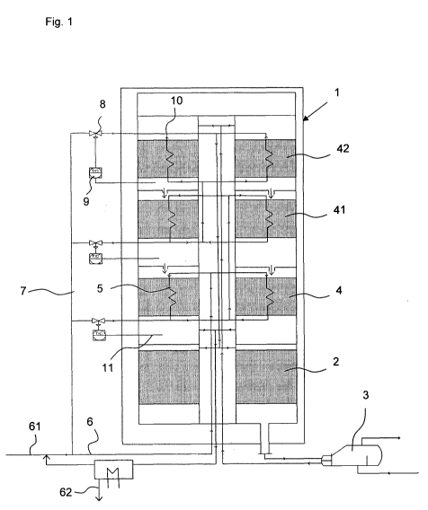
[0025] Fig. 1 shows a schematic view of an apparatus
according to the invention for the synthesis of ammonia in a
reactor with three cooled and one uncooled catalyst bed,
[0026] fig. 2 shows
sketchwise an embodiment of the
invention with a conventional existing ammonia reactor, to
which was connected downstream a "first" reactor according to
the invention with two cooled catalyst bed units,
[0027] fig. 3 shows temperature curves and reaction rate in
an uncooled catalyst bed in a graph with an operating variant
according to the invention (variant 3 from table 1),
[0028] fig. 4 shows temperature curves and reaction rate in
a first cooled catalyst bed in a graph with an operating
variant according to the invention (variant 3 from table 1),
[0029] fig. 5 shows temperature curves and reaction rate in
a second cooled catalyst bed in a graph with an operating
variant according to the invention (variant 3 from table 1),
= CA 02787861 2012-07-23
WO 2010/085926 - 13 -
PCT/DE2009/000111
[0030] fig. 6 shows temperature curves and reaction rate in
a third cooled catalyst bed in a graph with an operating
variant according to the invention (variant 3 from table 1).
[0031] The process according to the invention for the
synthesis of ammonia from a synthesis gas containing nitrogen
N2 and hydrogen H2 can be carried out in an apparatus that
consists of at least one first reactor. Here, the apparatus
comprises a first uncooled catalyst bed unit, at least one
heat exchanger apparatus and at least two cooled catalyst bed
units. The cooling of a catalyst bed unit takes place using a
plurality of cooling pipes, which in each case is arranged in
a catalyst bed unit, and is subsequently also designated as a
"cooling unit". The synthesis gas is fed into a circuit line
starting from a feed apparatus, and firstly flows through the
cooling units assigned to the cooled catalyst bed units,
whereby the synthesis gas absorbs heat. The warmed synthesis
gas then flows through the first uncooled catalyst bed unit,
in which a partial reaction of nitrogen and hydrogen to give
ammonia takes place. The now partially reacted synthesis gas
with a first exit concentration has a markedly raised
temperature and is led through a heat exchanger apparatus in
order to cool the partially reacted synthesis gas. From here,
the partially reacted synthesis gas reaches the cooled
catalyst bed units, in which the further reaction of nitrogen
and hydrogen to give ammonia proceeds up to a second ammonia
exit concentration. The product gas resulting thereby is led
CA 02787861 2012-07-23
WO 2010/085926 - 14 -
PCT/DE2009/000111
to an outlet apparatus, where ammonia condenses out of the
product gas and is drawn off, while unreacted nitrogen and
hydrogen together with fresh nitrogen and hydrogen are fed
into the circuit line by the feed apparatus as synthesis gas.
[0032] In order to now optimize the temperature profile in
the respective cooled catalyst beds for the ammonia
synthesis, the circuit line has at least one bypass line,
which is arranged between the feed apparatus and the first
uncooled catalyst bed unit in parallel to the cooling units
running through the at least two cooled catalyst bed units.
Here, a number of bypass lines can be provided, such that in
each case one bypass line opens into an exit collection
apparatus of a cooling unit of an uncooled catalyst bed, or
that the bypass line runs directly from the feed apparatus to
the first uncooled catalyst bed unit. The fraction of the
synthesis gas that is led through the bypass line, or the
fractions of the synthesis gas that are led through the
bypass lines is/are fixed by a control device which is
connected functionally with a distributor device for the
bypass line and the plurality of cooling pipes. Here, the
control device can be a regulated control device, which
regulates the fraction of the synthesis gas that is led into
the bypass line as a function of a determined process
parameter. The process parameter is measured by means of a
sensor that is functionally coupled to the regulated control
device. This process parameter can be the temperature of the
CA 02787861 2012-07-23
WO 2010/085926 - 15 -
PCT/DE2009/000111
respective cooled catalyst beds, such that their temperature
is optimized by adjustment of the cooling capacity, which
depends on what fraction of the synthesis gas flows through
the cooling units and what is led through the bypass lines.
[0033] From the plurality of cooling pipes and the bypass
line, the synthesis gas is led into the uncooled catalyst bed
unit, which can be an uncooled catalyst bed in the first
reactor; alternatively, it is possible that an existing
reactor that comprises at least one first uncooled catalyst
bed is considered as an uncooled catalyst bed unit. In order
to cool the partially reacted synthesis gas after exit from
the uncooled catalyst bed unit, it is led into a heat
exchanger apparatus, which can be a first of the at least two
cooled catalyst bed units, where a further reaction
simultaneously takes place. Alternatively, the heat exchanger
apparatus can also be a further reactor, which is preferably
a cooled tubular reactor filled with catalyst, by cooling the
partially reacted synthesis gas and allowing it to react
further. A heat exchanger apparatus without reaction is of
course also conceivable, where such a heat exchanger can be
comprised in the first reactor or arranged outside the first
reactor.
[0034] The cooled, partially reacted synthesis gas is now
led to the cooled catalyst bed units, the number of which
comprises up to four, but preferably three, catalyst bed
units. Preferably, at least the last cooled catalyst bed
CA 02787861 2012-07-23
WO 2010/085926 - 16 -
PCT/DE2009/000111
arranged downstream can have a catalyst, the activity of
which is at least twice, preferably five-fold and very
preferably more than seven-fold, the activity of a
conventional iron catalyst. Such a highly active catalyst is,
for example, a barium-activated ruthenium catalyst. After the
reaction in the at least two cooled catalyst bed units, a
product gas that contains ammonia in a second exit
concentration leaves the reactor, is led to the outlet
apparatus, where the separation of the ammonia takes place.
[0035] A further optimization of the temperature in the
cooled catalyst bed units can be carried out by a combination
of co- and countercurrent conduct of the synthesis gas
through the cooling units and of the partially reacted
synthesis gas in the cooled catalyst bed units. In
particular, it is useful at higher pressures to carry out the
cooling in countercurrent flow in the first cooled catalyst
bed, as the reaction rate there is still so high that on
cooling in co-current flow it is not possible to bring the
temperature of the reacting gas close to the optimal
temperature curve. The following catalyst beds are cooled in
co-current flow such that here too an optimal temperature
profile can be achieved and the temperature at the end of the
respective cooled catalyst bed units does not fall so greatly
that the reaction would come to a stop. It has also turned
out to be advantageous that the synthesis gas is first led as
a cooling gas through the plurality of cooling pipes of the
CA 02787861 2012-07-23
WO 2010/085926 - 17 -
PCT/DE2009/000111
last cooled catalyst unit seen downstream and then in each
case flows through the next catalyst bed unit situated
upstream.
[0036] With this apparatus and the process according to the
invention, the first ammonia exit concentration of the
partially reacted synthesis gas after the first uncooled
catalyst bed corresponds here to a proportion by volume of 5
to 25%, whereas the second ammonia exit concentration of the
product gas on leaving the last cooled catalyst bed results
in a proportion by volume of more than 30%, in particular up
to 40%.
[0037] Fig. 1 shows the apparatus according to the invention
in which the process for the synthesis of ammonia is carried
out from nitrogen and hydrogen. A feed apparatus 61 feeds the
circuit line 6 with synthesis gas containing nitrogen and
hydrogen. Generally, an external heat exchanger not shown in
fig. 1 can be arranged in the circuit line 6 after the feed
apparatus 61 and the return apparatus of non-reacted
synthesis gas, which pre-warms the circuit gas including the
fresh synthesis gas. This external heat exchanger normally
has a bypass line assigned to it (likewise not shown), which
is used in order to adjust the entry temperature of the
synthesis gas in the reactor 1 such that the desired
temperature can be achieved on entry into the first uncooled
bed 2.
CA 02787861 2012-07-23
WO 2010/085926 - 18 -
PCT/DE2009/000111
[0038] The circuit line 6 enters the reactor 1 and leads
first in co-current flow through the cooling pipes 5 of the
last cooled catalyst bed 4. An exit apparatus 10 of the
cooling pipes 5 can be designed as an exit collector or as an
exit chamber, into which a first bypass line 7 also opens.
The fraction of synthesis gas that is not led through the
cooling pipes 5 of the last catalyst bed 4 is controlled by
means of the distributor device 8, which is connected to a
sensor 11 that records the exit temperature of the product
gas from the cooled catalyst bed 4. The unreacted synthesis
gas from the cooling pipes 5, or the bypass line 7, is led
into the cooling pipes 5 of the next catalyst bed 41 situated
upstream and conducted in co-current flow. Into the exit
apparatus 10 of the cooling pipes 5 of the second catalyst
bed 41, a second bypass line 7 likewise opens, where here
too, the fraction of the synthesis gas in the bypass line 7
or the cooling pipes 5 takes place in a temperature-
controlled manner. From the exit apparatus 10 for cooling
pipes 5 and bypass line 7 of the second catalyst bed 41, the
synthesis gas is led to the cooling pipes 5 of the first
cooled catalyst bed 42 and there conducted in countercurrent
flow. At an exit apparatus 10, here too the fraction of the
synthesis gas from cooling pipes 5 of the first cooled
catalyst bed 42 and bypass line 7 can be regulated as a
function of the temperature recorded by the sensor 11 by
means of the control device 9. From the exit apparatus 10 of
CA 02787861 2015-07-20
- 19 -
the cooling pipes 5 of the first
cooled catalyst bed unit
42, the unreacted synthesis gas is led to the first uncooled
catalyst bed 2. Nitrogen and hydrogen react there to give
ammonia up to a first exit concentration. The now partially
reacted synthesis gas is conducted from the first uncooled
catalyst bed to a heat exchanger apparatus 3, in order to be
cooled there with steam generation. From the steam generator
3, the partially reacted synthesis gas is fed to the first
cooled catalyst bed 42. After exit from the first cooled
catalyst bed 42, the temperature of the partially reacted
synthesis gas is recorded by means of the sensor 11 and the
fraction of cold synthesis gas is regulated through the
bypass line 7 by means of the control unit 9, in order to
obtain the optimal exit temperature. The partially reacted
synthesis gas next runs through the second cooled catalyst
bed unit 41, in which cooling by the cooling pipes 5 now
takes place in co-current flow. Here too, the fraction of the
synthesis gas functioning as cooling gas is regulated in a
temperature-controlled manner. Finally, the partially reacted
synthesis gas is led through the last catalyst bed unit 4
likewise cooled in co-current flow, such that a product gas
with a second ammonia exit concentration results. From the
last cooled catalyst bed unit 4, the product gas is led to
the outlet apparatus 62 in order to allow ammonia to condense
out and to separate off.
CA 02787861 2012-07-23
WO 2010/085926 - 20 -
PCT/DE2009/000111
[0039] In fig. 2, it is shown schematically how a reactor 1
with two cooled catalyst beds 4, 41 is connected downstream
of an existing reactor 21, which is constructed according to
the prior art. The reactor 21 according to the prior art
contains three uncooled catalyst beds 2, to which in each
case an indirect cooling 3 is connected downstream. Starting
from the synthesis gas feed line 61, the bypass lines 7 lead
in parallel to the circuit line 6 analogously to fig. 1 to
the exit collectors of the plurality of the cooling pipes 5
of the cooled catalyst beds 4, 41. As shown in fig. 2, a
bypass line 7 can extend to the inlet of the existing reactor
21. The fraction of the synthesis gas that does not flow
through the bypass line 7, but takes the path of the circuit
line 6, is first led in co-current flow through the cooling
pipes 5 of the last cooled catalyst bed 4 of the reactor 1
connected downstream. At the exit collector of the cooling
pipes 5, a first synthesis gas fraction from a first bypass
line 7 is combined with the synthesis gas fraction from the
circuit line 6. This is repeated on passage of the synthesis
gas through the plurality of cooling pipes 5 of the first
cooled catalyst bed 41, in the exit collector of which opens
a bypass line 7. The synthesis gas flows through the
plurality of cooling pipes 5 of the first cooled catalyst bed
41 likewise in co-current flow. From there, the synthesis gas
is led through the indirect cooling apparatuses 3 of the
existing reactor 21, before the warmed synthesis gas -
= CA 02787861 2012-07-23
WO 2010/085926 - 21 -
PCT/DE2009/000111
together with the synthesis gas fraction of the third bypass
line 7, which leads to the inlet of the existing reactor 21 -
is led into the three uncooled catalyst beds 2 in order to be
reacted there to give the first exit concentration of
ammonia. The partially reacted synthesis gas, which leaves
the existing reactor 21 with the first exit concentration,
enters the reactor 1 connected downstream and flows through
the two cooled catalyst beds 41 and 4. The product gas with
the second exit concentration of ammonia emerging from the
reactor 1 connected downstream is led to an apparatus for the
condensation and separation of ammonia (not shown), from
which unreacted hydrogen and nitrogen are led back into the
circuit line 6.
EXAMPLE 1
[0040] A first calculated example relates to a process at a
pressure of 200 bar with a synthesis gas entry amount of
26,153 kmol/h. The reactor has an uncooled catalyst bed, an
external waste-heat boiler and three cooled catalyst beds.
The different operating variants are listed in the following
table 1. In this are listed the flow conduct of the cooled
catalyst beds, the catalyst type and the presence of
bypasses. In addition to the catalyst volume, the daily
ammonia production is indicated as a result. The variants 3
to 5 correspond here to a reactor construction as is shown in
= CA 02787861 2012-07-23
WO 2010/085926 - 22 -
PCT/DE2009/000111
fig. 1 with three bypasses and the countercurrent conduct in
the first cooled catalyst bed.
[0041] From the comparison between variant 1 and 2, in which
the first cooled catalyst bed is conducted once in co-current
flow and once in countercurrent flow, it is evident that the
ammonia production in the case of the cooled first catalyst
bed in countercurrent flow slightly increases. With the
integration of the bypasses into the reactor construction,
the cooling area can be enlarged, such that the catalyst
volume decreases, but whereby it is also possible to employ a
catalyst that has a higher activity than the conventional
iron catalyst. With the bypass arrangement and a fresh iron
catalyst, a daily ammonia production is achieved that
corresponds approximately to that of variant 1 with the first
cooled catalyst bed in co-current flow and without bypasses.
If the iron catalyst ages, as shown in variant 4, the
production falls markedly. If a catalyst with a markedly
higher activity is employed, for example an improved iron
catalyst, as in variant 5, a markedly higher daily ammonia
production can be achieved.
[0042] Fig. 3 shows the temperature course (A) and the
reaction rate (0) for the uncooled catalyst bed 2 from fig. 1
according to variant 3 from table 1. The optimal temperature
curve (*) at 200 bar and the equilibrium curve (m) are
furthermore shown in fig. 3. With increasing ammonia
concentration, the reaction rate at first falls, as can be
CA 02787861 2012-07-23
WO 2010/085926 - 23 -
PCT/DE2009/000111
seen in the left area of the curve. If the temperature
approaches the optimal temperature curve, the reaction rate
begins to increase and achieves a maximum at an ammonia molar
fraction of approximately 0.09. This maximum of the reaction
rate is achieved before the temperature curve intersects the
curve of the optimal temperature course (approximately at an
ammonia molar fraction of 0.11), as here the influence of the
ammonia concentration again predominates and thus the
reaction rate again decreases, as can be seen from the right
area of the curve. On exceeding the optimal temperature curve
and approach to the equilibrium curve, the reaction rate
falls steeply.
[0043] The temperature course (A) and the reaction rate (40)
for the first cooled catalyst bed 42 according to variant 3
from table I are shown in fig. 4. In the left area, the
reaction rate is at first constant on account of the approach
of the temperature (A) to the optimal temperature curve (*),
but then begins to fall with increasing ammonia
concentration. If the temperature exceeds the optimal
temperature curve (presently at an ammonia molar fraction of
approximately 0.17), the decrease in the reaction rate
becomes steeper. A further temperature increase is suppressed
by the cooling in countercurrent flow - the course of the
coolant temperature (+) is additionally shown in fig. 4 -
such that the temperature in the first cooled catalyst bed 42
CA 02787861 2012-07-23
WO 2010/085926 - 24 -
PCT/DE2009/000111
does not further approach the equilibrium curve (m), but
again falls to the optimal temperature curve.
[0044] Figs. 5 and 6 show the temperature course (A) and the
reaction rate (0) for the second cooled catalyst bed 41 and
the last cooled catalyst bed 4 according to variant 3 from
table 1. By means of the apparatus or process conduct
according to the invention, the advantageous course of the
temperature virtually along the optimal temperature curve (*)
is now achieved here, such that no approach of the
temperature to the equilibrium curve (m) takes place and the
decrease in the reaction rate is based exclusively on the
increasing ammonia concentration. The coolant temperature (+)
of the second catalyst bed 41 cooled in co-current flow and
last catalyst bed 4 is furthermore shown in fig. 5 and fig.
6.
[0045] Table 2 reproduces the temperature course and amount
and composition of the synthesis gas in a reactor according
to variant 3. With this reactor variant, consisting of an
uncooled catalyst bed, an external waste-heat boiler and
three cooled catalyst beds with iron catalyst, of which the
first cooled catalyst bed is operated in countercurrent flow,
and which has three bypasses, an ammonia exit concentration
of 28.6% by volume is achieved.
CA 02787861 2012-07-23
WO 2010/085926 - 25 -
PCT/DE2009/000111
EXAMPLE 2
[0046] The second calculated example relates to a reactor
with an uncooled catalyst bed, an external waste-heat boiler
and three cooled catalyst beds. In the first two cooled
catalyst beds, a conventional iron catalyst is used, in the
last cooled catalyst bed the highly active ruthenium
catalyst. The three cooled beds are operated in co-current
flow. The catalyst volumes are 218 m3 of iron catalyst and
70 m3 of ruthenium catalyst. This affords with a synthesis
gas amount of 24 533 kmol/h a daily ammonia production of
2000 (metric) tons. This example is carried out at a pressure
of about 100 bar. Using the ruthenium catalyst, an ammonia
exit concentration of 30.5% by volume can be achieved (cf.
table 3).
EXAMPLE 3
[0047] Calculation example 3 relates to a reactor
arrangement as shown in fig. 2. The arrangement consists of a
reactor with three uncooled beds and three internal indirect
heat exchangers and a second reactor with two cooled catalyst
beds. The catalyst volume of the iron catalyst is 46 m3. With
an entry gas amount of 10 804 kmol/h, an ammonia production
of 859 tons per day is achieved. The first exit concentration
from the conventional reactor is 21.6% by volume, where an
exit concentration in the product gas is increased to 27.4%
by volume of ammonia by connection downstream of the second
. CA 02787861 2012-07-23
WO 2010/085926 - 26 -
PCT/DE2009/000111
catalyst with the two cooled catalyst beds. The temperature
course and the pressure range are furthermore evident from
table 4.
'
0
Table 1
t%)
0
I-1
Variant uncooled cooled cat. beds Catalyst Bypasses
Cat. Vol. NH3 prod. o
---
cat. bed co-current countercurrent Fe fresh Fe
old higher act. m3 tons/day 0
CO
cri
1 1 3 0 yes
96.3 2142
t.)
2 1 2 1 yes
96.9 2148 cn
3 1 2 1 yes 3
95.8 2141
4 1 2 1 . yes 3
95,8 1887
1 2 1 yes 3 95,8 2449
0
0
1.)
.-.1
CO
.-.1
Table 2
i co
al
H
N.)
cooled bed 3 cooled bed 2 cooled bed 1 Bed1 Bedl Waste-
heat boiler cooled bed 1 cooled bed 2 cooled bed 3
o
cold in cold in cold in in out out warm out
warm out warm out H
1
I.)
i
0
Temperature ( C) 157.0 205.4 274.5 388.0 532.0 432.0
441.0 420.0 404.0 -.3
1
Pressure (bar) 199.0 198,5 198.0 197.5 197.2 196.4
194.7 193.5 192.4 I.)
u.)
Amount (kmol/h) 26153 26153 26153 26153 24066 24066
22185 21392 20915
Composition
N2 (:X3 by vol.) 24.3 24.3 24.3 24.3 22.0 22.0
19.7 18.5 17.8 ni
H2 (3k by vol.) 72.8 72.8 72.8 . 72.8 66.1 66.1
59,0 55.6 53.4 0
NH3 (% by vol.) 2,8 2.8 2.8 2.8 11.7 11.7
21.2 25.7 28.61-3
-..
CH4 (% by vol.) 0,0 0.0 0.0 0.0 0.0 0.0
0.0 0.0 0.0 ti
Ar (% by vol.) 0.2 0.2 0.2 0.2 0.2 0.2
0.2 0.2PI
0.2 h)
0
0
µc)
--...
0
cb
0
I-1
I-1
I-1
,
Table 3
0
cooled bed 3 cooled bed 2 cooled bed 1 Bed 1 Bed 1 Waste-
heat boiler cooled bed 1 cooled bed 2 cooled bed 3 IQ
. cold in cold in cold in in out
out warm out warm out warm out 1-9
a
Temperature ( C) 97 218 261.1 360 479 432
403 384 355 ===.
o
Pressure (bar) 99.5 99 98.5 98 97.9 97.1
96.8 96.6 96,4 03
Amount (kmol/h) 24533 24533 24533 24533 22872 22872
21721 21140 19640 Ul
1/40
KI
Composition
ch
N2 (% by vol.) 23,8 23.8 23.8 . 23.8 21.9 21.9
20.4 19.6 17,3
H2 (% by vol.) 71.5 71.5 71.5 71.5 65,8 65,8
61.3 58.9 51.9
NH3 (% by vol.) 4.5 4.5 4,5 4.5 12.1 12.1
18.0 21.3 30,5
CH4 (% by vol.) 0.0 0.0 0.0 0.0 0.0 0.0
0.0 0.0 0.0
Ar (% by vol.) 0.2 0.2 0,2 0,2 0.2 0.2
0.2 0.2 0.2
n
0
IV
-.1
Table 4
co
-..3
i
co
1:71
H
N)
Int W13 Int VVT3 Int VVT2 Int VVT1 Bed1 Int WT1 Bed 2
Int VVT2 Bed3 Int W13 cooled bed 1 cooled bed 2 co iv
c)
cold in cold out cold out cold out out warm out out warm
out out warm out out out H
1
IV
I
Temperature ( C) 428 179 250 378 535 407 481 408
450 428 407 399 c)
-..3
Pressure (bar) 230.5 230.0 229.5 229.5 228.6 228.1
227.6 227.1 226.6 226,1 225.0 224.1 i
iv
u.)
Amount (kmolih) 10804 10804 10804 10804 9823 9823
9366 9366 9114 9114 8859 8701
Composition
N2 (% by vol.) 22.3 22.3 22.3 22.3 19,6 19.7 18.1
18.1 17.2 17.2 16,3 15.7
H2 (% by vol.) 67.0 67.0 67.0 67.0 58.7 59.1 54.3
54.3 51.6 51.6 48.8 47.0 hi
NH3 (% by vol.) 2.6 2.6 2.6 2.6 12.9 12.9 18.4 18.4
21.6 21.6 25.1 27,4 0
CH4 (% by vol.) 5.5 5.5 5.5 5.5 6.0 6,0 6.3 6.3 6.5
6.5 6.7 6.8 H
\
Ar (% by vol.) 2.6 2.6 2.6. 2.6 2,8 2.8 3.0 3.0
3.0 3.0 3.1 3.2 ti
P3
IQ
0
0
µ0
\
0
0
0
I-1
I-1
I-I