Note: Descriptions are shown in the official language in which they were submitted.
CA 02787891 2014-09-12
74420-576
METHOD AND APPARATUS FOR ALLOCATING RESOURCES IN A
WIRELESS COMMUNICATION SYSTEM
[Technical Field]
The present invention relates to a wireless
communication system, and more particularly, to a method
and apparatus for allocating resources for a physical
=
channel to a relay.
[Background Art]
Extensive research has been conducted to provide
various types of communication services including voice and
data services in wireless communication systems. In
general, a wireless communication system is a multiple
access system that supports communication with multiple
users by sharing available system resources (e.g., a
bandwidth, transmission power, etc.) among the multiple
users. The multiple access system may adopt a multiple
access scheme such as Code Division Multiple Access (CDMA),
Frequency Division Multiple Access (FDMA), Time Division
Multiple Access (TDMA), Orthogonal Frequency Division
1
CA 02787891 2014-09-12
74420-576
Multiple Access (OFDMA), Single Carrier Frequency Division
Multiple Access (SC-FDMA), or Multi Carrier Frequency Division
Multiple Access (MC-FDMA).
[Disclosure]
According to one aspect of the present invention, =
there is provided a method for receiving downlink signal at a
relay in a wireless communication system, the method
comprising: receiving resource allocation information
indicating a Virtual Resource Block (VRB) set through a Radio
Resource Control (RRC) signaling; receiving a downlink
subframe, starting from a specific Orthogonal Frequency
Division Multiplexing (OFDM) symbol other than first OFDM
symbol of the downlink subframe; monitoring at least part of
the VRB set in the downlink subframe for a Relay Physical
Downlink Control Channel (R-PDCCH); and performing an operation
according to the Downlink Control Information (DCI) of the R-
PDCCH.
According to another aspect of the present invention,
there is provided a relay used in a wireless communication
system, the relay comprising: a Radio Frequency (RF) unit; and
a processor, wherein the processor is configured to: to receive
resource allocation information indicating a Virtual Resource
Block (VRB) set through an Radio Resource Control (RRC)
signaling, to receive a downlink subframe, starting from a
specific Orthogonal Frequency Division Multiplexing (OFDM)
symbol other than first OFDM symbol of the downlink subframe,
to monitor at least part of the VRB set in the downlink
subframe for an Relay Physical Downlink Control Channel (R-
PDCCH), and to perform an operation according to the Downlink
Control Information (DCI) of the R-PDCCH.
2
CA 02787891 2012-10-31
74420-576
According to another aspect of the present invention,
there is provided a method for processing downlink signal at a
relay in a wireless communication system, the method
comprising: receiving a physical control channel signal
including downlink resource allocation information in a 1st
slot of a subframe; and performing an operation for receiving a
physical shared channel signal by using the downlink resource
allocation information, wherein if resources indicated by the
downlink resource allocation information overlap with a
resource block pair where the physical control channel signal
is detected, the 1st slot of the resource block pair is
excluded from the operation for receiving the physical shared
channel signal.
According to another aspect of the present invention,
there is provided a relay used in a wireless communication
system, the relay comprising: a Radio Frequency (RF) unit; anda
processor, wherein the processor is configured: to receive a
physical control channel signal including downlink resource
allocation information in a 1st slot of a subframe, and to
perform an operation for receiving a physical shared channel
signal by using the downlink resource allocation information,
and wherein if resources indicated by the downlink resource
allocation information overlap with a resource block pair where
the physical control channel signal is detected, the 1st slot
of the resource block pair is excluded from the operation for
receiving the physical shared channel signal.
Some embodiments may provide a method and apparatus
for efficiently allocating resources for a physical channel in
3
CA 02787891 2012-10-31
=
74420-576
a wireless communication system, particularly a relay system.
It will be appreciated by persons skilled in the art
that the effects that could be achieved with some embodiments
are not limited to what has been particularly described
hereinabove and the above and other effects that some
embodiments could achieve will be more clearly understood from
the following detailed description taken in conjunction with
the accompanying drawings.
Another aspect provides a method for processing a
downlink signal at a relay in a wireless communication system,
including receiving resource allocation information indicating
a resource block set from a BS through higher layer signaling,
receiving a downlink subframe, starting from a specific
Orthogonal Frequency Division Multiplexing (OFDM) symbol, from
the BS, monitoring the resource block set in the downlink
subframe to receive a physical control channel, and performing
an operation according to the received physical control
channel.
In another aspect, provided herein is a relay used in
a wireless communication system, including a Radio Frequency
(RF) unit, and a processor. The processor is configured to
receive resource allocation information indicating a resource
block set from a BS through higher layer signaling, to receive
a downlink subframe, starting from a specific OFDM symbol, from
the BS, monitors the resource block set in the downlink
subframe to receive a physical control channel, and to perform
an operation according to the received physical control
4
CA 02787891 2012-10-31
74420-576
channel.
In some embodiments, the resource block set may
include a Virtual Resource Block (VRB) set.
In some embodiments, the VRB set may include a
plurality of distributed VRB sets.
In some embodiments, the resource block set may
include a resource block set of a first slot and a resource
block set of a second slot, and the resource block set of the
first slot may be identical to the resource block set of the
second slot.
In some embodiments, the resource allocation
information may include a header and allocation information,
wherein the header indicates a resource allocation type, and
wherein the allocation information includes a bit map
indicating resource blocks, a single bit of the bit map
indicating a resource block or a resource block group in
accordance with the resource allocation type.
In some embodiments, the resource allocation
information may include a resource indication value (RIV), the
RIV being corresponding to a start resource block and a length
of allocated resource blocks.
In some embodiments, the higher layer signaling may
be a radio resource control (RRC) signaling.
In some embodiments, the resource block set may
include a plurality of physical control channel candidates and
5
CA 02787891 2012-10-31
74420-576
a physical control channel indicated to the relay may be masked
by a Radio Network Temporary Identity (RNTI) related with the
relay.
In some embodiments, the downlink subframe may be
received from 3rd OFDM symbol.
In another aspect, provided herein is a method for
processing a downlink signal at a relay in a wireless
communication system, including receiving resource allocation
information indicating a Virtual Resource Block (VRB) set,
receiving a downlink subframe including a plurality of physical
resource blocks (PRBs), starting from a specific Orthogonal
Frequency Division Multiplexing (OFDM) symbol, from the BS; and
performing an operation for receiving a physical control
channel within the VRB set. VRBs within the VRB set are
distributed mapped to the plurality of PRBs.
In a further aspect, provided herein is a relay used
in a wireless communication system, including a Radio Frequency
(RF) unit, and a processor. The processor is configured to
receive resource allocation information indicating a Virtual
Resource Block (VRB) set, to receive a downlink subframe
including a plurality of physical resource blocks (PRBs),
starting from a specific Orthogonal Frequency Division
Multiplexing (OFDM) symbol, from the BS, and to perform an
operation for receiving a physical control channel within the
VRB set. VRBs within the VRB set are distributed mapped to the
plurality of PRBs.
6
CA 02787891 2012-10-31
74420-576
In some embodiments, the physical control channel may
be received on one or more resource blocks without
interleaving.
In some embodiments, the VRBs within the VRB set may
be distributed mapped to PRBs of 1st slot and PRBs of 2nd slot
in a same pattern.
In some embodiments, the VRB set may include a
plurality of distributed VRB sets.
In some embodiments, the VRB set may include a VRB
set of a first slot and a VRB set of a second slot, and the VRB
set of the first slot is identical to the VRB set of the second
slot.
In some embodiments, the VRB set may include a
plurality of physical control channel candidates, and a
physical control channel indicated to the relay is masked by a
Radio Network Temporary Identity (RNTI) related with the relay.
In some embodiments, the downlink subframe may be
received from 3rd OFDM symbol.
In a further aspect, provided herein is a method for
processing a downlink signal at a relay in a wireless
communication system, including receiving a physical control
channel including resource allocation information, and
performing an operation for receiving a physical shared channel
by using the resource allocation information. If resources
indicated by the resource allocation information include a
7
CA 02787891 2012-10-31
74420-576
resource block carrying the physical control channel, a first
slot of the resource block carrying the physical control
channel is excluded from the operation for receiving the
physical shared channel.
In a further aspect, provided herein is a relay used
in a wireless communication system, including an RF unit and a
processor. The processor is configured to receive a physical
control channel including resource allocation information, and
to perform an operation for receiving a physical shared channel
by using to the resource allocation information. If resources
indicated by the resource allocation information include a
resource block carrying the physical control channel, a first
slot of the resource block carrying the physical control
channel is excluded from the operation for receiving the
physical shared channel.
In some embodiments, the physical control channel may
include a Relay Physical Downlink Control Channel (R-PDCCH) and
the physical shared channel may include a Relay Physical
Downlink Shared Channel (R-PDCCH).
In some embodiments, the resource block may include a
Physical Resource Block (PRB).
In some embodiments, the physical control channel may
be interleaved in a plurality of resource blocks.
In some embodiments, if the resources indicated by
the resource allocation information include a resource block
carrying a part of the physical control channel, a first slot
8
CA 02787891 2012-10-31
74420-576
of the resource block carrying the part of the physical control
channel may be excluded from the operation for receiving the
physical shared channel.
In accordance with some embodiments, resources can be
efficiently allocated to a physical channel in a wireless
communication system, particularly a relay system.
It will be appreciated by persons skilled in the art
that the effects that could be achieved with some embodiments
are not limited to what has been particularly described
hereinabove and other advantages of some embodiments will be
more clearly understood from the following detailed description
taken in conjunction with the accompanying drawings.
[Description of Drawings]
The accompanying drawings, which are included to
provide a further understanding of the invention, illustrate
embodiments of the invention and together with the description
serve to explain the principle of the invention.
In the drawings:
FIG. 1 illustrates physical channels and signal
8a
CA 02787891 2012-07-23
WO 2011/093644
PCT/KR2011/000549
transmission on the physical channels in a 3rd Generation
Partnership Project (3GPP) system.
FIG. 2 illustrates a radio frame structure in the
3GPP system.
FIG. 3 illustrates the structure of a downlink
resource grid for the duration of one downlink slot.
FIG. 4 illustrates a downlink subframe structure in
the 3GPP system.
FIG. 5 illustrates an uplink subframe structure in
the 3GPP system.
FIG. 6 illustrates a method for mapping Virtual
Resource Blocks (VRBs) to Physical Resource Blocks (PRBs).
FIGS. 7, 8 and 9 illustrate Resource Allocation (RA)
of type 0, RA of type 1 and RA of type 2, respectively.
FIG. 10 illustrates a wireless communication system
having relays.
FIG. 11 illustrates backhaul transmission in a
Multicast Broadcast Single Frequency Network (MBSFN)
subframe.
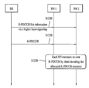
FIG. 12 is a diagram illustrating a signal flow for
allocating resources for a Relay Physical Downlink Control
CHannel (R-PDCCH) and receiving the R-PDCCH using the
allocated resources according to an embodiment of the
present invention.
9
CA 02787891 2012-10-31
74420-576
FIGS. 13 to 17 illustrate methods for multiplexing R-
PDCCHs with R-PDSCHs in resources allocated according to a
DVRB scheme according to embodiments of the present
invention.
FIG. 18 illustrates a method for allocating an R-
PDSCH and decoding and demodulating the R-PDSCH according
to an embodiment of the present invention.
FIG. 19 is a block diagram of a Base Station (BS), a
Relay Node (RN), and a User Equipment (UE) that are
applicable to the present invention.
[Description of Embodiments]
Reference will now be made in detail to the preferred
embodiments of the present invention, examples of which are
illustrated in the accompanying drawings. Embodiments of
the present invention are applicable to a variety of
wireless access technologies such as Code Division Multiple
Access (CDMA), Frequency Division Multiple Access (FDMA),
Time Division Multiple Access (TDMA), Orthogonal Frequency
Division Multiple Access (OFDMA), Single Carrier Frequency
Division Multiple Access (SC-FDMA), and Multi Carrier
Frequency Division Multiple Access (MC-FDMA). CDMA can be
implemented as a wireless technology such as Universal
Terrestrial Radio Access CIENW or CDMA2000. TDMA can be
CA 02787891 2012-07-23
WO 2011/093644
PCT/KR2011/000549
implemented as a wireless technology such as Global System
for Mobile communications (GSM)/General Packet Radio
Service (GPRS)/Enhanced Data Rates for GSM Evolution (EDGE).
OFDMA can be implemented as a wireless technology such as
Institute of Electrical and Electronics Engineers (IEEE)
802.11 (Wireless Fidelity (Wi-Fi)), IEEE 802.16 (Worldwide
interoperability for Microwave Access (WiMAX)), IEEE 802.20,
Evolved UTRA (E-UTRA). UTRA is a part of Universal Mobile
Telecommunications System (UMTS). 3rd
Generation
Partnership Project (3GPP) Long Term Evolution (LTE) is a
part of Evolved UMTS (E-UMTS) using E-UTRA. LTE-Advanced
(LTE-A) is an evolution of 3GPP LTE.
While the following description is given of
embodiments of the present invention with the appreciation
that the technical features of the present invention are
applied to a 3GPP system, this is purely exemplary and thus
should not be construed as limiting the present invention.
FIG. 1 illustrates physical channels and signal
transmission on the physical channels in a 3GPP LTE system.
Referring to FIG. 1, when a User Equipment (UE) is
powered on or enters a new cell, the UE performs an initial
cell search involving acquisition of synchronization with a
Base Station (BS) (S101). For the initial cell search, the
UE receives a Primary Synchronization CHannel (P-SCH) and a
11
CA 02787891 2012-07-23
WO 2011/093644
PCT/KR2011/000549
Secondary Synchronization CHannel (S-SCH) , and acquires
synchronization with the BS and information such as a cell
Identity (ID) from the P-SCH and the S-SCH. Then the UE
may receive a Physical Broadcast CHannel (PBCH) from the BS
and acquire broadcast information within a cell from the
PBCH.
Upon completion of the initial cell search, the UE
may acquire more specific system information by receiving a
Physical Downlink Control CHannel (PDCCH) and receiving a
Physical Downlink Shared CHannel (PDSCH) according to
information carried on the PDCCH (S102).
Meanwhile, if the UE initially accesses the BS or has
no radio resources for signal transmission, the UE may
perform a Random Access (RA) procedure (S103 to S106). For
the RA procedure, the UE may transmit a predefined sequence
as a preamble on a Physical Random Access CHannel (PRACH)
(S103 and S105) and receive a response message to the
preamble on a PDSCH (S104 and S106). If the RA procedure
is contention-based, the UE may additionally perform a
contention resolution procedure.
After the above RA procedure, the UE may receive a
PDCCH/PDSCH (S107) and transmit a Physical Uplink Shared
CHannel (PUSCH)/Physical Uplink Control CHannel (PUCCH)
(S108) in a general uplink/downlink signal transmission
12
CA 02787891 2012-07-23
WO 2011/093644 PCT/KR2011/000549
procedure. Control information that the UE receives from
the BS on a downlink or transmits to the BS on an uplink
includes a downlink/uplink ACKnowledgment/Negative
ACKnowledgment (ACK/N=) signal, a Channel Quality
Indicator (CQI), a Scheduling Request (SR), a Precoding
Matrix Index (PMI), and a Rank Indicator (RI). In the 3GPP
LTE system, the UE may transmit control information such as
a CQI, a PMI and an RI on a PUSCH and/or a PUCCH.
FIG. 2 illustrates a radio frame structure in the
3GPP system.
Referring to FIG. 2, a radio frame is 10ms (307,200
Ts) in duration. The radio subframe is divided into 10
subframes, each subframe being lms long. Each subframe is
further divided into two slots, each of 0.5ms (15,360 TO
duration. Ts represents a sampling time and is given as
T2=1/ (15kHzx2048) =3 .2552x10-8 (about 33ns). A slot is
defined by a plurality of Orthogonal Frequency Division
Multiplexing (OFDM) symbols in time by a plurality of
Resource Blocks (RBs) in frequency. One RB has 12
subcarriers by 7 (6) OFDM symbols in the 3GPP LTE system.
A unit time in which data is transmitted, known as
Transmission Time Interval (TTI) may be defined as one or
more subframes. This radio frame structure is purely
exemplary and thus the number of subframes, the number of
13
CA 02787891 2012-07-23
WO 2011/093644
PCT/KR2011/000549
slots, or the number of OFDM symbols in a radio frame may
vary.
FIG. 3 illustrates the structure of a downlink
resource grid for the duration of one downlink slot.
Referring to FIG. 3, a downlink slot includes 7 (or
6) OFDM symbols in time by NDLRB RBs in frequency. Because
each RB has 12 subcarriers, the downlink slot includes
NDLRBx12 subcarriers in frequency. In the illustrated case
of FIG. 3, the downlink slot has 7 OFDM symbols and each RB
includes 12 subcarriers, which does not limit the scope and
spirit of the present invention. For example, the number
of OFDM symbols per downlink slot depends on the length of
a Cyclic Prefix (CP). Each element in the resource grid is
referred to as a Resource Element (RE). An RE is a minimum
time/frequency resource defined for a physical channel,
indicated by one OFDM symbol index and one subcarrier index.
Each RB includes ArP3L, x N:B REs where 4,, represents the
number of OFDM symbols per downlink slot and N:B represents
the number of subcarriers per RB. The number of RBs per
downlink slot, NDLRB depends on a downlink transmission
bandwidth set by a cell.
FIG. 4 illustrates a downlink subframe structure in
the 3GPP system.
Referring to FIG. 4, a downlink subframe includes a
14
CA 02787891 2012-07-23
WO 2011/093644
PCT/KR2011/000549
plurality of (e.g. 12 or 14) OFDM symbols. A plurality of
OFDM symbols at the start of the downlink subframe are used
for a control region and the other OFDM symbols of the
downlink subframe are used for a data region. The size of
the control region may be determined independently for each
subframe. The control region carries scheduling
information and other Layer 1/Layer 2 (L1/L2) control
information, whereas the data region carries data. Control
channels include a Physical Control Format Indicator
CHannel (PCFICH), a Physical Hybrid automatic repeat
request (ARQ) Indicator CHannel (PHICH), and a Physical
Downlink Control CHannel (PDCCH). Traffic channels include
a Physical Downlink Shared CHannel (PDSCH).
The PDCCH delivers information related to resource
allocation for transport channels, a Paging CHannel (PCH)
and a Downlink Shared CHannel (DL-SCH), an uplink
scheduling grant, and HARQ information to each UE or each
UE group. The PCH and the DL-SCH are delivered on the
PDSCH. Therefore, a BS and a UE transmit and receive data
on the PDSCH except for predetermined control information
or predetermined service data. Control information carried
on the PDCCH is called Downlink Control Information (DCI).
The DCI transports uplink resource allocation information,
downlink resource allocation information, or uplink
CA 02787891 2012-07-23
WO 2011/093644
PCT/KR2011/000549
transmission power control commands for UE groups. Table 1
below illustrates DCI formats according to the contents of
DCI.
[Table 1]
DCI Format Description
DCI format 0 used for the scheduling of PUSCH
DCI format 1 used for the scheduling of one PDSCH codeword
used for the compact scheduling of one PDSCH codeword
DCI format lA
and random access procedure initiated by a PDCCH order
used for the compact scheduling of one PDSCH codeword
DCI format 1B
with precoding information
=DCI format 1C used =for very compact scheduling of one PDSCH codeword
used for the compact scheduling of one PDSCH codeword
DCI format 1D
with precocting and power offset information
used for scheduling PDSCH to UEs -configured in closed-
DCI format 2
loop spatial multiplexing mode
used for scheduling PDSCH to UEs configured in open-loop
DCI =format 2A
spatial multiplexing mode
used for the transmission of TPC commands for PUCCH and
DCI format 3
PUSCH with 2-bit power adjustments
used for the transmission of TPC commands for PUCCH and
DCI format 3A
PUSCH with single bit power adjustments
DCI format 0 conveys uplink resource allocation
information, DCI format 1 to DCI format 2A are used to
indicate downlink resource allocation information, and DCI
format 3 and DCI format 3A indicate Transmit Power Control
(TPC) commands for UE groups. The BS determines a PDCCH
format according to DCI for a UE and adds a Cyclic
16
CA 02787891 2012-07-23
WO 2011/093644
PCT/KR2011/000549
Redundancy Check (CRC) to control information. The CRC is
masked by a unique ID such as a Radio Network Temporary
Identifier (RNTI) according to the owner or purpose of the
PDCCH.
FIG. 5 illustrates an uplink subframe structure in
the 3GPP system.
Referring to FIG. 5, a basic unit for LTE uplink
transmission, a 1-ms subframe 500 includes two 0.5-ms slots
501. On the assumption of a normal CP, each slot has 7
symbols 502, each symbol being an SC-FDMA symbol. An RB
503 is a resource allocation unit defined by 12 subcarriers
in frequency by one slot in time. The LTE uplink subframe
is largely divided into a data region 504 and a control
region 505. The data region 504 refers to communication
resources used to transmit data such as voice data and
packets, including a Physical Uplink Shared CHannel (PUSCH).
The control region 505 refers to communication resources
used for each UE to transmit a downlink channel quality
report, an ACK/NACK for a received downlink signal, and an
uplink scheduling request, including a Physical Uplink
Control CHannel (PUCCH). A Sounding Reference Signal (SRS)
is transmitted in the last SC-FDMA symbol of a subframe in
the time domain and in a data transmission band in the
frequency domain.
SRSs transmitted in the last SC-FDMA
17
CA 02787891 2012-07-23
WO 2011/093644 PCT/KR2011/000549
symbol of the same subframe from a plurality of UEs can be
distinguished by their frequency positions/sequences.
Now a description will be given of RB mapping.
Physical Resource Blocks (PRBs) and Virtual Resource Block
(VRBs) are defined. PRBs are configured as illustrated in
FIG. 3. Specifically, a PRB is a set of 41;1, contiguous
OFDM symbols by Nr contiguous subcarriers. PRBs are
numbered from 0 to Na-1 in the frequency domain. The
relationship between a PRB number npõ and REs (10) in a slot
is given by
[Equation 11
npRB ________________________________________
NRB
sc
_
where k denotes a subcarrier index and Nr denotes the
number of subcarriers in an RB.
A VRB is equal in size to a PRB. Two types of VRBs
are defined, Localized VRBs (LVRBs) and Distributed VRBs
(DVRBs). Irrespective of a VRB type, a pair of VRBs with
the same VRB number nvilE, are mapped to two RBs in the two
slots of a subframe.
FIG. 6 illustrates a method for mapping VRBs to PRBs.
Referring to FIG. 6, LVRBs are mapped directly to
PRBs such that the numbers of the LVRBs, n is identical
18
CA 02787891 2012-07-23
WO 2011/093644
PCT/KR2011/000549
to the numbers of the PRBs, npRB nvRB = npRB ) . VRBs are
numbered from 0 to N8-1 and NaB =NL, . In contrast, DVRBs
are mapped to PRBs after interleaving. More specifically,
a DVRB may be mapped to a PRB as illustrated in Table 2.
=
Table 2 lists RB gaps.
[Table 2]
System BW Gap (Ngap)
1st Gap 2nd Gap
( N RBDL )
( N gap3 ) N gap,2 )
6-10 r-NRBDL 2] N/A
11 4 N/A
12-19 8 N/A
20-26 12 N/A
27-44 18 N/A
45-49 27 N/A
50-63 27 9
64-79 32 16
80-110 48 16
Ngap denotes the frequency spacing between PRBs in the
first and second slots of a subframe, to which VRBs with
the same VRB number are mapped. The frequency spacing may
:
be expressed as the number of PRBs. If 61\r5-49, only one
gN ap,1 ) I f 50 ._c_N RBDI-_110
gap is defined (Ngap
two gaps NgaPj and
NgaP'2 are defined. Ngap
= NgaP3 or NgaP = NgaP'2 is signaled through
downlink scheduling. DVRBs are numbered from 0 to NUB-1.
DL = 1 v ,gap 1
D RBL 2- min(Ng,N: ¨ N gap) = I f Ngap =
Ngap,2
If Ngap N gaP,1 VRB V
19
CA 02787891 2012-07-23
WO 2011/093644
PCT/KR2011/000549
vim- LNDL / 2Ngap j = 2N
v VRB VRB,gap2 RB Pp. min(A, B) represents the smaller
value between A and B.
NDL
VRB consecutive VRB numbers form a VRB number
DL
interleaving unit. If NgaP = NgaP'l = If NgaP = NgaP'2
DL
-Nam =2NPp. VRB number interleaving may be performed using
four columns and Nrow rows in each interleaving unit. Thus,
Nrow=[Ñ/(4P)1=P where P denotes the size of a Resource
Block Group (RBG). An RBG is defined as P consecutive RBs.
VRB numbers are written in a matrix row by row and read
from the matrix column by column. N0.11 nulls are inserted
into the last AC11/2 rows of the second and fourth columns,
N _ _
DL
and null 4Nrow
VRB . The nulls are neglected during reading.
Conventional LTE resource allocations will be
described below. FIGS. 7, 8 and 9 illustrate control
information formats for Resource Allocation (RA) of type 0,
RA of type 1 and RA of type 2 and examples of resource
allocation according to the control information formats.
A UE interprets an RA field according to a detected
PDCCH DCI format. The RA field of each PDCCH includes two
parts, an RA header field and actual RB allocation
information. PDCCH DCI format 1, PDCCH DCI format 2, and
CA 02787891 2012-07-23
WO 2011/093644
PCT/KR2011/000549
PDCCH DCI format 2A are the same in format for RA of type 0
and type 1, and distinguished from one another by their 1-
bit RA header fields according to a downlink system band.
Specifically, type-0 RA and type-1 RA are indicated by 0
and 1, respectively. While PDCCH DCI format 1, PDCCH DCI
format 2, and PDCCH DCI format 2A are used for type-0 RA or
type-1 RA, PDCCH DCI format 1A, PDCCH DCI format 1B, PDCCH
DCI format 1C, and PDCCH DCI format 1D are used for type-2
RA. A PDCCH DCI format for type-2 RA does not have an RA
header field. Resource allocation field indicates a PRB
set of 1st slot. As will be explained below, in case of
resource allocation type 0, 1, 2-LVRB, since there is no
slot hopping between 1st slot and 2nd slot, the same PRB
set is allocated in 2nd slot as allocated in 1st slot (i.e.,
PRB index (1st slot)=PRB index (2nd slot). Meanwhile, in
case of resource allocation type 2-DVRB, if a PRB set of
1st slot is given, a PRB set of 2nd slot is determined
using a slot hopping rule.
Referring to FIG. 7, in RA of type 0, RB allocation
information includes a bitmap indicating RBGs allocated to
a scheduled UE. An RBG is a set of consecutive PRBs. The
size of an RBG, P depends on a system bandwidth as
illustrated in Table 3 below.
[Table 3]
21
CA 02787891 2012-07-23
WO 2011/093644
PCT/KR2011/000549
System Bandwidth RBG Size
Ng- (ID)
1
11 - 26 2
27 - 63 3
64 - 110 4
The total number of RBGs, NRBG for a downlink system
bandwidth of Ng PRBs is given by NRBG [.= Nix, pi
Each of the
[N/ r-]
RBGs is of size P and if AT:modP>0, one of the RBGs
has a size of Ng- .p [NDL Herein,
mod represents a
modulo operation, [1 represents a ceiling function, and LI
represents a flooring function. The size of the bitmap is
NRBG and each bit of the bitmap corresponds to one RBG.
The RBGs are indexed from 0 to NRBG-1 in an ascending order
of frequency. RBG 0 to RBG ATRB(3-1 are sequentially mapped
to the Most Significant Bit (MSB) to the Least Significant
Bit (LSB) of the bitmap.
Referring to FIG. 8, in RA of type 1, RB allocation
information of size NRBG indicates resources of an RBG
subset on a PRB basis to a scheduled UE. An RBG subset p
(0..p<P) includes every Pth RBG, starting from RBG p. The
RB allocation information has three fields. The
first
field with rlog2(P)1 indicates an RBG subset selected from
among P RBG subsets. The second field with one bit
22
CA 02787891 2012-07-23
WO 2011/093644
PCT/KR2011/000549
indicates a shift of a resource allocation span within the
RGB subset. If the bit value is 1, this means that the
shift is triggered and if the bit is 0, this means that the
shift is not triggered. The third field includes a bitmap
in which each bit addresses a single PRB in the selected
RBG subset. The part of the bitmap used to address PRBs in
the selected RBG subset has size NXEI and is defined as
[Equation 2]
=1-4113, .p1
1-1 g2 1
The addressable PRB numbers of the selected RBG
subset start from an offset, Ashth(p) to the smallest PRB
number within the selected RBG subset, which is mapped to
the MSB of the bitmap. The offset is expressed as the
number of PRBs and applied within the selected RBG subset.
If the bit value of the second field for shift of a
resource allocation span is set to 0, the offset for the
RGB subset p is given by A shift (P) =0 . Otherwise, the offset
for the RGB subset p is given by Ashth(p) N RBG subset (p) NTYPE1
NRBG subset ( __\
p) is the number of PRBs in the RGB subset p and is
computed by
[Equation 3]
23
CA 02787891 2012-07-23
WO 2011/093644 PCT/KR2011/000549
1 v
DL NRBDL
RB P+P ,p < ___________ mod
P
P2
m-DL _1 N = DL
NRBRBG subset (p) RB I p (NRBDL 1) mod P +1 ,p= RB ________ mod
P
P2
NRBDL _1l [NRBDL _1
,P> ____________________________________________________________________
modP
P2
Referring to FIG. 9, in RA of type 2, RB allocation
information indicates a set of contiguously allocated LVRBs
or DVRBs to a scheduled UE. In case of RA signaled in
PDCCH DCI format 1A, 1B or 1D, a 1-bit flag indicates
whether LVRBs or DVRBs are allocated. For instance, if the
flag is set to 0, this indicates LVRB allocation and if the
flag is set to 1, this indicates DVRB allocation. On the
other hand, if RA is signaled in PDCCH DCI format 1C, DVRBs
are always allocated. A type-2 RA field includes a
Resource Indication Value (RIV), wherein the RIV is
corresponding to a start resource block It start and a length.
The length represents the number of virtually contiguously
allocated RBs.
FIG. 10 illustrates a wireless communication system
having relays. A relay or Relay Node (RN) extends the
service area of a BS or is installed in a shadowing area to
thereby provide a reliable service. Referring to FIG. 10,
the wireless communication system includes a BS, relays,
and UEs. The UEs communicate with the BS or the relays.
24
CA 02787891 2012-07-23
WO 2011/093644
PCT/KR2011/000549
For the sake of convenience, a UE communicating with a BS
is referred to as a macro UE and a UE communicating with a
relay is referred to as a relay UE. A communication link
between a BS and a macro UE and a communication link
between a relay and a relay UE are referred to as a macro
access link and a relay access link, respectively. A
communication link between a BS and a relay is referred to
as a backhaul link.
Relays are classified into Ll relays, L2 relays, and
L3 relays according to their functionalities in multi-hop
transmission. An Ll relay usually functions as a repeater.
Thus, the L1 relay simply amplifies a signal received from
a BS or a UE and transmits the amplified signal to the UE
or the BS. Because the L1 relay does not decode a received
signal, the transmission delay of the signal is short.
Despite this benefit, noise is also amplified because the
L1 relay does not separate the signal from the noise. To
avert this problem, an advanced repeater or smart repeater
capable of UL power control or self-interference
cancellation may be used. The operation of an L2 relay may
be depicted as decode-and-forward. The L2 relay can
transmit user-plane traffic to L2. While the L2 relay does
not amplify noise, decoding increases transmission delay.
An L3 relay whose operation is depicted as self-backhauling
CA 02787891 2012-07-23
WO 2011/093644
PCT/KR2011/000549
can transmit an Internet Protocol (IP) packet to L3. As it
is equipped with a Radio Resource Control (RRC) function,
the L3 layer serves as a small-size BS.
Ll and L2 relays may be regarded as part of a donor
cell covered by a BS. In the case where a relay is part of
a donor cell, the relay does not have a cell ID of its own
cell ID because it cannot control its cell and UEs of the
cell. Nonetheless, the relay may still have a relay ID.
At least part of Radio Resource Management (RRM) is
controlled by the BS to which the donor cell belongs, while
parts of the RRM may be located in the relay. An L3 relay
can control cells of its own. Then the L3 relay may manage
one or more cells and each of the cells may have a unique
physical-layer cell ID. The L3 relay may have the same RRM
mechanism as a BS. From the perspective of a UE, there is
no difference between accessing a cell controlled by the L3
relay and accessing a cell controlled by a normal BS.
Relays may be classified as follows according to
mobility.
- Fixed RN: as is implied from its appellation, this
type RN is permanently fixed for use in a
shadowing area or for coverage extension. It may
function as a simple repeater.
- Nomadic RN: this type RN is temporarily installed
26
CA 02787891 2012-07-23
WO 2011/093644
PCT/KR2011/000549
when users are rapidly increasing in number, or is
movable within a building.
- Mobile RN: this RN can be installed in a public
transportation vehicle such as a bus or the subway.
The mobility of the RN should be supported.
The following classifications can also be considered
according to the links between relays and networks.
- In-based connection: a network-to-relay link
shares the same frequency band with a network-to-
UE link in a donor cell.
- Out-band connection: a network-to-relay link and a
network-to-UE link use different frequency bands
in a donor cell.
With respect to the knowledge of the existence of a
relay in a UE, relays are classified into the followings.
- Transparent relay: a UE is not aware of whether or
not it is communicating with a network via the
relay.
- Non-transparent relay: a UE is aware of whether or
not it is communicating with a network via the
relay.
FIG. 11 illustrates backhaul transmission in a
Multicast Broadcast Single Frequency Network (MBSFN)
subframe. For in-band relaying, a BS-to-relay link (i.e. a
27
CA 02787891 2012-07-23
WO 2011/093644
PCT/KR2011/000549
backhaul link) operates in the same frequency band as a
relay-to-UE link (i.e. a relay access link). In the case
where a relay transmits a signal to a UE while it is
receiving a signal from a BS or vice versa, the transmitter
and receiver of the relay interfere mutually. Accordingly,
simultaneous BS-to-relay and relay-to-UE transmissions on
the same frequency resources may be limited. For
this
purpose, the backhaul link and the relay access link are
partitioned in Time Division Multiplexing (TDM). In
an
LTE-A system, a backhaul link is established in a subframe
signaled as an MBSFN subframe to support measurements of
legacy LTE UEs located in a relay zone (fake MBSFN). If a
subframe is signaled as an MBSFN subframe, a UE receives
only the control region of the subframe and thus the relay
may configure a backhaul link using the data region of the
subframe. Specifically, the MBSFN subframe is used for BS-
to-relay transmission (e.g. a Relay PDCCH (R-PDCCH) and a
Relay PDSCH (R-PDSCH), starting from the third OFDM symbol
of the MBSFN subframe.
Now, a description will be given of a method for
allocating and managing resources for an R-PDCCH and an R-
PDSCH according to embodiments of the present invention.
An R-PDCCH delivers DCI to a relay. For details of
DCI, refer to Table 1. For example, the R-PDCCH may carry
28
CA 02787891 2012-07-23
WO 2011/093644
PCT/KR2011/000549
downlink scheduling information and uplink scheduling
information to the relay. Downlink data for a relay (e.g.
backhaul data) is received on an R-PDSCH. A communication
procedure on the R-PDCCH and R-PDSCH is performed in the
same manner as or in a similar manner to step S102 of FIG.
1. That is, the relay receives an R-PDCCH and receives
data/control information on an R-PDSCH indicated by the R-
PDCCH. R-
PDCCH transmission processing (e.g. channel
coding, interleaving, multiplexing, etc.) may be carried
out in the same manner as defined by LTE or in a simplified
manner of that defined by LTE, when needed. For instance,
the R-PDCCH transmission processing may be simplified in
view of the nature of relays so that an unnecessary process
as used in LTE is omitted.
The relay demodulates the R-PDSCH based on control
information acquired from the R-PDCCH. Therefore, it is
very important to acquire information about the R-PDCCH
accurately. In the legacy LTE system, a PDCCH candidate
region (i.e. a PDCCH search space) is reserved in a control
region and a PDCCH is transmitted to a specific UE in a
part of the PDCCH candidate region. Accordingly, the UE
acquires its PDCCH from the PDCCH search space through
blind decoding. Similarly, an R-PDCCH may be transmitted
to a relay in the whole or part of reserved resources.
29
CA 02787891 2012-07-23
WO 2011/093644
PCT/KR2011/000549
FIG. 12 is a diagram illustrating a signal flow for
allocating resources for an R-PDCCH and receiving the R-
PDCCH using the allocated resources according to an
embodiment of the present invention.
Referring to FIG. 12, a BS transmits R-PDCCH RA
information to RNs (S1210). The R-PDCCH RA information is
used to reserve an R-PDCCH resource area. Specifically,
the R-RPDCCH RA information indicates the positions of
resources in which an R-PDCCH is likely to be transmitted
to the RNs (a R-PDCCH search space configuration) in
advance. For the sake of conV-enience, the signaling for
reserving R-PDCCH resources in step S1210 will be referred
to Signal #1. Signal #1 may be transmitted through higher
layer signaling such as RRC signaling, MAC signaling, etc.,
preferably RRC signaling. In addition, Signal #1 may be
transmitted in a semi-static manner.
Signal #1 may be
cell-specific, relay group-specific, or relay-specific.
The R-PDCCH search space refers to R-PDCCH resources
(or an R-PDCCH resource area) that an RN is supposed to
monitor to receive its own R-PDCCH. The R-PDCCH search
space includes a relay-common (RN-common) search space
and/or a relay-specific (RN-specific) search space. A
basic unit of the R-PDCCH resources may be an RB (e.g. 12
consecutive subcarriers x 7(6) consecutive OFDM symbols), a
CA 02787891 2012-07-23
WO 2011/093644
PCT/KR2011/000549
Resource Element Group (REG) (e.g. 4 available subcarriers
x 1 OFDM symbol), or a Control Channel Element (COE) (e.g.
a plurality of (for example, 9) REGs).
The R-PDCCH resources (i.e. the R-PDCCH search space)
reserved by Signal #1 are wholly or partially used for a
later actual transmission of an R-PDCCH. In most cases,
only a part of the reserved R-PDCCH resources is used for
R-PDCCH transmission. Meanwhile, an RN should share
resources with a macro UE in the data region of a backhaul
subframe (e.g. an MBSFN subframe). Therefore, it is
preferred that the conventional LVRB/DVRB mapping rules are
still applied to an RN like a macro UE, thereby maximizing
the multiplexing efficiency of a frame. In this context,
Signal #1 is configured based on the same signaling
information as an LTE RA signaling configuration in order
to reserve R-PDCCH resources (e.g. R-PDCCH RBs).
Specifically, Signal #1 may provide VRB mapping
scheme/allocation information. For example, Signal #1 may
provide various VRB mapping scheme/allocation information
illustrated in FIGS. 6 to 9. Preferably, Signal #1 may
include information about contiguous VRBs (e.g. the start
and length of the VRBs), as is done in DVRB allocation
(refer to FIG. 9). Bit configuration in Signal #1 can use
a format of resource allocation types 0, 1 and 2 used in
31
CA 02787891 2012-07-23
WO 2011/093644
PCT/KR2011/000549
the conventional LTE without modification, or use N bits
bitmap when N VRBs are reserved for R-PDCCH in advance.
VRB to PRB mapping can be carried out in accordance with
resource allocation types 0, 1 and 2 of the conventional
LTE. In particular, with the resource allocation types 0,
1 and 2-LVRB, VRB indexes are mapped to PRB indexes of same
value, and with resource allocation type 2-DVRB, VRB
indexes are distributed mapped to PRB indexes.
The number of R-PDCCH RBs reserved by Signal #1 is not
limited to but is preferably a multiple of 4. Benefits
that can be achieved from the number of R-PDCCH RBs being a
multiple of 4 will be described later. A granularity for
R-PDCCH resource allocation may be one RB, One RBG, or a
group of X RBs (e.g. a group of 4 RBs), when needed.
Preferably, the R-PDCCH resource allocation granularity is
4 RBs or a multiple of 4 RBs, which will be detailed later.
In the legacy LTE system, VRB allocation information
(e.g. DVRB RA mapping signaling information) is transmitted
only to one LTE UE. However, RA information (Signal #1)
having the same configuration as or a similar configuration
to the conventional VRB allocation information (e.g. the
conventional DVRB RA mapping signaling information) may be
transmitted to a plurality of (e.g. all) RNs and the RNs
may determine the positions of R-PDCCH resources according
32
CA 02787891 2012-07-23
WO 2011/093644
PCT/KR2011/000549
to a conventional LTE RA rule (e.g. a DVRB interleaving
rule) in an embodiment of the present invention (RN (group)
common signaling). While not shown, Signal #1 may be
transmitted only to one RN, as is conventionally done in
the legacy LTE system (RN dedicated signaling).
When Signal #1 is transmitted through higher layer
signaling on an R-PDSCH, there is no way for an RN to know
a reserved resource area for an R-PDCCH during an initial
access. Accordingly, the RN may assume the existence of an
R-PDCCH in an RB with a specific RB index and decode the R-
PDCCH during the initial access (a UE mode). Then, the RN
may determine a resource area reserved for an R-PDCCH from
Signal #1 received through higher layer signaling (e.g. RRC
signaling) in a semi-static manner (an RN mode). However,
if the reserved R-PDCCH area has been changed, the RN may
not know the exact time when the reserved R-PDCCH has been
changed. As a result, R-PDCCH decoding may be defective.
Even though there is no problem with R-PDCCH decoding, the
RN may have to attempt decoding to detect an R-PDCCH in
many cases. To minimize this problem, the size of the
reserved R-PDCCH area may be increased or decreased by one
basic unit each time it is changed. Obviously, this
information should be considered in determining the
positions and number of R-PDCCH RBs included in semi-static
33
CA 02787891 2012-07-23
WO 2011/093644
PCT/KR2011/000549
RRC signaling. For instance, the reserved R-PDCCH area may
be increased or decreased in size by a multiple of 4 RBs.
In this case, the RN has to detect an R-PDCCH in an extra
R-PDCCH area as well as an existing R-PDCCH area or in a
decreased R-PDCCH area as well as the existing R-PDCCH area
in the vicinity of a subframe having a changed R-PDCCH area
(i.e. before or after the subframe), for example, after
receiving RRC signaling. In
this manner, decoding
complexity caused by an arbitrary R-PDCCH RB configuration
can be reduced.
Meanwhile, if the RN is capable of directly receiving
an R-PDCCH, Signal #1 may be transmitted in DCI of an R-
PDCCH (for example, in the case where a subframe boundary
is a few symbols misaligned between the BS and the RN and
thus the RN can receive an R-PDCCH directly). In this case,
the RN can determine a resource area reserved for an R-
PDCCH on a subframe basis.
Referring to FIG. 12 again, the BS transmits R-PDCCHs
in a backhaul subframe (S1220). The R-PDCCHs may be
transmitted in the whole or part of the R-PDCCH resources
reserved by Signal #1 in step S1210. In most cases, only a
part of M R-PDCCH RBs are used for R-PDCCH transmission.
DCI mapped to R-PDCCH resources (e.g. R-PDCCH RBs), such as
a DL grant (downlink scheduling information) and a UL grant
34
CA 02787891 2012-07-23
WO 2011/093644
PCT/KR2011/000549
(uplink scheduling information), may not be cross-
interleaved. In this case, only a single R-PDCCH is
transmitted in one or more RBs. The DCI mapped to the R-
PDCCH resources may also be intra-RB interleaved. The DCI
mapped to the R-PDCCH resources may also be inter-RB
interleaved (cross-interleaved). In this case, a plurality
of R-PDCCHs may be transmitted together in one or more RBs.
Subsequently, each RN monitors the R-PDCCH resources (the
R-PDCCH resource area) reserved by Signal #1 received in
step S1210 to determine whether there is any R-PDCCH
destined for the RN. Monitoring the R-PDCCH resources
involves blind decoding of R-PDCCH candidates. Upon
detection of its own R-PDCCH, an RN performs an operation
according to the DCI of the R-PDCCH (e.g. downlink
reception, uplink transmission, etc.).
It is regulated that an R-PDCCH carrying a DL grant
(referred to as a DL grant R-PDCCH) is transmitted in the
first slot of a subframe and an R-PDCCH carrying a UL grant
(referred to as a UL grant R-PDCCH) is transmitted in the
second slot of the subframe. Thus, if a DL grant R-PDCCH
exists only in the first slot, the second slot may be
wasted. Accordingly, an R-PDCCH is preferably transmitted
in the second slot. In this regard, an R-PDSCH resource
area allocated to a specific RN may be overlapped with an
CA 02787891 2012-07-23
WO 2011/093644
PCT/KR2011/000549
R-PDCCH resource area reserved for R-PDCCHs, for example,
by RRC signaling. In this case, an RN (or a procedure) may
be configured so as to acquire an R-PDSCH only from the
second slot, for an overlapped RB. To increase resource
utilization, an RN (or a procedure) may be configured such
that an R-PDSCH is demodulated in the second slot, only for
an RB carrying an R-PDCCH, and also in the first slot for
an RB that does not carry an R-PDCCH. In this manner, the
RN can determine the existence of a first R-PDCCH area and
acquire an R-PDSCH from the remaining area, while still
using conventional LTE RA, which will be described again.
With reference to FIGS. 13 to 17, methods for
multiplexing R-PDCCHs with R-PDSCHs in resources allocated
according to a DVRB scheme. For the sake of convenience,
the R-PDCCHs and the R-PDSCHs are shown as transmitted in
the first slot and in the first/second slot, respectively.
However, the R-PDCCH and R-PDSCH transmission is exemplary.
For instance, the R-PDCCHs may be transmitted on a slot
basis in the first and/or second slot. In
LTE-A, a DL
grant R-PDCCH and a UL grant R-PDCCH are transmitted in the
first and second slots, respectively. Unless otherwise
specified, an RB may refer to a VRB or a PRB under
circumstances.
FIG. 13 illustrates a method for multiplexing R-
36
CA 02787891 2012-07-23
WO 2011/093644
PCT/KR2011/000549
PDCCHs with R-PDSCHs in 24 DVRBs, for four RNs. The four
RNs may be a preset RN group scheduled to use the 24
allocated R-PDCCH RBs. That is, the illustrated R-PDCCH
RBs may be dedicated to the RNs (or the RN group). Because
slot-based cyclic shift (DVRB slot hopping) is adopted in
the DVRB scheme, one RN is not allowed to use two slots of
the same PRB. That is, an R-PDCCH (and an R-PDSCH) is not
transmitted to an RN in the two slots of the same PRB. If
the R-PDCCH/R-PDSCH is demodulated using a DeModulation-
Reference Signal (DM-RS), the resulting degraded channel
estimation performance leads to the degradation of
demodulation performance. Considering that an R-PDCCH is
transmitted in a good channel environment in most cases, it
is preferred to allocate the two slots of the same PRB to
the same RN (i.e. an R-PDCCH (and an R-PDSCH)). For this
purpose, DVRB slot hopping may not be applied in DVRB-based
R-PDCCH RA. Resources for an RN are allocated to the same
VRB set in the first and second slots. The slot hopping-
off may apply to all DVRB resources allocated by Signal #1
or to actual resources carrying R-PDCCHs.
As illustrated in FIG. 13, a basic VRB grouping unit
for allocating DVRBs to an RN is a multiple of 4, VRB 4o to
#3, VRB #4 to #7, VRB #12 to #15, or VRB #16 to #19 in an
embodiment of the present invention. Resources for an RN
37
CA 02787891 2012-07-23
WO 2011/093644
PCT/KR2011/000549
are allocated to the same VRB set in the first and second
slots. In spite of DVRB slot hopping, the same PRBs in two
slots may be allocated to the same RN. That is, the same
PRBs of two slots are available to transmission of an R-
PDCCH (and an R-PDSCH) to the same RN through DVRB
allocation.
Therefore, a basic resource allocation unit for an RN
may be 4. For instance, 4 RBs may be a resource allocation
unit for an RN in a situation where backhaul resources are
allocated in both a distributed manner and a localized
manner. Hence, a multiple of 4 RBs can be allocated to an
RN. In this case, the number of bits required for an RA
field may be reduced using an RB step (e.g. step=4). In
addition, even though four RBs (e.g. VRB #0 to #3) are
cyclically shifted in the second slot, each of the
cyclically shifted RBs is adjacent to one of the four RBs
in the first slot. Therefore, even though slot hopping is
off only for M RBs (e.g. an R-PDCCH search space) reserved
for R-PDCCH transmission, the M RBs do not interfere with
other RBs to which slot hopping is applied. For the last
VRB index, two VRBs may be paired, not four VRBs.
Similarly to the above manner, resources for transmission
of an R-PDCCH can be allocated to RN #1, RN #2 and RN #3.
FIG. 14 illustrates another method for multiplexing
38
CA 02787891 2012-07-23
WO 2011/093644
PCT/KR2011/000549
R-PDCCHs with R-PDSCHs in resources allocated according to
the DVRB scheme. Resources of a DVRB resource area assumed
in FIG. 13 are allocated to an RN that does not belong to
the RN group of FIG. 13. In
this manner, resources
allocated to the RN group can be efficiently utilized.
Referring to FIG. 13 again, an R-PDCCH for RN #4 is
not interleaved in the R-PDCCH area (for RN #0 to RN#3) and
thus RN #4 is from another RN group. Let RN #0 to RN#3
form RN Group #1. Then the resources (or resource area) of
FIG. 13 are intended for RN Group #1. In this example,
even though RN #4 is from another RN group, resources may
be allocated to RN #4 for an R-PDCCH and/or an R-PDSCH in
the resources of RN Group #1, thereby increasing resource
use efficiency, as illustrated in FIG. 14. In this case,
information indicating that the resources (area) are
allocated to another RN (RN group) should be transmitted
together with or separately from RA signaling information.
In an embodiment of the present invention, a signal
indicating an RN or an RN group (a Group Indication Signal
(GIS)) may be transmitted. That is, the GIS and a DVRB
signal may be used in allocating resources. The GIS may be
inserted in an RA field or carried in a separate field. If
the GIS does not change often, the GIS may be indicated by
higher layer signaling (e.g. RRC signaling or MAC
39
CA 02787891 2012-07-23
WO 2011/093644
PCT/KR2011/000549
signaling).
FIG. 15 illustrates a third method for multiplexing
R-PDCCHs with R-PDSCHs in resources allocated according to
the DVRB scheme.
This method maximizes resource use
efficiency by modifying a conventional RA.
Referring to FIG. 15, if RN #0 is paired with RN #1
and 4 RBs are configured for them, a common DVRB signal
(PRB #0/6=VRB#0/1/2/3) may be transmitted to RN #0 and RN
#1 to notify them of the allocated resource area and to
instruct them not to follow LTE PDSCH DVRB mapping in the
second slot. That is, the DVRB signal may be reconfigured
so that the first and second slots of the same RB index are
used without slot-based shifting. According to the
conventional DVRB mapping rule, RB #0 in the first slot is
cyclically shifted to RB #12 in the second slot according
to a gap value. However, the cyclic shift may degrade
channel estimation performance and thus demodulation
performance, when an R-PDCCH/R-PDSCH is demodulated using a
DM-RS.
Therefore, an RN may use the same RBs in the first
and second slot without RB shifting in the second slot.
For this operation, additional signaling may not be needed.
A conventional operation mode and a proposed operation mode
may be configured together. For example, shifting-off (i.e.
CA 02787891 2012-07-23
WO 2011/093644
PCT/KR2011/000549
slot hopping-off) is applicable only to RBs to which R-
PDCCHs are actually allocated. Alternatively, shifting-off
may be applied to all RBs of an R-PDCCH search space. For
an R-PDSCH, shifting-off is applicable only when resources
carrying an R-PDCCH are overlapped with resources indicated
by the R-PDCCH. In addition, shifting-off is applicable
only to RBs to which R-PDSCHs are actually allocated.
Shifting-off may also be applicable to all RBs available to
an RN in a backhaul subframe.
FIG. 16 illustrates a fourth method for multiplexing
R-PDCCHs with R-PDSCHs in resources allocated according to
the DVRB scheme.
Referring to FIG. 16, an R-PDCCH resource area is
known to RNs and each RN monitors an R-PDCCH candidate area
(i.e. an R-PDCCH search space) to detect its own R-PDCCH.
In this method, an RN to use the second slot is determined
according to the index of a Relay CCE (R-CCE) to which an
R-PDCCH is allocated for RN #k (k=0, 1, 2, 3). For example,
this method may be carried out based on an R-CCE-index to
RB-index mapping rule which is not restricted to a specific
one. For example, the second slot of an RB carrying an R-
PDCCH may be mapped to an RN corresponding to the R-PDCCH.
To be more specific, if an R-CCE for an R-PDCCH of RN #0 is
mapped to RB #0, an R-CCE for an R-PDCCH of RN #1 is mapped
41
CA 02787891 2012-07-23
WO 2011/093644
PCT/KR2011/000549
to RB #6, an R-CCE for an R-PDCCH of RN #2 is mapped to RB
#12, and an R-CCE for an R-PDCCH of RN #3 is mapped to RB
#18, the second slots of RB #0, 6, 12 and 18 may be mapped
to RN #0, 1, 2, and 3, respectively. Thus, R-PDSCHs and R-
PDCCHs are allocated as illustrated in FIG. 16.
According to the above description, it is possible to
allocate the resources of the second slot of an RB carrying
an R-PDCCH for an RN to the RN (e.g. for an R-PDSCH)
without additional signaling (implicit signaling). The
remaining RBs carrying R-PDSCHs may be allocated to RNs by
RA included in R-PDCCHs. In
this case, an RN may be
configured so as to demodulate an R-PDSCH by distinguishing
RBs carrying R-PDCCHs from RBs that does not carry R-PDCCHs.
For this purpose, the first slot of all RBs (an R-PDCCH
search space) reserved for R-PDCCHs may be excluded from R-
PDSCH transmission (or R-PDSCH demodulation). In another
method, an RN may exclude only the first slot of an RB from
which its own R-PDCCH (it may be restricted to a DL grant
R-PDCCH) is detected from R-PDSCH transmission (or R-PDSCH
demodulation). Specifically, when the RN detects at least
part of a DL grant R-PDCCH in the first slot of a PRB, the
RN may exclude the first slot of the PRB in R-PDSCH
demodulation. In a further method, an RB carrying an R-
PDCCH may be indicated explicitly.
42
CA 02787891 2012-07-23
WO 2011/093644
PCT/KR2011/000549
FIG. 17 illustrates an extension of FIG. 16.
Therefore, it is assumed that the second slot of an RB
carrying an R-PDCCH is implicitly mapped to an RN
corresponding to the R-PDCCH as in FIG. 16. In this case,
if there are a small number of RBs carrying R-PDCCHs due to
a small number of RNs, some RBs may not be allocated in the
second slot, thus wasting resources. This resource waste
may be prevented by increasing a CCE aggregation level.
Referring to FIG. 17, if there are only R-PDCCHs for
two RNs in an R-PDCCH resource area (e.g. 4 RBs), the R-
PDCCHs of the two RNs may be transmitted over the four RBs
by increasing an R-PDCCH R-CCE aggregation level. For this
purpose, a CCE-to-RB mapping rule may be used. The CCE-to-
RB mapping rule is not limited to a specific one. For
instance, R-CCE #0 may be mapped to RB #0, R-CCE #1 may be
mapped to RB #6, R-CCE #2 may be mapped to RB #12, and R-
CCE #3 may be mapped to RB #18. On the assumption of four
R-CCEs for four RBs (i.e. one R-CCE per RB), R-CCE #0 and
#1 may be mapped to RN #0 and R-CCE #2 and #3 may be mapped
to RN #1 (a CCE aggregation level=2). Thus an R-PDSCH for
an RN may be allocated implicitly so as to include one or
more R-PDCCH transmission areas. In the illustrated case
of FIG. 17, the second slots of RB#0 and RB#6 are
implicitly allocated to RN #0 (for an R-PDSCH), and the
43
CA 02787891 2012-07-23
WO 2011/093644
PCT/KR2011/000549
second slots of RB#12 and RB#18 are implicitly allocated to
RN #1 (for an R-PDSCH).
FIG. 18 illustrates a method for allocating an R-
PDSCH and decoding and demodulating the R-PDSCH. This
method does not use implicit mapping between R-CCE indexes
and RB indexes illustrated in FIGS. 16 and 17.
Referring to FIG. 18, a BS transmits a DL grant R-
PDCCH to an RN (S1810). The DL grant R-PDCCH contains R-
PDSCH RA information. Then the BS transmits an R-PDSCH to
the RN (S1820). R-PDSCH RA information indicates resources
of 1st slot only. Therefore, if R-PDCCH is transmitted via
1st slot of a PRB pair and R-PDSCH is transmitted via 2nd
slot of the PRB pair, resources indicated by the R-PDSCH RA
information may include one or more PRB resource on which
R-PDCCH is transmitted.
Thereforethe RN performs an R-
PDSCH reception operation by checking whether the first
slot of an allocated R-PDSCH RB includes an R-PDCCH (i.e.
R-PDCCH resources) (S1830). The R-PDSCH reception involves
R-PDSCH decoding/demodulation.
S1830 will be detailed below. While the following
method is described, centering on an RN, for the sake of
convenience, an operation corresponding to the method
should also be defined for a BS. That is, S1820 and S1830
are configured in relation to each other.
44
CA 02787891 2012-07-23
WO 2011/093644
PCT/KR2011/000549
In one decoding/demodulation method, the RN may
decode/demodulate the R-PDSCH, considering that the first
slot of all RBs reserved for R-PDCCHs (i.e. an R-PDCCH
search space) does not include an R-PDSCH. Because all
resources allocated semi-statically for R-PDCCHs (e.g. RRC
configured R-PDCCH resources) are signaled to the RN, the
RN can determine the positions of the resources. Notably,
a drawback of this method lies in that despite no
transmission of R-PDCCHs in a specific resource area, R-
PDCCHs are regarded as transmitted in the resource area and
thus the resource area is not used for R-PDSCH transmission
(a conservative method).
Another decoding/demodulation method is that the RN
considers that an R-PDCCH exists only in the first slot of
an RB carrying at least part of its own R-PDCCH (it may be
restricted to a DL grant R-PDCCH) (as a result of
interleaving) during R-PDCCH decoding/demodulation. That
is, the RN determines that an R-PDSCH is transmitted only
in the second slot of an RB from which an R-PDCCH is
detected and an R-PDSCH is transmitted also in the first
slot of other R-PDSCH scheduled RBs. Notably, each RN does
not have knowledge of RBs carrying R-PDCCHs for other RNs
and thus does not know the resulting effects. However,
this problem may be solved by imposing a constraint on a
CA 02787891 2012-07-23
WO 2011/093644
PCT/KR2011/000549
scheduler. Specifically, the scheduler may allow one of
RNs to which a part of an R-PDCCH is transmitted in the
first slot of a specific RB to be allocated an R-PDSCH in
the second slot of the specific RB. In addition, the
scheduler may operate such that an R-PDCCH directed to
another RN is not included in an R-PDSCH scheduled RB area
other than an RB carrying a part of an R-PDCCH to an RN.
These are scheduler implementation issues. The RN should
know that it has to perform the above decoding/demodulation
procedure. Accordingly, associated functions should be
contained in implementing an RN (or a procedure), which
should be clarified in any way (a semi-implicit method).
A third decoding/demodulation method is that an RB
carrying an R-PDCCH is explicitly indicated to each RN.
That is, RBs whose first slot is used for actual R-PDCCH
transmission among RBs carrying R-PDSCHs may be notified.
Since the number of RBs to be indicated may vary, a
signaling format indicating the RBs may also vary.
FIG. 19 is a block diagram of a BS, a relay and a UE
which are applicable to the present invention.
Referring to FIG. 19, a wireless communication system
includes a BS 110, an RN 120, and a UE 130.
The BS 110 includes a processor 112, a memory
114, and an RF unit 116. The
processor 112 may be
46
CA 02787891 2012-07-23
WO 2011/093644
PCT/KR2011/000549
configured so as to implement the procedures and/or methods
of the present invention. The memory 114 is connected to
the processor 112 and stores various pieces of information
related to operations of the processor 112. The RF unit
116 is connected to the processor 112 and transmits and/or
receives RF signals. The relay 120 includes a processor
122, a memory 124, and an RF unit 126. The processor 122
may be configured so as to implement the procedures and/or
methods of the present invention. The memory 124 is
connected to the processor 122 and stores various pieces of
information related to operations of the processor 122.
The RF unit 126 is connected to the processor 122 and
transmits and/or receives RF signals. The UE 130 includes
a processor 132, a memory 134, and an RF unit 136. The
processor 132 may be configured so as to implement the
procedures and/or methods of the present invention. The
memory 134 is connected to the processor 132 and stores
various pieces of information related to operations of the
processor 132. The RF unit 136 is connected to the
processor 132 and transmits and/or receives RF signals.
The BS 110, the relay 120 and/or the UE 130 may have a
single or multiple antennas.
[Industrial Applicability]
47
CA 02787891 2012-07-23
WO 2011/093644
PCT/KR2011/000549
The present invention relates to a wireless
communication system. Particularly, the present invention
is applicable to a method and apparatus for allocating
resources for a physical channel to a relay.
The embodiments of the present invention described
hereinbelow are combinations of elements and features of
the present invention. The elements or features may be
considered selective unless otherwise mentioned. Each
element or feature may be practiced without being combined
with other elements or features. Further, an embodiment of
the present invention may be constructed by combining parts
of the elements and/or features. Operation orders
described in embodiments of the present invention may be
rearranged. Some constructions of any one embodiment may
be included in another embodiment and may be replaced with
corresponding constructions of another embodiment. It is
obvious to those skilled in the art that claims that are
not explicitly cited in each other in the appended claims
may be presented in combination as an embodiment of the
present invention or included as a new claim by a
subsequent amendment after the application is filed.
In the embodiments of the present invention, a
description is made, centering on a data transmission and
reception relationship among a BS, a relay, and an MS. In
48
CA 02787891 2012-07-23
WO 2011/093644
PCT/KR2011/000549
some cases, a specific operation described as performed by
the BS may be performed by an upper node of the BS. Namely,
it is apparent that, in a network comprised of a plurality
of network nodes including a BS, various operations
performed for communication with an MS may be performed by
the BS, or network nodes other than the BS. The term 'BS'
may be replaced with the term 'fixed station', 'Node B',
'enhanced Node B (eNode B or eNB)', 'access point', etc.
The term 'UE' may be replaced with the term 'Mobile Station
(MS)', 'Mobile Subscriber Station (MSS)', 'mobile terminal',
etc.
The embodiments of the present invention may be
achieved by various means, for example, hardware, firmware,
software, or a combination thereof. In a hardware
configuration, the methods according to the embodiments of
the present invention may be achieved by one or more
Application Specific Integrated Circuits (ASICs), Digital
Signal Processors (DSPs), Digital Signal Processing Devices
(DSPDs), Programmable Logic Devices (PLDs), Field
Programmable Gate Arrays (FPGAs), processors, controllers,
microcontrollers, microprocessors, etc.
In a firmware or software configuration, the
embodiments of the present invention may be implemented in
the form of a module, a procedure, a function, etc. For
49
CA 02787891 2012-10-31
74420-576
example, software code may be stored in a memory unit .and
executed by a processor. The memory unit is located at the
interior or exterior of the processor and may transmit and
receive data to and from the processor via various known
means.
Those skilled in the art will appreciate that the
present invention may be carried out in other specific
ways than those set forth herein without departing from
the essential characteristics of the present invention.
The above embodiments are therefore to be construed in
all aspects as illustrative and not restrictive. The
scope of the invention should be determined by the
appended claims and their legal equivalents, not by the
above description, and all changes coming within the
meaning and equivalency range of the appended claims
are intended to be embraced therein.