Note: Descriptions are shown in the official language in which they were submitted.
CA 02787981 2014-07-04
-1-
APPARATUS AND METHOD FOR DISTRIBUTING FLUID
BACKGROUND OF THE INVENTION
1. Field of Invention
This invention relates generally to distributing fluid, and more particularly
to methods
and apparatuses for distributing fluid.
2. Description of Related Art
An apparatus for distributing fluid, such as a showerhead, for example, may
receive
fluid and distribute the fluid out a fluid dispensing end for various purposes
such as
bodily cleansing, for example. However, some known apparatuses for bodily
cleansing have only a fixed-size fluid dispensing end, and thus are not easily
adaptable to particular cleaning functions such as cleaning internal orifices,
for
example. Although other known fluid dispensing apparatuses do include
selectable
fluid dispensing ends of different sizes, these known apparatuses do not
provide a
simple mechanism for offering these selectable fluid dispensing ends of
different
sizes. Still other known fluid dispensing apparatuses provide only a single
rate of fluid
flow that is not automatically variable with the selected size of fluid
dispensing end.
These apparatuses may therefore disadvantageously offer too little fluid flow
for
general bodily cleansing, or an unduly high rate of flow for cleansing
internal orifices,
for example.
SUMMARY OF THE INVENTION
In accordance with one aspect of the invention, there is provided a method of
distributing fluid. The method involves receiving the fluid in an opening of a
body,
distributing at least some fluid received in the opening to a first conduit in
communication with a first outlet of a first discharge element coupled to the
body, and
selectively distributing at least some fluid received in the opening, other
than the fluid
distributed to the first conduit, to a second conduit in communication with a
second
CA 02787981 2014-07-04
-2-
outlet of a second discharge element coupled to at least one of the body and
the first
discharge element. Selectively distributing the at least some fluid received
in the
opening to the second conduit involves controlling flow of fluid through a
third conduit in
communication with the opening and in communication with the second conduit
when
the second discharge element is coupled to the at least one of the body and
the first
discharge element. The flow of fluid through the third conduit is controlled
in response to
coupling and decoupling of the second discharge element with the at least one
of the
body and the first discharge element such that fluid is permitted to pass
through the third
conduit when the second discharge element is coupled to the at least one of
the body
and the first discharge element, and such that fluid is prevented from passing
through
the third conduit when the second discharge element is uncoupled with the at
least one
of the body and the first discharge element. The method further involves
distributing at
least some of the fluid received in the first conduit to the second conduit
when the
second discharge element is coupled to the at least one of the body and the
first
discharge element.
Controlling flow of fluid through the third conduit may involve positioning a
valve in an
open position wherein a valve seat of the valve is spaced apart from the third
conduit to
permit fluid to pass through the third conduit when the second discharge
element is
coupled to the at least one of the body and the first discharge element, and
positioning
the valve in a closed position wherein the valve seat contacts a surface
surrounding the
third conduit to prevent fluid from passing through the third conduit when the
second
discharge element is uncoupled with the at least one of the body and the first
discharge
element.
Positioning the valve in the open position may involve transmitting a force
from the
second discharge element to the valve.
Transmitting the force from the second discharge element to the valve may
involve
transmitting the force from the second discharge element to a valve head of
the valve
CA 02787981 2014-07-04
-3-
adjacent the second discharge element when the second discharge element is
coupled
to the at least one of the body and the first discharge element.
Positioning the valve in the closed position may involve resiliently urging
the valve seat
against the surface surrounding the third conduit.
The method may further involve locking the second discharge element to the at
least
one of the body and the first discharge element when the second discharge
element is
coupled to the at least one of the body and the first discharge element.
The method may further involve connecting the body to a fluid source such that
the
opening receives the fluid from the fluid source.
The second discharge element may define a plurality of outlets including the
second
outlet.
The second outlet may be the only outlet of the second discharge element.
The second discharge element may include a fluid dispensing end unitarily
formed with
the second discharge element.
The second discharge element may be attachable to and detachable from a fluid
dispensing end.
Distributing the at least some of the fluid received in the first conduit to
the second
conduit may involve distributing the at least some of the fluid received in
the first
conduit to the second conduit through the first outlet.
In accordance with another aspect of the invention, there is provided an
apparatus for
distributing fluid. The apparatus includes: a body having an opening for
receiving the
fluid; a first discharge element coupled to the body, and having a first
outlet and a first
conduit in communication with the first outlet; means for distributing at
least some fluid
received in the opening to the first conduit; a second discharge element
couplable and
uncouplable with at least one of the body and the first discharge element, and
having a
second outlet and a second conduit in communication with the second outlet;
and
CA 02787981 2014-07-04
-4-
means for selectively controlling flow of at least some fluid received in the
opening,
other than the fluid distributed to the first conduit, to the second conduit.
The means for
selectively controlling flow includes a third conduit in communication with
the opening
and in communication with the second conduit when the second discharge element
is
coupled to the at least one of the body and the first discharge element. The
flow of fluid
through the third conduit is controlled in response to coupling and decoupling
of the
second discharge element with the at least one of the body and the first
discharge
element such that fluid is communicated through the third conduit when the
second
discharge element is coupled to the at least one of the body and the first
discharge
element and such that fluid is prevented from passing through the third
conduit when the
second discharge element is uncoupled with the at least one of the body and
the first
discharge element. The apparatus further includes means for distributing at
least some
fluid received in the first conduit to the second conduit when the second
discharge
element is coupled to the at least one of the body and the first discharge
element.
The means for selectively controlling may further include: a valve having a
valve seat
positionable in an open position wherein the valve seat is spaced apart from
the third
conduit to permit fluid to pass through the third conduit, and in a closed
position wherein
the valve seat contacts a surface surrounding the third conduit to prevent
fluid from
passing through the third conduit; means for positioning the valve in the open
position
when the second discharge element is coupled to the at least one of the body
and the
first discharge element; and means for positioning the valve in the closed
position when
the second discharge element is uncoupled with the at least one of the body
and the
first discharge element.
The means for positioning the valve in the open position may include means for
transmitting a force from the second discharge element to the valve.
The valve may have a valve head adjacent the second discharge element when the
second discharge element is coupled to the at least one of the body and the
first
discharge element, and the means for transmitting the force from the second
discharge
CA 02787981 2014-07-04
-5-
element to the valve may include means for transmitting the force from the
second
discharge element to the valve head of the valve.
The means for positioning the valve in the closed position may include means
for
resiliently urging the valve seat against the surface surrounding the third
conduit and
positioning the valve in the closed position when the second discharge element
is
uncoupled with the at least one of the body and the first discharge element.
The apparatus may further include means for locking the second discharge
element to
the at least one of the body and the first discharge element when the second
discharge
element is coupled to the at least one of the body and the first discharge
element.
The apparatus may further include means for connecting the body to a fluid
source such
that the opening receives the fluid from the fluid source.
The second discharge element may define a plurality of outlets including the
second
outlet.
The second outlet may be the only outlet of the second discharge element.
The second discharge element may include a fluid dispensing end unitarily
formed with
the second discharge element.
The second discharge element may be attachable to and detachable from a fluid
dispensing end.
The apparatus may be a showerhead.
The means for distributing the at least some fluid received in the first
conduit to the
second conduit may include means for distributing the at least some of the
fluid
received in the first conduit to the second conduit through the first outlet.
In accordance with another aspect of the invention, there is provided an
apparatus for
distributing fluid. The apparatus includes: a body having an opening for
receiving the
fluid; a first discharge element coupled to the body, and having a first
outlet and a first
CA 02787981 2014-07-04
-6-
conduit in communication with the first outlet; a fluid distributor operably
configured to
distribute at least some fluid received in the opening to the first conduit;
and a second
discharge element couplable and uncouplable with at least one of the body and
the first
discharge element, and having a second outlet and a second conduit in
communication
with the second outlet. The second discharge element is operably configured to
receive
at least some fluid received in the first conduit when the second discharge
element is
coupled to the at least one of the body and the first discharge element. The
apparatus
further includes a flow controller that selectively controls flow of at least
some fluid
received in the opening, other than the fluid distributed to the first
conduit, to the
second conduit, the flow controller defining a third conduit in communication
with the
opening and in communication with the second discharge element when the second
discharge element is coupled to the at least one of the body and the first
discharge
element. The flow controller includes a valve cooperating with the third
conduit and
being controlled in response to coupling and decoupling of the second
discharge
element with the at least one of the body and the first discharge element such
that fluid
is communicated through the third conduit when the second discharge element is
coupled to the at least one of the body and the first discharge element and
such that
fluid is prevented from passing through the third conduit when the second
discharge
element is uncoupled with the at least one of the body and the first discharge
element.
The valve may have a valve seat, and the valve may be positionable in an open
position
wherein the valve seat is spaced apart from the third conduit to permit fluid
to pass
through the third conduit, and in a closed position wherein the valve seat
contacts a
surface of the flow controller surrounding the third conduit to prevent fluid
from passing
through the third conduit.
The second discharge element may be operably configured to transmit a force to
the
valve and position the valve in the open position when the second discharge
element is
coupled to the at least one of the body and the first discharge element.
CA 02787981 2014-07-04
-6a-
The valve may have a valve head adjacent the second discharge element when the
second discharge element is coupled to the at least one of the body and the
first
discharge element, and the second discharge element may be operably configured
to
transmit the force to the valve head of the valve.
The apparatus may further include a resilient device operably configured to
resiliently
urge the valve in the closed position, and to position the valve in the closed
position
when the second discharge element is uncoupled with the at least one of the
body and
the first discharge element.
The resilient device may be operably configured to contact the valve seat of
the valve to
resiliently urge the valve in the closed position.
The resilient device may include a spring.
The spring may be a coned-disc spring.
The apparatus may further include a lock operably configured to lock the
second
discharge element to the at least one of the body and the first discharge
element when
the second discharge element is coupled to the at least one of the body and
the first
discharge element.
The apparatus may further include a connector operably configured to connect
the body
to a fluid source such that the opening receives the fluid from the fluid
source.
The second discharge element may define a plurality of outlets including the
second
outlet.
The second outlet may be the only outlet of the second discharge element.
The second discharge element may include a fluid dispensing end unitarily
formed with
the second discharge element.
The second discharge element may be attachable to and detachable from a fluid
dispensing end.
CA 02787981 2014-07-04
-6b-
The apparatus may be a showerhead.
The second discharge element may be operably configured to receive the at
least
some fluid received in the first conduit through the first outlet.
Other aspects and features of the present invention will become apparent to
those
ordinarily skilled in the art upon review of the following description of
specific
embodiments of the invention in conjunction with the accompanying figures.
BRIEF DESCRIPTION OF THE DRAWINGS
In drawings that illustrate embodiments of the invention,
Figure 1 is a cross-sectional view of an apparatus for dispensing fluid
in
1 0 accordance with a first embodiment of the invention,
Figure 2 is a cross-sectional view of a body of the apparatus of Figure
1,
CA 02787981 2012-07-24
WO 2011/088544
PCT/CA2010/000119
-7-
Figure 3 is a first cross-sectional view of a first discharge
element of the
apparatus of Figure 1,
Figure 4 is a second cross-sectional view of the first discharge
element of
Figure 3, shown along the line IV-IV shown in Figure 3,
Figure 5 is a cross-sectional view of a second discharge element of the
apparatus of Figure 1,
Figure 6 is a first perspective view of a first valve of the
apparatus of Figure
1,
Figure 7 is a second perspective view of the valve of Figure 6,
Figure 8 is a plan view of the valve of Figure 6,
Figure 9 is a cross-sectional view of the apparatus of Figure 1,
with the
second discharge element of Figure 5 uncoupled from the body of
Figure 2,
Figure 10 is a first cross-sectional view of an apparatus for
dispensing fluid
in accordance with a second embodiment of the invention,
Figure 11 is a cross-sectional view of a body of the apparatus of
Figure 10,
Figure 12 is a first cross-sectional view of a first discharge
element of the
apparatus of Figure 10,
Figure 13 is a second cross-sectional view of the first discharge
apparatus of
Figure 12, shown along the line XIII-XIII shown in Figure 12,
Figure 14 is a cross-sectional view of a second discharge element
of the
apparatus of Figure 10,
Figure 15 is a second cross-sectional view of the apparatus of
Figure 10,
shown along the line XV-XV shown in Figure 10, and
CA 02787981 2012-07-24
WO 2011/088544
PCT/CA2010/000119
-8-
Figure 16 is the cross-sectional view of the apparatus of Figure
10, with the
second discharge element of Figure 14 uncoupled from the body
of Figure 11.
DETAILED DESCRIPTION
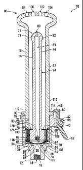
Referring to Figure 1, an apparatus for distributing fluid, in accordance with
a
first embodiment of the invention, is shown generally at 10. The apparatus 10
includes a body 12, a first discharge element 14, and a second discharge
element 16.
Referring to Figure 2, the body 12 has an opening 18 for receiving a fluid. In
the embodiment shown, the body 12 defines internal threads 19 proximate the
opening 18, and the internal threads 19 may cooperate with external threads
of a fluid source (not shown) such as a showerhead hose, for example. The
internal threads 19 thus function as a connector to connect the body 12 to the
fluid source such that the opening 18 receives fluid from the fluid source.
The body 12 in the embodiment shown has an annular wall 21 having an
inner surface 22 that defines a generally cylindrical cavity 24 having an
opening 25. The wall 21 has an annular rim 27 surrounding the opening 25. A
conduit 26 is formed in the body 12 and is in communication with the opening
18 and the cavity 24. Adjacent the opening 25, the inner surface 22 also
defines an annular groove 30 that holds an o-ring 32. The inner surface 22
also has an end portion 34 that defines an annular recess 36 in
communication with the conduit 26.
The wall 21 also has an outer surface 38 and a generally radial projection 40.
The projection 40 includes a pivot 42 for pivotally holding a lock, which in
the
embodiment shown is a lock lever 44. On one side of the pivot 42, the lock
lever 44 has a holding portion 48 having a holding surface 50 facing the rim
27 and spaced apart therefrom for locking the second discharge element 16
(shown in Figure 1) to the body 12. On an opposite side of the pivot 42, the
lock lever 44 also has an actuator portion 52 for receiving a force to rotate
the
lock lever 44 about the pivot 42, thereby moving the holding surface 50 away
CA 02787981 2012-10-15
- 9 -
from the second discharge element 16 to facilitate coupling and uncoupling the
second discharge element 16 with the body 12.
Referring to Figures 3 and 4, the first discharge element 14 includes a
generally
cylindrical base 54. The base 54 has a generally circular end surface 58 and
an
opposed generally annular surface 60. The base 54 also defines axial and
diametrically opposed conduits 62 and 64. The conduits 62 and 64 extend
between respective openings 66 and 68 in the end surface 58 and respective
openings 70 and 72 in the annular surface 60.
The first discharge element 14 also includes an elongate projection 74
extending
axially from the base 54. The projection 74 has a fluid dispensing end shown
generally at 76 having openings that define outlets 78, 80, and 82. Although
three outlets 78, 80, and 82 are shown, the fluid dispensing end 76 may, in
alternative embodiments, include one or more outlets. The projection 74 also
defines a conduit 84 in communication with an opening 86 in the end surface 58
and with the outlets 78, 80, and 82. The first discharge element 14 also
includes
a fluid flow limiter 88 held by an adhesive in the conduit 84 proximate the
opening 86. The fluid flow limiter 88 defines an orifice 90 for permitting
fluid flow
through the conduit 84 at a limited rate.
Referring to Figure 5, the second discharge element 16 includes an elongate
projection 92 defining a conduit 94 therethrough. The projection 92 has a
fluid
dispensing end shown generally at 96, which has openings defining outlets 98,
100, 102, and 104. Although four outlets 98, 100, 102, and 104 are shown, it
will
be appreciated that in alternative embodiments, the fluid dispensing end 96
may
include one or more outlets. The second discharge element 16 is shown
unitarily
formed, although the fluid dispensing end 96 may alternatively be detachable
from the remainder of the projection 92. The projection 92 has an annular end
wall 106 defining an opening 108, and the conduit 94 is in communication with
the opening 108 and with the outlets 98, 100, 102, and 104. The projection 92
has an outer wall 110 defining an annular flange 112 having a holding surface
CA 02787981 2012-10-15
- 10 -
114 for cooperating with the holding surface 50 (shown in Figure 2) to lock
the
second discharge element 16 to the body 12 (shown in Figures 1 and 2).
Referring back to Figure 1, the apparatus 10 includes first and second valves
116
and 118 in the conduits 62 and 64 respectively. Referring to Figures 6, 7, and
8,
the first valve 116 includes a generally tapered valve seat 120 having a
circular
end surface 122, and a valve stem 124 extending axially from the valve seat
120
opposite the end surface 122. The valve stem 124 has a cylindrical outer wall
126 and a valve head 128. The outer wall 126 defines generally radial
projections
130, 132, and 134. The second valve 118 is generally the same as the first
valve
116.
Referring back to Figure 1, in the embodiment shown, the apparatus 10 includes
a coned-disc spring 136 positioned against the end portion 34 of the inner
surface 22 of the body 12 and extending into the annular recess 36. The valve
stem 124 of the first valve 116 is received within the conduit 62 such that
the
valve seat 120 contacts a surface of the base 54 surrounding the opening 66 in
the end surface 58 of the first discharge element 14, and the valve head 128
protrudes out the opening 70 in the annular surface 60. The projections 130,
132,
and 134 (also shown in Figures 6, 7, and 8) slidably contact an inner wall of
the
conduit 62 to center the valve stem 124 of the first valve 116 axially in the
conduit
62. The second valve 118 is similarly received within the conduit 64.
The first discharge element 14 is coupled to the body 12 by fixing, with an
adhesive for example, a portion of the internal surface 22 of the body 12 with
an
outer surface of the base 54 of the first discharge element 14. In this
manner, the
end surface 122 of the first valve 116 contacts the spring 136, as does a
corresponding surface of the second valve 118. Also, the openings 66, 68, and
86 in the end surface 58 of the first discharge element 14 are received within
the
cavity 24 of the body 12 in communication with the conduit 26 and the opening
18, and the conduits 62 and 64 are thus in fluid communication wit the cavity
24,
the conduit 26, and the opening 18.
CA 02787981 2012-10-15
- 11 -
As shown in Figure 1, the second discharge element 16 is coupled to the body
12 by receiving a portion of the projection 92 of the second discharge element
16
in the cavity 24 of the body 12. The annular flange 112 contacts the body 12,
and
the holding surface 114 of the second discharge element 16 contacts the
holding
surface 50 of the lock lever 44. The lock lever 44 thus locks the second
discharge element 16 to the body 12 when the second discharge element 16 is
coupled to the body 12. In alternative embodiments, other mechanisms, such as
a twist lock, quick discharge or camlock, or horseshoe type retainer, for
example,
may lock the second discharge element 16 to the body 12 when the second
discharge element 16 is coupled to the body 12.
As further shown in Figure 1, when the second discharge element 16 is coupled
to the body 12, the conduit 94 is in communication with the openings 70 and 72
of the annular surface 60 of the first discharge element 14, and the conduit
94 is
thus in communication with the conduits 62 and 64. Also, when the second
discharge element 16 is coupled to the body 12, the conduit 94 is in
communication with the outlets 78, 80, and 82 of the first discharge element
14,
and the o-ring 32 contacts the outer wall 110 of the second discharge element
16
to seal the cavity 24. Therefore, when the second discharge element 16 is
coupled to the body 12, at least some of the fluid received in the conduit 84
of the
first discharge element 14 is distributed to the conduit 94 of the second
discharge
element 16, and the conduit 94 of the second discharge element 16 thus
receives at least some fluid received in the conduit 84 of the first discharge
element 14.
Also as shown in Figure 1, when the second discharge element 16 is coupled to
the body 12, the end wall 106 of the second discharge body contacts the valve
head 128 of the first valve 116, and a corresponding surface of the second
valve
118. The valve head 128 of the first valve 116, and a corresponding surface of
the second valve 118, are thus adjacent the second discharge element 16 when
the second discharge element 16 is coupled to the body 12. When the second
discharge element 16 is coupled to the body 12, the second discharge element
CA 02787981 2012-10-15
- 12 -
16 transmits a force on the valve head 128 of the first valve 116, and on a
corresponding surface of the second valve 118. This force causes the first and
second valves 116 and 118 to be urged against the spring 136. The valve seat
120 of the first valve 116 is thus positioned away from the opening 66 of the
first
discharge element 14, and the first valve 116 is in an open position
permitting
fluid to flow from the opening 18 through the conduit 62. Likewise, the second
valve 118 is thus moved to an open position, permitting fluid to flow from the
opening 18 through the conduit 64. Therefore, the end wall 106 of the second
discharge element 16 positions the first and second valves 116 and 118 in the
respective open positions when the second discharge element 16 is coupled to
the body 12.
The lock lever 44 may be urged, by a coil spring (not shown) for example, in a
locked position whereby the holding surface 50 of the lock lever 44 contacts
the
holding surface 114 of the second discharge element 16 to lock the second
discharge element 16 to the body 12 when the second discharge element 16 is
coupled to the body 12. By actuating the actuator portion 52 of the lock lever
44,
the holding surface 50 of the lock lever 44 is separated from the holding
surface
114 of the second discharge element 16, and the second discharge element 16
may be removed from the cavity 24 of the body 12 and thus uncoupled from the
body 12.
Referring to Figure 9, the apparatus 10 is shown with the second discharge
element 16 uncoupled from the body 12. When the second discharge element 16
is uncoupled from the body 12, the end wall 106 of the second discharge
element
no longer contacts the valve head 128 of the first valve 116 or a
corresponding
surface of the second valve 118. The spring 136 contacts the end surface 122
of
the first valve 116, and a corresponding surface of the second valve 118. The
spring 136 thus resiliently urges the end surface 122 of the valve seat 120 of
the
first valve 116 against a portion of the end surface 58 surrounding the
opening 66
of the first discharge element 14, and resiliently urges a corresponding
portion of
the second valve 118 against the opening 68 of the first discharge element 14.
CA 02787981 2012-10-15
- 13 -
The first and second valves 116 and 118 are thus resiliently urged in closed
positions that close the openings 66 and 68, and thereby prevent fluid flowing
through the conduits 62 and 64 respectively, when the second discharge element
16 is uncoupled from the body 12. The spring 136 is therefore a resilient
device
that positions the first and second valves 116 and 118 in the respective
closed
positions when the second discharge element 16 is uncoupled from the body 12.
Referring back to Figure 1, in operation, the body 12 is connected to a fluid
source (not shown) such that the opening 18 receives fluid from the fluid
source.
When the second discharge element 16 is coupled to the body 12, the first and
second valves 116 and 118 are positioned in the respective open positions.
Fluid
received through the opening 18 of the body 12 may therefore pass through the
conduit 26, into the cavity 24, through the conduits 62 and 64, and into the
conduit 94 of the second discharge element 16. Simultaneously, when the
second discharge element 16 is coupled to the body 12, fluid received through
the opening 18 of the body 12 may pass through the conduit 26, into the cavity
24, through the orifice 90 of the fluid flow limiter 88, into the conduit 84
of the first
discharge element 14, out the outlets 78, 80, and 82 of the first discharge
element 14, and into the conduit 94 of the second discharge element 16. The
fluid received in the conduit 94 of the second discharge element 16, which as
described above may be received from the conduit 62, the conduit 64, or the
conduit 84 of the first discharge element 14, exits the second discharge
element
16 through the outlets 98, 100, 102, and 104. Therefore, some fluid received
at
the opening 18 is distributed to the conduit 84 of the first discharge element
14,
and when the user couples the second discharge element 16 to the body 12,
some other fluid received at the opening 18 is thereby selectively distributed
to
the conduit 94 of the second discharge element 16 through the conduits 62 and
64. In some embodiments, the user may couple the second discharge element
16 to the body 12 for ordinary shower use, for example.
Alternatively, a user may actuate the actuator portion 52 and uncouple the
second discharge element 16 from the body 12. When the second discharge
CA 02787981 2012-10-15
- 14 -
element 16 is uncoupled from the body 12, the spring 136 positions the first
and
second valves 116 and 118 in the respective closed positions, and therefore
fluid
received through the opening 18 is prevented from passing through the conduits
62 and 64. Fluid received through the opening 18 may therefore pass through
the
conduit 26, into the cavity 24, through the orifice 90 of the fluid flow
limiter 88,
through the conduit 84 of the first discharge element 14, and out the outlets
78,
80, and 82 thereof. However, when the second discharge element 16 is coupled
to the body 12, additional fluid flows through the conduits 62 and 64.
Therefore,
fluid is discharged from the apparatus 10 at a greater flow rate when the
second
discharge element 16 is coupled to the body 12, and at a reduced flow rate
when
the second discharge element 16 is uncoupled from the body 12.
The first and second valves 116 and 118 therefore co-operate with the first
discharge element 14 to function as a flow controller that selectively
distributes at
least some fluid received in the opening 18 to the conduit 94 of the second
discharge element 16 by selectively controlling flow of fluid through the
conduits
62 and 64 in response to coupling and decoupling of the second discharge
element 16 with the body 12 such that fluid is permitted to pass through the
conduits 62 and 64 when the second discharge element 16 is coupled to the
body 12, and fluid is prevented from passing through the conduits 62 and 64
when the second discharge element 16 is uncoupled from the body 12.
Regardless of whether the second discharge element 16 is coupled to the body
12, the body 12 and the first discharge element 14 act as a fluid distributor
that
distributes at least some fluid received at the opening 18 to the conduit 84
of the
first discharge element 14.
The fluid dispensing end 76 of the first discharge element 14 is smaller than
the
fluid dispensing end 96 of the second discharge element 16, and therefore in
the
operational mode illustrated in Figure 9, the user advantageously has a
reduced
fluid discharge area, and also at a reduced fluid volume as indicated above.
The
operational mode illustrated in Figure 1 may be suitable for general
cleansing, for
example, and the operational mode illustrated in Figure
CA 02787981 2012-07-24
WO 2011/088544
PCT/CA2010/000119
-1 5-
9 may be suitable for particular applications, such as internal bodily
cleansing
also known as douching, for example. The apparatus 10 may therefore
function as a showerhead for cleansing and hygiene, for example.
Referring to Figure 10, an apparatus for distributing fluid, in accordance
with a
second embodiment of the invention, is shown generally at 140. The
apparatus 140 includes a body 142, a first discharge element 144, and a
second discharge element 146.
Referring to Figure 11, the body 142 in the embodiment shown includes a
generally annular wall having a first annular end surface 148 and a second
annular end surface 150. The end surfaces 148 and 150 have respective
openings 152 and 154, and the body 142 has a conduit 156 extending
between the openings 152 and 154. The body 142 defines internal threads
157 proximate the opening 152. The internal threads 157 may cooperate with
internal threads of a fluid source (not shown) such as a showerhead hose, for
example, and the internal threads 157 thus function as a connector to connect
the body 142 to the fluid source such that the opening 152 receives fluid from
the fluid source.
Referring to Figure 12, the first discharge element 144 includes a generally
cylindrical base shown generally at 164 and a projection 166 projecting
axially
from the base 164. The base 164 includes an annular wall 168 having an
inner surface 170 defining a cavity 172. The annular wall 168 also includes an
annular end surface 176, and the base 164 has a circular end surface circular
end surface 178 adjacent the cavity 172. The end surface 178 has a central
opening 180 and diametrically opposed openings 182 and 184 in
communication with the cavity 172.
The base 164 also has a generally cylindrical portion 186 having an outer
surface 188 and a generally annular end surface 190. The outer surface 188
defines an annular groove 192 for holding an 0-ring 194, and the end surface
190 has openings 196 and 198 axially aligned with the openings 182 and 184
respectively of the end surface 178.
CA 02787981 2012-07-24
WO 2011/088544
PCT/CA2010/000119
-16-
Referring to Figures 12 and 13, the generally cylindrical portion 186 of the
base 164 defines a conduit 200 in communication with the opening 180 of the
end surface 178, a conduit 202 in communication with the openings 182 and
196 of the end surfaces 178 and 190 respectively, and a conduit 204 in
communication with the openings 184 and 198 of the end surfaces 178 and
190 respectively.
Referring back to Figure 12, the first discharge element 144 also has a fluid
flow limiter 206 in the conduit 200 proximate the opening 180. The fluid flow
limiter 206 defines an orifice 208 for permitting fluid flow through the
conduit
200 at a limited rate.
The projection 166 has a fluid dispensing end shown generally at 210 and
having openings that define outlets 212, 214, and 216. Although three outlets
212, 214, and 216 are shown, the fluid dispensing end 210 may, in alternative
embodiments, include one or more outlets. The projection 166 also defines a
conduit 218 in communication with the conduit 200, the opening 180, and the
outlets 212, 214, and 216.
Referring to Figure 14, the second discharge element 146 has a generally
annular wall 220, a generally annular end wall 222 adjacent the wall 220, and
an elongate projection 224 projecting axially away from the end wall 222
opposite the wall 220. The wall 220 has a cylindrical inner surface 226 and a
generally annular rim 228. The wall 220 also has a generally radial projection
230 having a pivot 234 for pivotally holding a lock, which in the embodiment
shown is a lock lever 236. On one side of the pivot 234, the lock lever 236
has
a holding portion 238 having a holding surface 240 facing the rim 228 and
spaced apart therefrom for locking the second discharge element 146 to the
first discharge element 144 (shown in Figures 10, 12, and 13). On an opposite
side of the pivot 234, the lock lever 236 also has an actuator portion 242 for
receiving a force to rotate the lock lever 236 about the pivot 234, thereby
moving the holding surface 240 away from the first discharge element 144 to
facilitate coupling and uncoupling the second discharge element 146 with the
first discharge element 144.
CA 02787981 2012-07-24
WO 2011/088544
PCT/CA2010/000119
-17-
The end wall 222 has an inner surface 243, and the inner surfaces 226 and
243 define a generally cylindrical cavity 244.
The projection 224 has a fluid dispensing end shown generally at 246 and
having openings that define outlets 248, 250, and 252. Although three outlets
248, 250, and 252 are shown, the fluid dispensing end 246 may, in alternative
embodiments, include one or more outlets. The second discharge element
146 is shown unitarily formed, although the fluid dispensing end 246 may
alternatively be detachable from the remainder of the projection 224. The
projection 224 also defines a conduit 254 in communication with the cavity
244 and with the outlets 248, 250, and 252.
Referring to Figure 15, the cylindrical portion 186 of the first discharge
element 144 has opposed radially extending generally cylindrical cavities 270
and 272 holding respective coil springs 274 and 276 and respective locks,
which in the embodiment shown are slidable bodies 278 and 280 having
respective holding portions 282 and 284, and respective annular walls 286
and 288 defining respective receptacles 290 and 292 receiving the coil
springs 274 and 276 respectively. The holding portions 282 and 284 have
diameters less than the walls 286 and 288, and thus the walls 286 and 288
are held behind shoulders 294 and 296 respectively formed by the cylindrical
portion 186, and the shoulders 294 and 296 thus hold the bodies 278 and 280
in the cavities 270 and 272 respectively. The wall 220 of the second discharge
element 146 defines radially opposed openings 298 and 300 for receiving the
holding portions 282 and 284 respectively. When the second discharge
element 146 is coupled to the first discharge element 144 as shown in Figure
10, the holding portions 282 and 284 are received in the openings 298 and
300 respectively, and thus cooperate with the lock lever 236 (shown in Figure
10) to lock the second discharge element 146 to the first discharge element
144 when the second discharge element 146 is coupled to the first discharge
element 144. Alternatively, one or more of the lock lever 236 and the bodies
278 and 280 may be omitted.
CA 02787981 2012-07-24
WO 2011/088544
PCT/CA2010/000119
-18-
Referring back to Figure 10, the apparatus 140 includes a first valve 256 in
the conduit 202, and a second valve 258 in the conduit 204. The first and
second valves 256 and 258 are substantially the same as the first valve 116
shown in Figures 6, 7, and 8. The first and second valves 256 and 258
therefore have valve seats 260 and 262 respectively that are substantially the
same as the valve seat 120 shown in Figures 6, 7, and 8, and valve heads
264 and 266 that are substantially the same as the valve head 128 shown in
Figures 6, 7, and 8. The first and second valves 256 and 258 are received in
the conduits 202 and 204 respectively similarly to the first valve 116 in the
conduit 62 (shown in Figure 1). Therefore, the valve seats 260 and 262 of the
first and second valves 256 and 258 respectively are adjacent the openings
182 and 184 respectively of the first discharge element 144. The apparatus
140 also includes a coned-disc spring 268 positioned against the end surface
150 of the body 142.
The first discharge element 144 is coupled to the body 142 by fixing, with an
adhesive for example, a portion of the internal surface 170 of the first
discharge element 144 with a portion of the outer surface 158 of the body
142. In this manner, the valve seats 260 and 262 of the first and second
valves 256 and 258 respectively contact the spring 268. Also, the opening 154
of the body 142 is received within the cavity 172 of the first discharge
element
144 and the conduits 202 and 204 are therefore in communication with the
conduit 156 and opening 152 of the body 142.
As shown in Figure 10, the second discharge element 146 is coupled to the
first discharge element 144 by receiving the projection 166 of the first
discharge element 144 in the conduit 254 of the second discharge element
146, and by receiving the cylindrical portion 186 of the first discharge
element
144 in the cavity 244 (shown in Figure 14) of the second discharge element
146. The 0-ring 194 slidably contacts the inner surface 226 of the second
discharge element 146, and the end surface 190 of the first discharge element
144 contacts the inner surface 243 of the second discharge element 146.
Also, the holding surface 240 of the lock lever 236 contacts the end surface
176 of the first discharge element 144. The lock lever 236 thus locks the
CA 02787981 2012-07-24
WO 2011/088544
PCT/CA2010/000119
-19-
second discharge element 146 to the first discharge element 144 when the
second discharge element 146 is coupled to the first discharge element 144.
Referring to Figure 15, the holding portions 282 and 284 are simultaneously
received in the openings 298 and 300 respectively, and thus also lock the
second discharge element 146 to the first discharge element 144 when the
second discharge element 146 is coupled to the first discharge element 144.
In alternative embodiments, other mechanisms, such as a twist lock, quick
discharge or cam lock, or horseshoe type retainer, for example, may lock the
second discharge element 146 to the first discharge element 144 when the
second discharge element 146 is coupled to the first discharge element 144.
Referring back to Figure 10, when the second discharge element 146 is
coupled to the first discharge element 144, the conduit 254 of the second
discharge element 146 is in communication with the openings 196 and 198,
and thus the conduits 202 and 204, of the first discharge element 144. Also,
as shown in Figure 10, when the second discharge element 146 is coupled to
the first discharge element 144, the conduit 254 of the second discharge
element 146 is in communication with the outlets 212, 214, and 216 of the
first
discharge element 144, and therefore when the second discharge element
146 is coupled to the first discharge element 144, at least some of the fluid
received in the conduit 218 of the first discharge element 144 is distributed
to
the conduit 254 of the second discharge element 146, and the conduit 254 of
the second discharge element 146 thus receives at least some fluid received
in the conduit 218 of the first discharge element 144.
Also as shown in Figure 10, when the second discharge element 146 is
coupled to the first discharge element 144, the inner surface 243 of the
second discharge element 146 contacts the valve heads 264 and 266 of the
first and second valves 256 and 258 respectively. The valve heads 264 and
266 are thus adjacent the second discharge element 146 when the second
discharge element 146 is coupled to the first discharge element 144. When
the second discharge element 146 is coupled to the first discharge element
144, the second discharge element 146 transmits a force on the valve heads
264 and 266. This force causes the first and second valves 256 and 258 to be
CA 02787981 2012-07-24
WO 2011/088544
PCT/CA2010/000119
-20-
urged against the spring 268. The valve seats 260 and 262 are thus
positioned away from the openings 182 and 184 of the first discharge element
144 and the first and second valves 256 and 258 are thus moved to
respective open positions permitting fluid to flow from the opening 152
through the conduits 202 and 204 respectively. Therefore, the inner surface
243 of the end wall 222 of the second discharge element 146 positions the
first and second valves 256 and 258 in the respective open positions when
the second discharge element 146 is coupled to the first discharge element
144.
Referring to Figures 10 and 15, the lock lever 236 may be urged, by a coil
spring (not shown) for example, in a locked position whereby the holding
surface 240 of the lock lever 236 contacts the end surface 176 of the first
discharge element 144 to lock the second discharge element 146 to the first
discharge element 144 when the second discharge element 146 is coupled to
the first discharge element 144. By actuating the actuator portion 242 of the
lock lever 236, the holding surface 240 of the lock lever 236 is separated
from
the end surface 176 of the first discharge element 144. Simultaneously, the
holding portions 282 and 284 may be urged inwards and separated from the
openings 298 and 300 of the second discharge element 146. When the
holding surface 240 of the lock lever 236 is separated from the end surface
176, and the holding portions 282 and 284 are separated from the openings
298 and 300, the second discharge element 146 may be uncoupled from the
first discharge element 144.
Referring to Figure 16, the apparatus 140 is shown with the second discharge
element 146 uncoupled from the first discharge element 144. When the
second discharge element 146 is uncoupled from the first discharge element
144, the inner surface 243 of the second discharge element 146 (shown in
Figure 14) no longer contacts the valve heads 264 and 266 of the first and
second valves 256 and 258 respectively. The spring 268 contacts the valve
seats 260 and 262 of the first and second valves 256 and 258 respectively,
and thus resiliently urges the valve seats 260 and 262 against respective
surfaces portions of the first discharge element 144 surrounding the openings
CA 02787981 2012-07-24
WO 2011/088544
PCT/CA2010/000119
-21-
182 and 184 respectively. The spring 268 thus resiliently urges the first and
second valves 256 and 258 in closed positions that close the openings 182
and 184, thereby preventing fluid flowing through the conduits 202 and 204
respectively when the second discharge element 146 is uncoupled from the
first discharge element 144. The spring 268 is therefore a resilient device
that
positions the first and second valves 256 and 258 in the respective closed
positions when the second discharge element 146 is uncoupled from the first
discharge element 144.
Referring back to Figure 10, in operation, the body 142 is connected to a
fluid
source (not shown) such that the opening 152 receives fluid from the fluid
source. When the second discharge element 146 is coupled to the first
discharge element 144, the first and second valves 256 and 258 are
positioned in the respective open positions. Fluid received through the
opening 152 of the body 142 may therefore pass through the conduit 156, into
the cavity 172, through the conduits 202 and 204, and into the conduit 254 of
the second discharge element 146. Simultaneously, when the second
discharge element 146 is coupled to the first discharge element 144, fluid
received in the opening 152 of the body 142 may pass through the conduit
156, into the cavity 172, through the orifice 208 of the fluid flow limiter
206 into
the conduits 200 and 218 of the first discharge element 144, out the outlets
212, 214, and 216 of the first discharge element 144, and into the conduit 254
of the second discharge element 146. The fluid received in the conduit 254 of
the second discharge element 146, which as described above may be
received from the conduit 202, the conduit 204, or the conduits 200 and 218
of the first discharge element 144, exits the second discharge element 146
through the outlets 248, 250, and 252. Therefore, some fluid received at the
opening 152 is distributed to the conduits 208 and 218 of the first discharge
element 144, and when the user couples the second discharge element 146
to the first discharge element 144, some other fluid received at the opening
152 is thereby selectively distributed to the conduit 254 of the second
discharge element 146. In some embodiments, the user may couple the
CA 02787981 2012-07-24
WO 2011/088544
PCT/CA2010/000119
-22-
second discharge element 146 to the first discharge element 144 for ordinary
shower use, for example.
Alternatively, a user may actuate the actuator portion 242 and the holding
portions 282 and 284 (shown in Figure 15) to uncouple the second discharge
element 146 from the first discharge element 144. When the second
discharge element 146 is uncoupled from the first discharge element 144, the
spring 268 positions the first and second valves 256 and 258 in the respective
closed positions, and therefore fluid received through the opening 152 is
prevented from passing through the conduits 202 and 204. Fluid received
through the opening 152 may therefore pass through the conduit 156, into the
cavity 172, through the orifice 208 of the fluid flow limiter 206 through the
conduits 200 and 218 of the first discharge element 144, and out the outlets
212, 214, and 216 thereof. However, when the second discharge element 146
is coupled to the first discharge element 144, additional fluid flows through
the
conduits 202 and 204 and fluid is discharged from the apparatus 140 at a
greater flow rate when compared to when the second discharge element 146
is uncoupled from the first discharge element 144.
The first and second valves 256 and 258 therefore cooperate with the first
discharge element 144 to function as a flow controller that selectively
distributes at least some fluid received in the opening 152 to the conduit 254
of the second discharge element 146 by selectively controlling flow of fluid
through the conduits 202 and 204 in response to coupling and decoupling of
the second discharge element 146 with the first discharge element 144 such
that fluid is permitted to pass through the conduits 202 and 204 when the
second discharge element 146 is coupled to the first discharge element 144,
and fluid is prevented from passing through the conduits 202 and 204 when
the second discharge element 146 is uncoupled from the first discharge
element 144. Regardless of whether the second discharge element 146 is
coupled to the first discharge element 144, the body 142 and the first
discharge element 144 act as a fluid distributer that distributes at least
some
fluid received at the opening 152 to the conduits 200 and 218 of the first
discharge element 144.
CA 02787981 2012-07-24
WO 2011/088544
PCT/CA2010/000119
-23-
As in the apparatus 10 shown in Figure 1, the fluid dispensing end 210 of the
first discharge element 144 is smaller than the fluid dispensing end 246 of
the
second discharge element 146, and therefore in the operational mode
illustrated in Figure 16, the user advantageously has reduced fluid discharge
area and a reduced fluid volume. The operational mode illustrated in Figure
may be suitable for general cleansing, for example, and the operational
mode illustrated in Figure 16 may be suitable for particular applications,
such
as internal bodily cleansing also known as douching, for example. The
apparatus 140 may therefore function as a showerhead for cleansing and
1 0 hygiene, for example.
While specific embodiments of the invention have been described and
illustrated, such embodiments should be considered illustrative of the
invention only and not as limiting the invention as construed in accordance
with the accompanying claims.