Note: Descriptions are shown in the official language in which they were submitted.
CA 02787987 2012-07-24
WO 2011/100822 PCT/CA2011/000162
SYSTEM AND METHOD FOR CHANNEL STATUS INFORMATION
FEEDBACK IN A WIRELESS COMMUNICATIONS SYSTEM THAT UTILIZES
MULTIPLE-INPUT MULTIPLE-OUTPUT (MIMO) TRANSMISSION
Field of the Disclosure
(0001] The present disclosure relates to wireless communication systems, and
more particularly to a system and method for channel status information (CSI)
feedback in a wireless communications system that utilizes multiple spatial
channels.
Background
[0002] The third generation partnership project (3GPP) is directed towards the
advancement of technology for radio interfaces and network architectures for
wireless communication systems. Multiple-input, multiple-output (MIMO)
techniques have been introduced as one of the key approaches to increase the
peak data rate, average throughput, and system performance in 3GPP LTE (long
term evolution).
[0003] DL MU-MIMO (downlink multi-user MIMO) provides a substantial gain in
DL communications throughput (i.e. DL capacity) by allowing base stations (in
LTE termed evolved Node B or eNB) to transmit information intended for the
multiple users on the same physical time-frequency resources. DL MU-MIMO
transmission is supported by 3GPP LTE Release 8 (Rel-8) and is a potential
technique with some enhancements in LTE-Advanced (Rel-10).
[0004] Performance of MIMO techniques, particularly MU-MIMO, is largely
dependent on the availability of accurate channel state information (CSI) at
the
transmitter (CSIT).
[0005] The receiver at the UE (User Equipment) estimates the CSI by using
reference symbols and could usually obtain an accurate representation of the
CSI. Efficient feedback of this CSI determined at the receiver (CSIR) of the
UE
to the transmitter at the eNB is important for DL MU-MIMO performance,
particularly for an FDD (frequency division duplex) system.
I
CA 02787987 2012-07-24
WO 2011/100822 PCT/CA2011/000162
(0006] Several feedback schemes have been proposed or implemented for
reporting CSI from the UE receiver to the transmitter at the eNB on an uplink
(UL) channel. These feedback schemes can be characterized as different types
of CSI compression techniques.
(0007] One scheme is the feedback of a channel covariance matrix (COVM). In
practice, the COVM is obtained through averaging channel state information
over
frequency and/or time domains. It retains all rank information as well as
large-
scale fading spatial spectrum information, including angle of departure (AOD)
and power. Long term averaging may be used to reduce the UL feedback
overhead. However, small scale fading information is lost in this case. This
approach quantizes each complex element of the COVM and could result in a
large feedback overhead.
(0008] Another scheme is the principal eigenvector feedback, in which only one
(the principal) eigenvector of the channel matrix is reported to the
transmitter.
This may be viewed as a further compression of the channel COVM. While, the
principal eigenvector is a good approximation of the COVM in highly correlated
channels, in an uncorrelated channel with higher rank, this approximation will
lose information on non-principal ranks. It is similar to COVM feedback
scheme,
but with fewer elements to be quantized and reported.
[0009] In 3GPP LTE Rel-8, a codebook based precoding scheme with limited-CSI
feedback is adopted based on a predefined codebook in which a set of
codewords is defined based on the Householder (HH) transform. The UE reports
the index of the codeword, or so-called precoding matrix index (PMI) at each
reporting instance. This scheme has a low feedback overhead compared with the
other schemes as mentioned above.
[0010] In the codebook based scheme, a UE estimates its channels and
quantizes the estimated channels by using a codebook. At the UE a codeword
with the best representation of the measured normalized channel is selected
from the codebook and the index of the selected codeword, or the PMI, is then
fed back from the UE to the eNB transmitter.
2
CA 02787987 2012-07-24
WO 2011/100822 PCT/CA2011/000162
[0011] The amount of quantization error in the PMI feedback approach depends
on codebook size and specific codebook design. Quantization error is more
tolerable for single-user MIMO (SU-MIMO), but could degrade MU-MIMO
performance significantly. Quantization error could be reduced by using a
larger
sized codebook, however, it may be impractical to use a very large codebook as
it requires a large storage space at both the UE and the eNB as well as more
processing time for codebook searching. Moreover, using a large codebook
would lead to undesirably large feedback overhead.
Brief Description of the Drawings
[0012] The present disclosure will be better understood with reference to
drawings in which:
FIG. I is a block diagram illustrating an exemplary system architecture for a
LTE
MIMO communication system;
FIG. 2 shows an example precoding codebook for transmission on four antennas
FIG. 3 is graphically representation of quantization error vector in a PMI
feedback
approach;
FIG. 4 is a flow chart for determining quantization error according to an
embodiment of the present matter;
FIG. 5 is a flow chart for reporting of the quantization error vector
according to an
embodiment of the present matter;
FIG. 6 shows an example transform based codebook;
FIG. 7 is a graphical representation of basis transformation according to an
embodiment of the present matter;
FIG. 8 is a flow chart for generating an error vector according to an
embodiment
of the present matter;
FIG. 9 is a graphical representation of a timeline for reporting of error
vectors
according to an embodiment of the present matter;
FIG. 10 is a graphical representation showing the reporting of a sequence of
bits
of the quantized error;
3
CA 02787987 2012-07-24
WO 2011/100822 PCT/CA2011/000162
FIGs. 11a and 11b are graphs showing the error converging with variable or
fixed step sizes according to embodiments of the present matter;
FIG. 12 is a graph of simulation results; and
FIG. 13 is a block diagram of an exemplary UE and eNB according to the present
matter
Detailed Description
[0013] When referred to herein, the terminology user equipment (UE) includes
but is not limited to a wireless transmit/receive unit (WTRU), a mobile
station, a
fixed or mobile subscriber unit, a pager, a cellular telephone, a personal
digital
assistant (PDA), a computer, or any other type of user device capable of
operating in a wireless environment.
[0014] When referred to herein, the terminology "eNB" includes but is not
limited
to a Node-B, a base station, a site controller, an access point (AP), or any
other
type of interfacing device capable of operating in a wireless environment.
[0015] The present disclosure provides a feedback method for feedback of CSI
from a UE to an base station for MIMO transmission. The feedback method may
be used with current feedback schemes such as that described in LTE Rel-8, and
may reduce the channel quantization error induced by the codebook-based
methods as for example described in Rel-8.
[0016] The present disclosure describes a feedback method which provides a
more accurate feedback of CSIR for use by an base station scheduler and its
MIMO precoder, for improving DL MIMO performance, particularly for MU-MIMO
transmission.
[0017] In general, the present method quantizes an error vector in a quantized
CSI to form one or more error measure indicator (EMI) messages, each
including quantization error information for the quantized CSI.
[0018] The quantized CSI may be reported by a typical PMI based feedback
scheme. The EMI messages may then be fed back to the base station and could
be used with the reported CSI to improve the accuracy of a reconstructed CSI
at
the base station. Furthermore, the present approach may reduce feedback
overhead by using a fewer number of bits to represent each of the EMI
4
CA 02787987 2012-07-24
WO 2011/100822 PCT/CA2011/000162
messages The EMI messages allow more accurate reconstruction of a principal
eigenvector of an actual channel matrix at the base station.
[0019] Still further the EMI messages may be progressively reported to the
base
station. The number of EMI reports may be configurable and EMI reporting could
be done incrementally. The more EMI reports an base station receives,, the
more
accurate CSI it could reconstruct.
[0020] Conversely, if the increased signaling overhead due to EMI reporting
cannot be tolerated, the EMI reporting can be balanced by reducing
conventional
PMI reporting frequency. For example, in low mobility and highly correlated
scenarios, where channel variation is small, the EMI report provides more
value
than the PMI report as the PMI may not change much. Therefore, PMI reporting
with a longer report period is acceptable. This reduction in usage of UL
signaling
can be used instead for the EMI reporting. As low mobility and high
correlation
are also the scenarios where DL MU-MIMO could be deployed, the use of an
EMI may allow the base station to improve DL MU-MIMO performance.
[0021] A rank-1 channel is assumed in the following description for
simplicity.
However the description may be extended to multiple-rank channels.
[0022] In accordance with one aspect of the present matter there is provided a
method for user equipment operation in a wireless communication system, the
wireless communication system having an base station, the method comprising
measuring a channel between the UE and the base station, determining a
quantized estimate using a codebook to approximate the measured channel,
computing an error measure for the quantized estimate and transmitting the
error
measure and the quantized estimate to the base station for use by the base
station in reconstructing an actual channel vector
[0023] In accordance with one aspect the error measure includes information of
which basis and which dimension in the basis are selected as a quantized
channel estimate, and the error measure contain remaining basis dimensions
information and said projections onto said remaining basis dimensions.
[0024] In accordance with another aspect of the present matter there is a
provided a method for base station operation in a wireless communication
CA 02787987 2012-07-24
WO 2011/100822 PCT/CA2011/900162
system comprising receiving at the base station an error measure and a
quantized estimate of a channel from an EU, the quantized estimate being a
codebook based approximation of a measured channel between the UE and the
base station, the error measure being an error vector corresponding to a
difference between the quantized estimate and the measured channel; and
reconstructing the channel at the base station by applying the error measure
to
the quantized estimate to derive a channel vector between the base station and
the UE.
[0025] In accordance with a still further aspect there is provided a mobile
device
for operation in a wireless communication system, the wireless communication
system having an base station, the mobile device comprising a processor
configured for:
measuring a channel between the UE and the base station; determining a
quantized estimate using a codebook to approximate the measured channel;
computing an error measure for the quantized estimate; and transmitting the
error measure and the quantized estimate to the base station for use by the
base
station in reconstructing an actual channel vector.
[0026] In accordance with a still further aspect there is provided a MIMO
system
comprising a mobile device, having a processor configured for: measuring a
channel between the mobile device and a base station; determining a quantized
estimate using a codebook to approximate the measured channel; computing an
error measure for the quantized estimate; and transmitting the error measure
and
the quantized estimate to the base station for use by the base station in
reconstructing an actual channel vector.
[0027] There is further provided in the system, wherein the base station
includes
a processor and communication subsystem configured for: receiving at the base
station the error measure and the quantized estimate of the channel from the
mobile device; and reconstructing a representation of the actual channel
vector
at the base station by applying the error measure to the quantized estimate.
[0028] The system further provides for the use by the base station of the
actual
channel vector in MIMO communications.
6
CA 02787987 2012-07-24
WO 2011/100822 PCT/CA2011/000162
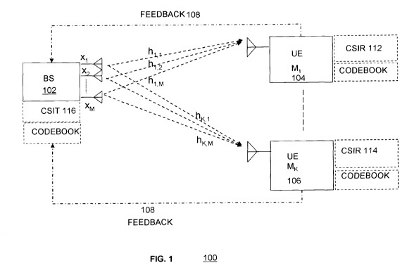
[0029] Referring to Fig. 1 there is shown a schematic representation of an
example DL MU-MIMO mobile communication system with feedback 100. As
mentioned, the communication system 100, according to one embodiment, is an
LTE or LTE-Advanced system. The system includes a base station (BS) or
called an eNB in LTE 102 and a plurality of independent mobile user terminals
(UE's) 104,106 distributed within wireless covering range of the base station.
The eNB is equipped with a plurality of antennas and each of the UE's are
equipped with one antenna coupled to appropriate receivers and processing
circuitry. It is to be noted that a single UE antenna is illustrated for
simplicity and
ease of description; however a UE could have more than one antenna in which
case the mathematical representations described below would extend to matrix
operations.
[0030] As is well known to those skilled in the art, DL MU-MIMO, also known as
a
MIMO broadcast system with feedback is organized as follows. The eNB is
assumed to be equipped with M transmitting antennas, transmits independent
messages to K UEs' (i.e., receivers). Each of these K receivers is equipped
with
one or more antennas (one antenna is exemplified). In particular, the eNB
transmits signal xi from the j-th antenna where xj is from the set of complex
numbers. Thus, an eNB with M antennas transmits a vector x=(x,, ... , xM) at
any given instance.
[0031] During transmission from the j-th antenna to the k-th UE, the effect of
channel on the transmitted signal x; is modeled by multiplying it with a
channel
coefficient hk.,. As is well known to those of ordinary skill in the art, the
channel
coefficient of a mobile communications channel represents the effect of the
environment on the transmitted signal. Thus, for a UE with one antenna, when
the vector x is transmitted by the eNB, the UE k actually receives the signal
yk=hkx+nk, where hk=(hk,l, ... , hk,M) is a row vector containing channel
coefficients from all transmit antennas of the eNB to the receive antenna of
the k-
th UE, and nk contains additive Gaussian white noise and interference. For a
UE
with multiple antennas the channel vector hk is a matrix and is termed a
channel
matrix H
7
CA 02787987 2012-07-24
WO 2011/100822 PCT/CA2011/000162
[0032] As is well known the eNB may send well defined reference symbols to the
UE's and the UE uses these reference symbols to measure their respective
channel vectors hk,from the eNB. Next, the k-th mobile terminal (k=1, ... , K)
determines a quantized version of the measured channel vector hk, typically by
selecting a codeword in the predefined codebook that best represents the
normalized measured channel vector. The codebook is normally pre-determined
and known to each of the UE's and also to the eNB and could be represented by,
C={c1, c2 ... , cr} where each of codebook entries comprises an M-element
complex vector for rank-1 transmission. The selected codeword is used to
represent (i.e., by approximating) the actual (i.e., as measured) channel
vector.
In particular, the k-th UE determines the index tk of the selected codeword
and
thus as mentioned above, the selected codeword is a "quantized" (i.e.,
approximated) version of the channel vector hk.
[0033] After the k-th mobile terminal has selected a codeword to represent its
channel vector, it transmits the index (PMI) thereof, tk, back to the eNB,
thereby
indicating to the eNB the (approximate) value of the normalized measured
channel vector hk. That is, since the codebook used by the UEs is pre-
determined and is also known by the eNB, the indices tk, would allow the eNB
to
reconstruct the quantized versions of the channel vectors hk, for the k-th UE.
An
eNB employing DL MU- MIMO broadcast techniques would then choose a subset
of L UEs from among the K UEs and schedule corresponding transmissions to
the UEs in MU-MIMO transmission. The selection of such UE could be based on
performance criteria, e.g., minimizing inter-user interference or maximizing
system throughput, and such performance criteria would use the information of
the reconstructed channel vectors at the eNB. As noted the above discussion
pertains to a single antenna receiver, for UEs with multiple receive antennas,
the
receiver estimates a channel matrix H, based on the reference signals and
finds
a codeword, which may be with a single rank or multiple-rank, in the pre-
determined codebook that best matches the measured channel matrix, and feeds
back the index of such codeword(s) (PMI) to the eNB. The NB may follow the
8
CA 02787987 2012-07-24
WO 2011/100822 PCT/CA2011/000162
similar procedure as described above to select a number of UEs in MU-MIMO
transmission.
[0034] Referring to FIG. 2 there is shown a tabular representation of a
precoding
codebook for transmission on four antennas as defined in LTE Rel-8. In FIG. 2
the first column 201 denotes the codebook index and the second column 202
denotes the unit vector (u;), which is used to construct a Householder matrix
W;
with equation W; = I - 2u;u;' /u;'u; The third column 204 (W 0}) in the table
denotes the jth column of the Householder matrix constructed using the ith
unit
vector u;. As mentioned earlier, in LTE ReI-8 the UE is specified to report
the
index of the codeword, as a 4-bit value (called a label) or the so-called PMI
at
each reporting time. Codebook entries for multilayer transmission are also
shown
in FIG. 2. Although a LTE Rel-8 codebook is illustrated it is appreciated that
other
codebooks may be used.
[0035] As seen from the above, given a limited number of codewords (sixteen in
FIG.2 as an example) the quantization error is introduced by approximating the
actual channel vector with a codeword in codebook. This error is shown
graphically in FIG. 3, using a three-dimensional real vector as an example. In
FIG. 3, a quantized vector vPM, is represented in the three dimensional real
vector
space along with an actual measured channel vector v and an error vector vei
The error vector ve represents the quantization error between the quantized
vector, or codeword vector vPM, and the measured channel vector v.
[0036] By having information representing this error vector ve fed back to the
eNB
as an error measure indicator (EMI), the eNB may then use this EMI along with
the PMI to reconstruct more accurate channel information for scheduling and
applying more accurate precoding for MIMO transmission.
[0037] The EMI information representing the error vector ve may be fed back
(reporting) using different techniques. It is preferable that these techniques
minimize feedback overhead while achieving a desired performance. In addition,
techniques should be compatible with or complement existing feedback
mechanisms, such as existing Rel-8 type of PMI feedback scheme. The eNB
can construct a more accurate channel vector (or the principal eigenvector) by
9
CA 02787987 2012-07-24
WO 2011/100822 PCT/CA2011/000162
combining the error vector Ve reports and the codeword indicated by the PMI
feedback. Multiple techniques may be used to represent this quantization error
to
the eNB.
[0038] For example, referring to FIG. 4 there is shown a flow chart 400 for
determining quantization error according to an embodiment of the present
matter.
The following discussion will assume more than one receiver antenna. As is
well
known in the art the UE measures the channel matrix H 401 using known
circuitry. Next a coarse approximation 402 of the channel vector is determined
by selecting a codeword from the codebook in a known manner. For example the
determination of Vpm; is defined in Ref 8. An eigenvector of the channel is
determined. This is performed by using for example by a SVD (singular value
decomposition) of H 404 or by using its covariance matrix. Recall that in the
present embodiment we are assuming rank-1 transmission so the principal
eigenvector may represent the actual channel vector, but there may be more
than one eigenvector of the channel matrix H in higher rank transmissions.
That
is for a rank-1 transmission the principal eigenvector may best represent the
channel. In effect, the codeword (index) to be reported is the quantized
version of
the actual principal eigenvector taken from the SVD (singular value
decomposition) of the channel matrix H. That is if the channel matrix H
measured at UE is an N-by-M matrix (M transmit antennas at the eNB and N
receive antennas at a UE) it may be factorized using SVD as follows:
H = UDVH
where U is an N-by-N unitary matrix, the matrix D is N-by-M diagonal matrix
indicating channel quality with nonnegative real numbers on the diagonal, and
V"
denotes the conjugate transpose (Hermitian) of V, an M-by-M unitary matrix. A
common convention is to order the diagonal entries D;,; in descending order.
The diagonal entries of D are also known as the singular value of H. The
columns of V are the right singular vectors of channel matrix H and the
eigenvectors of H"H.
[0039] Accordingly, at 406 after recoding D;,; , the principal eigenvector v
could
be obtained from the first column of the unitary matrix V. As mentioned above
at
CA 02787987 2012-07-24
WO 2011/100822 PCT/CA2011/000162
402 the closest codeword, denoted as vPM,, in the codebook, to the channel
vector or principal eigenvector v in this case, is determined by searching
through
the codebook. The closest codeword is determined by for example:
vP,,, = arg maxjlHvl12 where 11.112 denotes the matrix or vector norm two
operation.
veco,khunk
The error vector vei is then obtained 408 by calculating the difference
between
the codeword vpM, and the principal eigenvector.
[0040] As mentioned above this error vector ve is to be sent back to the eNB
as
an EMI. Referring to FIG. 5 there is shown a flow chart 500 of an embodiment
for feedback or reporting of the EMI, wherein the error vector ve is generated
directly by taking the difference between the principal eigenvector v and its
best
matching codeword vpM, from the codebook. In the case of a 4-TX antenna DL
MIMO with one layer per UE, the error vector ve is a 4-by-1 vector with
complex
entries, which consists of eight real numbers. In a direct reporting mode, the
UE
will thus report eight real numbers for the error vector ve by quantizing the
error
vector in binary format, 502 and segmenting 504 the quantized information in
multiple messages, and reporting the messages, at 506, which are carried by
the
EMI.
[0041] In another embodiment, the EMI may be reported by compressing the
error vector ve by for example removing redundancy in the feedback
information.
As any vector can be represented with a new orthogonal basis by projecting
itself
to this new basis, instead of reporting the generated error vector ve
directly, the
vector may be transformed onto a new orthogonal basis, and the transformed
vector is then quantized and reported. An appropriate normalization as
v=v/(vpM,"v) can be used to make the error vector ve orthogonal to the vpM,.
In
accordance with an embodiment of the present matter, with this appropriate
eigenvector normalization, the principal eigenvector could be projected to a
new
basis, which includes the PMI selected dimension whose projection represent
the
coarse approximation of the eigenvector; while the rest dimensions orthogonal
to
the dimension selected by PMI, contains projections representing the error
vector. By applying such basis transforms, the number of dimensions on which
II
CA 02787987 2012-07-24
WO 2011/100822 PCT/CA2011/000162
error vector are projected is reduced by one, this results in reduced
reporting
overhead.
[0042] A notional 4-by-4 matrix, as illustrated in FIG. 6 can be used to
explain
such transformation using the Rel-8 codebook as example. The codebook is
used for transmission on four antennas and is divided into four groups. Each
value in the table represents the index of a codeword. Each group, is
represented by a row in the table and consists of four codeword vectors, which
are orthogonal to each other and have unitary norm, and thus each group forms
an orthogonal basis.
[0043] In the above example, there are four sets of basis. We can represent a
vector using any one of these basis sets. If the selected set of basis is the
one
that contains the selected PMI codeword vector, the eigenvector will have
maximal projection on a dimension corresponding to the selected codeword,
while the projections on the other dimensions of the basis will be small. By
feedback dominant one-dimensional PMI report representing the coarse
approximation of the channel eigenvector as defined in Rel-8, the projections
on
the other dimensions can be reported to the transmitter as additional
quantization
errors to allow the eNB to reconstruct a more refined channel vector or
principal
eigenvector. As the projections on the other dimensions are relatively small,
meaning small dynamic range, fewer numbers of bits are needed to report this
kind of refinements while maintaining the same quantization precision.
[0044] Referring to FIG. 7, there is illustratively shown a basis
transformation 700
for a three-dimensional real vector space. A vector v 702 represents the
eigenvector, which can be projected into two sets of basis. The first one is
represented by [x y z] and the second one is represented by a new basis [b1 b2
b3]. The PMI codeword vector that is selected may be represented as one of
the basis vectors b3 of the new basis. The eigenvector v can be represented by
a projection on the new basis [b1 b2 b3] within which the codeword pointed to
by
PMI, VpM, , is located, and forms the dominant projection.
(2
CA 02787987 2012-07-24
WO 2011/100822 PCT/CA2011/000162
[0045] Where the vector space is an M-dimensional complex space (such as for
a codebook specified by LTE) where M is the number of TX antennas. The
projection of the vector v can be represented as:
v=BB"v=Ib(i)b(i)"v=I(b(i)"v)b(i)=IA(i)b(i), A(i)CC(i=1...M)
1 I I
where v is the eigenvector, B is a transformation matrix with column vectors
b(i)
representing the basis vectors, the multiplication of B and its transpose
conjugate is
an identity matrix, A(i) are the projection values on the new basis for
dimension i and
M is the dimension size. After this projection on the new basis, all
projection values
A(i) (i=1,.., M) are scaled so that the norm of the dominant projection, which
corresponds to the PMI selected dimension, equals to one. After the PMI is
reported,
both the UE and eNB know which basis is used (the basis which contains the
PMI)
and which dimension in the basis is selected as the PMI. The remaining
projection
values A(i) may be reported in a manner described later.
[0046] Referring to the 4-TX antennas example, as the PMI could be reported
separately in a similar manner as in Rel-8, it may be seen that only three
complex values, namely A(i), or six real values, need to be reported for the
remaining projections. This reduces the number of feedback bits compared with
the direct reporting approach mentioned earlier without basis transformation,
where four complex values or eight real values are reported.
[0047] Referring to Fig. 8 there is shown a flow chart 800 for the error
vector or
EMI generation procedure described above. At a step 802 a basis transform
procedure begins, by the UE selecting the best matching codeword for the
eigenvector and reporting this codeword PMI to the eNB in a manner as for
example specified in Rel-8. At step 804 the eigenvector is projected to the
basis,
which contains the selected PMI. The projections on the basis are scaled at
step
806 by a factor such that the projection to the dimension of the selected PMI
is
one. Next error vector reporting is performed by reporting quantized
projections
808 for the remaining dimensions of the basis (other than the selected PMI) to
the eNB.
[0048] Although the eNB would receive PMI reporting from UE as described in
Rel-8, the eNB could further configure additional reporting of error vector
and use
13
CA 02787987 2012-07-24
WO 2011/100822 PCT/CA2011/000162
them to refine the construction of eigenvectors based on the PMI and EMI. Note
that after the eNB combines the PMI and the EMI reports from the UE, the
combined vector should be normalized to a norm of one.
[0049] Referring to FIG. 9, there is shown a time line graphically
illustrating
feedback of the generated error vectors (matrix) in EMI, which may be included
in addition to legacy PMI reporting messages specified in Rel-8. The EMI
messages allow an eNB to perform eigenvector refinement during reconstruction.
This reporting step may be optional in order to maintain backward
compatibility.
In addition the reporting period of the EMI can be configured by an eNB. It
could
reuse similar feedback schemes as PMI reporting for backward compatibility.
Instead of reporting the above error vector at one time, which is challenging
if
uplink control signaling resource is limited, a moderate number of bits may be
reported in multiple report messages at multiple times. That is at
predetermined
times only a portion of the error vector information is reported. After a
predefined
reporting period, the eNB assembles the reported portions of the error vector
and
rebuilds the eigenvector. An eNB can apply this constructed eigenvector to
achieve higher precision in precoding.
[0050] The bits representing the error vector can be sent in multiple
messages.
Each message can consist of different configured lengths of bits, depending on
legacy PUCCH structure and scheduler preference. An eNB can re-assemble
the received bits to reproduce the eigenvector with incremental accuracy. One
approach is to feed back four bits at a time, which is consistent with the
legacy
PUCCH structure for Rel-8 PMI reports. Once the reported PMI is changed or
after a predefined period, the EMI reporting procedure could be reset for
synchronization to avoid feedback error propagations. After the reset, a new
PMI
and EMI reporting procedure may be restarted.
[0051] In accordance with a further embodiment of the present matter binary
code reporting of the quantified error vector may be described as follows.
Each
real and imaginary number of the error vector is quantized and coded in a
binary
format with a leading sign bit. The quantized error vector is then reported to
eNB.
14
CA 02787987 2012-07-24
WO 2011/100822 PCT/CA2011/000162
[0052] This is shown graphically in FIG. 10, reporting of a sequence of bits
of the
quantized error. The UE reports the sign bits first followed by the most
significant
bits (MSBs) for all components of the error vector together. This allows the
eNB
to be able to reconstruct an approximation of quantized eigenvector as early
as
possible. In subsequent reports, less significant bits are sent consecutively,
which would allow the eNB to further refine the approximation of the
eigenvector.
After all the bits have been reported, the UE can re-calculate the error
projects
and repeat the same process of reporting EMI again or the UE can enter a
tracking mode as will be described later.
[0053] In accordance with a still further embodiment of the present matter
integral
reporting of the quantified error vector may be described as follows. In order
to
apply the most current eigenvector measurement in each EMI report, an integral
reporting approach is proposed. This potentially reduces feedback delay. In
this
approach, each EMI report carries sign bits indicate the direction of
difference
between each projected error element (real or imaginary part) and the
previously
reported error value. The EMI is derived at a UE by using the most recent
eigenvector. At the eNB the approximation of the eigenvector is refined by
combining EMI reports as follows:
V
v1=VI>ti,,+v,-vNti1,+1[1(re(i,n)+j*im(i,n))e(n)]b(i) (1)
n_1
where, v, is the reconstructed eigenvector at the eNB at a reporting instance
N, v1,,,,
is the quantized eigenvector determined by the PMI reporting, n is the
feedback
instance of the EMI, i is the dimension index of the error vector, e(n) is the
error step
size at feedback instant n. Here, re(i,n) and im(i,n) are the real and
imaginary sign
bits of the i-th dimension of the error vector derived from EMI reporting at
EMI
reporting instance n. It takes value of 1 if the corresponding reported EMI
bit is 1,
and takes value of -1 if the corresponding reported EMI bit is 0. b(i) is the
i-th
dimension vector of the basis. At reporting step n, if the eNB receives a bit
of "1",
corresponding error vector projection will be increased by a factor of e(n);
otherwise,
it will be decreased by a factor of e(n). Using both PMI and EMI, the eNB can
derive
the error vector and derive the corresponding eigenvector for DL MU-MIMO
CA 02787987 2012-07-24
WO 2011/100822 PCT/CA2011/000162
scheduling and pre-coding. After multiple iterations, it is expected that v,
converges
to v, thus resulting in better eigenvector approximation. The error step size
determines how fast the feedback converges. There are multiple ways to
determine
the error step size. One method is to use pre-configured values known to both
eNB
and the UE, in which the optimal step size could be determined offline through
simulations. Another method is to adaptively feed back the step sizes from the
UE to
the eNB through higher layer signaling. An adaptive method is described here
in
which the error step size is determined dynamically at the UE by averaging the
amplitude of all error numbers, for example, the averaging can be conducted as
follows:
e= [(O.5/i)E l real(A(i)) I+ Iimag(A(i)) Ii (2)
where A(i) are the projected values to dimension i obtained at the EMI
reporting
instance, / is the dimension size of error vector, operator r 1 refers to the
quantization operation, in which the closest predefined value is chosen, and
1.1 is
the absolute value operation. This dynamically determined step size could be
signaled to eNB through UL signaling as shown in FIG. 9 before EMI reporting
starts and could be updated before consecutive EMI reporting. An optimal error
step size reduces unnecessary feedback overhead, thus speeding up the
convergence. The report of error step size can also use codebook approach. As
an example, if two bits are used in this example, a mapping scheme shown in
Table 1 may be used to signal the error step size:
Table 1:
0040.5 0140.25 1040.125 1140.0625
(0054] The error step size can be either variable or fixed for each EMI
report. An
example on how the variable step size is used is shown in the plot of FIG. 11
a.
As shown the eNB increments the eigenvector by step size of 0.5 at the first
step.
In the second step, the eNB increments by step size of 0.25. In the third
step, the
eNB decrements by step size of 0.125. The corresponding reported EMI will be
16
CA 02787987 2012-07-24
WO 2011/190822 PCT/CA2011/900162
[1 1 0] corresponding sign functions of +1, +1 and -1. This process will
continue
as needed. In FIG. 11b there is shown a plot using a fixed step size. It can
be
seen that the reported error vector v, at each EMI report converges to target
value monotonically. The corresponding reported EMI is [1 1 1] corresponding
sign functions of +1, +1 and +1. After a number of EMI reports, it is expected
that the quantized eigenvector will converge within a pre-determined
threshold.
Since the latest measured channel eigenvector is always used for the error
vector calculation, the EMI tracks the small variations of the eigenvector
between
two adjacent PMI reports. If the variable step size is applied, after a
particular
number of steps, the step size should be set to a smaller value to allow
effective
eigenvector tracking. In another variable step size approach, instead of
reducing
the step size by half in the subsequent step, as described above, a larger
step
size reduction could be applied in order to achieve faster convergence. The
optimal step size can be determined by the UE and signaled to eNB using a
codebook approach.
[0055] The EMI reporting procedure at the UE can be summarized using the
pseudo code bellow: A new EMI reporting starts whenever a new PMI is
reported.
Integral EMI Reporting Procedure at UE:
1) initialize a set of projection values (i.e. the elements of the error
vector) A(i, 0) = 0
where i = 1, ..., 1, I is the dimension of the basis b(i), and b(i) is the
vectors in
the orthogonal basis which is determined by the PMI but excluding the PMI
vector.
2) determine initial error step e(1)=e;
3) for each EMI report step number n (n>=1), and for each dimension i (i=1_3)
{
= get the latest measured eigenvector at instance n, v(n);
= project it to selected basis to get a set of projection values A(i) = b(i)"
v(n)
and apply normalization;
= if step number n<= 3 (or other number as the threshold)
{
17
CA 02787987 2012-07-24
WO 2011/100822 PCT/CA2011/000162
o apply error step size e(n) as function of n (either fixed or variable);
if real(A(i,n)-A(i,n-1)) >= 0,
report EMI Bit "1" to indicate re(i, n)=1;
else
report EMI Bit "0" to indicate re(i, n)=-1;
end if
odo similar processing for imaginary part imag(A(i,n)-A(in-1)) as above
to report bit im(i, n);
}
= else if step number n>3 (or other number as the threshold to enter tracking
mode)
{
o apply e(n) the same as the one in step number 3;
o report EMI using the same method as above (tracking mode now);
}
= end if
= update A(i, n) = A(i, n-1)+(re(i, n)+j*im(iõn))*e(n);
= update report step number n=n+1;
}
Use of the EMI information at eNB under the Integral Reporting Procedure:
1) initialize a set of projection values (i.e. the elements of the error
vector), A(i, 0)=0
where i=1, ..., I and / is the dimension of the basis b(i), and h(i) is the
vector in
the orthogonal basis that is selected by the PMI but exclude the PMI vector.
2) determine initial error step e(1)=e;
3) for each EMI report step number n (n>=1), and for each dimension l
(i=1,...,1)
{
= receive reported EMI bit and determine error step size e(n);
= for real part of one projection, if this bit is 1, set re(i, n)=1;
otherwise, set re(i,
n)=-1; same processing applies for the imaginary part im(l, n).
= update A(i, n)=A(i, n-1)+(re(i, n)+j*im(i, n))*e(n),
18
CA 02787987 2012-07-24
WO 2011/100822 PCT/CA2011/000162
= reconstruct the eigenvector v(n)=vpm+sum[A(i,n)*b(J)] over i;
= normalize the reconstructed eigenvector to norm 1;
= update report step number n++;
}
[0056] At the UE, once the PMI changes, the EMI reporting algorithm as
described above is restarted (termed EMI resetting). There are two options
regarding the re-starting procedure of PMI/EMI reporting. One option is to
configure a fixed period for PMI/EMI reporting, and when the reporting period
expires, re-start the reporting procedure. The second option is that every
time
when a different PMI is obtained by the UE after codebook searching for
channel
vector (or principle eigenvector) at each PMI reporting instance,, the EMI
reporting procedure is reset and restarts. An indication of re-starting the
procedure could be determined at the eNB after it receives a different PMI
from
the previous reported PMI.
[0057] In accordance with a still further embodiment of the present matter a
polar
representation of the error vector is generated for reporting. This scheme is
very
similar to the integral reporting scheme described above in that the UE
updates
the latest eigenvector measurement in each EMI report. However, the
representation of the elements of the error vector is in the polar plane
instead of
Cartesian plane. Rewriting equation (1) we have:
VI = VP%11 + Ve = VP,,1 + Y Ap(i, n) b(i) (3)
where Ap(i,n) denotes the projection of the error vector on the i-th dimension
vector of the basis in the EMI feedback instance n. Here, we represent the
complex numberAp(i,n) in the polar coordinate as follows:
Ap(i, n) = r(i, n) exp(j (i, n)) (4)
where r(i,n) is the norm and 6(i, n) is the phase of Ap(i,n). Now, we can
represent
the norm and phase of Ap(i,n) instead of real and imaginary parts of A(i,n).
For
instance, assuming we want to represent Ap(i,n) with two bits. We can
represent
19
CA 02787987 2012-07-24
WO 2011/100822 PCT/CA2011/000162
each component r(in) and 0(in) with one bit. Similar to the previous section,
we
can write:
r(i, n) = r(i, n -1) + Sr(i, n) * Ar(n) (5)
B(i, n) = B(i, n -1) + Ss(i, n) * AO(n) (6)
where Ar(n) and Ae(n) denote the step size for the norm and phase,
respectively,
and Sr(in) and Ss(in) denote the corresponding sign bits which are determined
by:
Sr(i,n)= I r(i,n)>r(i,n-1)
-1 otherwise (7)
and
Cl 9(i, n) > B(i, n -1)
Ss(i, n) = (8)
otherwise
[0058] For initialization, we can set r(i,O) = r' for some value r*to be
optimized
and 8(i,0) = ir/ 2. Also, the step sizes for the norm and phase can be set to
be
fixed or variable. We can adopt the same algorithm as the one given in above
with the defined initial values. Moreover, the reporting frequency for the
norm
and the phase can be set adaptively since normally phase report requires more
bits than norm report. For instance, in one EMI report we can send one bit
norm
and one bit phase and the next EMI report we can allocate both bits to the
phase
report.
[0059] Referring now to FIG. 12 there is shown a Monte-Carlo link-level
simulation results and simulation conditions for evaluating the performance of
the
feedback approach. A 4-by-2 DL MU-MIMO is assumed here. Simulation results
using the new proposal with different methods described above are plotted,
i.e.,
binary code reporting, variable step size integral reporting, and fixed step
size
integral reporting are presented. In the figure, solid(red) lines show results
using
the schemes described herein; dashed(blue) lines show results using existing
schemes. In addition to the simulation results using schemes described herein,
results with short-term (1 ms) covariance matrix without quantization, PMI+,
and
PMI methods are also included for comparison. In the PMI+ method, a PMI and a
best companion PMI are reported to the eNB to perform MU-MIMO pairing.
CA 02787987 2012-07-24
WO 2011/100822 PCT/CA2011/000162
[0060] Note that in the simulation, for newly presented schemes, the PMI is
reported every 10ms and the EMI is reported every 1ms between two PMI
reports. Each EMI report contains six bits. For existing schemes COVM, PMI and
PMI+, the reports is happen every 1ms.
[0061] As may be further seen from FIG.12 the covariance matrix method
provides the best throughput results, this is then used as an upper bound to
compare other schemes. In addition, we can see that the PMI feedback method
has the poorest throughput performance due to the quantization error and can
be
used as a lower bound in the comparison. It can further be seen from FIG. 12
that the performances of the current methods described herein are closer to
that
of the covariance matrix (COVM) method and much better than that of the Rel-8
PMI feedback methods.
(0062] In summary it may be seen that the present disclosure describes a
flexible
and efficient EMI feedback scheme with the following aspects:
1. The configurable feedback reporting of the EMI can reduce the error
vector between actual eigenvector and the reconstructed eigenvector at eNB in
a
progressive manner. The EMI can be used as optional feedback information to
improve reconstructed CSI accuracy at eNB and thus improve DL MU-MIMO
performance.
2. The eNB has the flexibility to configure PMI and/or EMI reporting
depending on the channel conditions and traffic loading. In low-mobility and
highly-correlated scenarios, the rate of a regular PMI report could be reduced
to
support more EMI feedback reports in order to improve the CSl accuracy.
3. The additional EMI feedback could also be configured at high traffic
loading situations when eNBs have a large number of UEs to be scheduled. With
the additional EMI reports, the actual eigenvectors could be reconstructed by
the
eNB more accurately, and therefore would allow the eNB to form more accurate
beams through precoding to improve MU-MIMO performance.
4. Backward compatibility could be achieved, i.e., eNB has the option of
requesting UE to send PMI only reporting without sending any EMI reporting, or
sending both reportings.
21
CA 02787987 2012-07-24
WO 2011/100822 PCT/CA2011/000162
5. With a more accurately reconstructed CSI at the eNB, the MU-CQI
(Channel Quality Indication) prediction would be more accurate at eNB based on
SU-CQI feedback from the UE. It also leads to improved modulation and coding
scheme (MCS) prediction accuracy, which leads to improved link adaption, and
better pairing selection.
6. This approach can also be extended to support sub-band PMI
feedback. For example, a wide PMI could be feedback, while PMI for each sub-
band could be fed back using EMI reporting, namely, only feedback error vector
between sub-band eigenvectors and wideband PMI. This could be especially
effective in low frequency selective channels.
7. This approach could be applied simultaneously in both time and
frequency directions that could be particularly effective for the low
frequency
selective channel and UE with low mobility.
8. The proposed approach can either progressively improve eigenvector
accuracy at the eNB, or track eigenvectors for channel changes over time. The
described approaches can be extended to high-rank PMI feedback. The
approaches described herein can be extended to best companion PMI reporting.
As the eNB collects more accurate eigenvector information from each UE, more
accurate UE paring decisions can be made so as to improve the overall system
performance.
9. Long-term covariance information may be incorporated with the
approaches described herein to further reduce feedback overhead.
10. The approach can also be extended to support CoMP (Coordinated
Multipoint) transmission. In this case, the transmit points to the UEs could
be
from different cells, namely, a serving cell and a number of coordinated
cells. The
serving cell of the UE could configure the PMI and EMI reporting of UE, and
the
PMI and EMI reporting could be sent to the serving cell. The reconstruction of
eigenvectors could be done at the serving cell and distributed to coordinated
cells. Alternatively, the PMI and EMI reported could be fed back directly to
each
coordinated cell which would be responsible for reconstructing its own CSI.
22
CA 02787987 2012-07-24
WO 2011/100822 PCT/CA2011/000162
[0063) As will be appreciated, the above schemes can be implemented in any
wireless communication system requiring accurate channel state information for
beam forming or where link performance can be improved by adapting the
transmissions to account for current channel conditions. Schemes involving
conveying channel information between receiver and transmitter are normally
referred as closed-loop methods. Referring to FIG. 13 there is a block diagram
illustrating a mobile device and base station which can be used with preferred
embodiments of the apparatus and method of the present application. An
implementation of the base station 102 (eNB) includes precoding and beam-
forming logic 1307 to maximize the signal level. The UE 104 can report the
channel state information (CSI) back to the base station 102 to use for
subsequent transmissions. In a closed-loop beam-forming MIMO system, the
eNB 102 utilizes the channel information feedback from the UE to form a beam
towards the UE 104 using preceding weights (e.g., a pre-coding matrix
extracted
from the channel matrix). The base station (eNB) includes a scheduler 1008,
which manages the scheduling of data and control information for transmission
to
the UE's 104.
[0064] A memory 1309 stores the preceding weights that are used for
beamforming. Beamforming implies that multiple antennas are used to form the
transmission or reception beam; in this way, the signal-to-noise ratio at the
UE
104 is increased. This technique can both be used to improve coverage of a
particular data rate and to increase the system spectral efficiency. Thus,
beamforming can be applied to both the downlink and the uplink.
[0065] The UE includes a feedback module 1314 for conveying channel
information, such as channel quality information (CQI) and channel state
information (CSI), to the base station (eNB). As such, a measurement module
1316 provides for measuring parameters relating to state of the communication
channel (e.g., downlink). This feedback mechanism provides information to
enable the eNB to perform the closed-loop transmission on the DL with e.g.,
quantized channel response or quantized precoding weights. Further, a memory
1318 permits storage of precoding weights, as part of the closed-loop MIMO
23
CA 02787987 2012-07-24
WO 2011/100822 PCT/CA2011/000162
mechanism. The UE includes a scheduler 1320 to schedule transmissions on the
uplink or to schedule feedback reporting as described herein.
(0066] The embodiments described herein are examples of structures, systems
or methods having elements corresponding to elements of the techniques of this
application. This written description may enable those skilled in the art to
make
and use embodiments having alternative elements that likewise correspond to
the elements of the techniques of this application. The intended scope of the
techniques of this application thus includes other structures, systems or
methods
that do not differ from the techniques of this application as described
herein, and
further includes other structures, systems or methods with insubstantial
differences from the techniques of this application as described herein.
24