Note: Descriptions are shown in the official language in which they were submitted.
CA 02787997 2012-07-24
MULTI-ZONAL MONOFOCAL INTRAOCULAR LENS
FOR CORRECTING OPTICAL ABERRATIONS
Field of the Invention
[0002] This invention relates to intraocular lenses (IOLs) and, more
particularly, to
multi-zonal monofocal IOLs that correct optical aberrations for a variety of
human eyes with
different corneas under a wide range of lighting conditions and that are
effective even when
decentered or tilted.
Background of the Invention
[0003] In the perfect eye, an incoming beam of light is focused through the
cornea and
through the aystidline lens in a way that causes all of the light from a point
source to converge at
me same spot on the retina of the eye, ideally on the fovea area of the
retina. This convergence
occurs because all of the optical path lengths, for all light in the beam, are
equal to each other.
Stated differently, in the perfect eye the time for all light to transit
through the eye will be the
same regardless of the particular path that is taken by the light.
[0004] Not all eyes, however, are perfect. The consequences of this are that
light path
lengths through the eye become distorted and are not all equal to each other.
Thus, light from a
point source that transits an imperfect eye will not necessarily come to the
same spot on the
retina and be focused.
[0005] As light enters and passes through an eye it is refracted at the
anterior surface of
the cornea, at the posterior surface of the cornea, and at the anterior and
posterior surfaces of the
crystalline lens, finally reaching the retina. Any deviations that result in
unequal changes in
CA 02787997 2012-07-24
these optical path lengths are indicative of imperfections in the eye that may
need to be
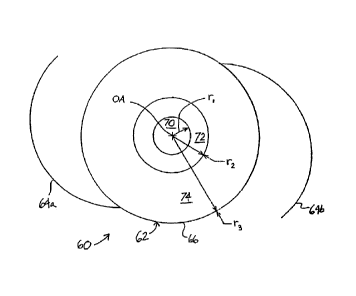
corrected. For example, many people are near-sighted because the axial length
of their eyes are
"too long" (myopia). As a result, the sharp image of an object is generated
not on the retina, but
in front of or before the retina. Hyperopia is a condition where the error of
refraction causes rays
of light to be brought to a focus behind the retina. This happens because the
axial length is "too
short". This condition is commonly referred to as far-sightedness. Another
refractive malady is
astigmatism resulting from a refractive surface with unequal curvatures in two
meridians.. The
different curvatures cause different refractive powers, spreading light in
front and in back of the
retina.
[0006] Other "higher order" maladies of 'interest for vision correction
include coma and
spherical aberration. Coma exists when an asymmetry in the optical system
causes unequal
optical path lengths in a preferred direction. For example, the image of an
off-axis point object
takes on a comet-like shape. For symmetrical systems, spherical aberration
exists when rays at
different radial heights from the optical axis focus at different axial
locations near the retina.
Whereas coma exists only in asymmetric systems, spherical aberration can exist
in both
symmetric and asymmetric systems. Other, even higher order, aberrations exist.
However,
studies have show that spherical aberration is one of the strongest higher
order aberrations in the
human visual system. Thus the retinal image may be improved if the spherical
aberration is
corrected according to known techniques.
. . =
[Oin] Studies have 'also shown that there Is a balante between the positive
spherical.
. . . = .
aberration Of the Carnet ind the iegittiVe berr. ation of the cry..
lens younger
. .
. . . = = = = = = = = .
= =.= ... = = .. . .
'eybg: As one grows 'older, the spherical 'aberration Of the.crOalline
lensbecennet'thore positiVe,
increasing the overall spherical aberration and reducing the image quality at
the retina.
[0008] An intraocular lens (IOL) is commonly used to replace the natural lens
of a
human eye when warranted by medical conditions such as cataracts. In cataract
surgery, the
surgeon removes the natural crystalline. lens from the capsular bag .or
posterior capsule .4nd
replaces it with an 10L. 10Ls may also be implanted in an eye (e.g., in the
anterior chamber)
with no cataract to supplement the refractive power of the natural crystalline
lens, correcting
large refractive errors.
[0009] The majority of ophthalmic lenses including 10Ls are monofocal, or
fixed focal
length, lenses that primarily correct refractive error. Most monofocal IOLs
are designed with
2
CA 02787997 2012-07-24
spherical anterior and posterior surfaces. The spherical surfaces of the
typically positive power
IOLs cause positive Spherical aberration, inter alia. Thus, replacement of the
crystalline lens
with a typical monofocal IOL leaves the eye with positive spherical
aberration. In real eyes with
complex corneal aberrations, the eye following cataract surgery is left a with
finite number of
complex lower and higher order aberrations, limiting the image quality on the
retina.
= [0010] Some examples of attempts to measure higher order aberrations of
the eye as an
optical system in order= to design an optical lens include U.S. Pat. No.
5,062,702 to Bille, et al.,
= U.S. patent No. 5,050,981 to Roffman, U.S. Pat No. 5,777,719 to Williams,
et al., and U.S.
patent No. 6,224,211 to Gordon.
[0011] A typical approach for improving the vision of a patient has been to
first obtain
measurements of the eye that relate to the topography of the anterior surface
of the cornea.
Specifically, the topography measurements yield a mathematical description of
the anterior
surface of the cornea. This corneal surface is placed in a theoretical model
of the patient's eye
with an IOL replacing the crystalline lens. Ray-tracing techniques are
employed to fird the IOL
design which corrects for the spherical aberration of the cornea. Ideally, if
implanted with this
custom 10L, the patient's vision will improve.
[0012] Recently, Pharmacia Corp. (Groningen, Netherlands) introduced a
posterior
capsule intraocular lens having the trade name TECNIS (Z9000) brand of
Silicone IOL. The
TECNIS lens has a prolate anterior surface, which is intended to reduce
spherical aberrations of
. . . . . .
the cornea.. This = lens may be designed .using methods described in U.. S.
Patent Number
6,609,793 and PCT publication W0.01/80424, both'to /4 or rb y The methods
in these
publications involve 'Characterizing:aberrant cOrileal sulfates as 'linear
conibinationg Of =Zeitike = =
polynomials, and then modeling or selecting an intraocular lens which, in
combination with a
characteristic corneal surface, reduces the optical aberrations ocular system.
The lenses resulting
from these methods may be continuous aspherical surfaces across the entire
optical zone and
may be, used to reduce spherical aberrations =of the eye by introducing
negative spherical
=
aberration to counter the typically positive spherical aberration of the
cornea. In these lenses,
there may be a single base curve on which the aspheric surface is
superimposed. As reported by
J. T. Holliday, et al., "A New Intraocular Lens Designed to Reduce Spherical
Aberration of
Pseudophalcic Eyes," Journal of Refractive Surgery 2002, 18:683-691, the
Technics IOL has
been found to be to improve visual contrast sensitivity at a frequency up to
18 cycles/degree.
3
CA 02787997 2012-07-24
[0013] The 'TECNIS brand of lens generally requires precise positioning in the
capsular
bag to provide improved optical quality over a spherical IOL (c.f.,
"Prospective Randomized
Trial of an Anterior Surface Modified Prolate Intraocular Lens," Journal of
Refractive sugery,
Vo. 18, Nov/Dec 2002). Slight errors in decentration (radial translation) or
tilt (axial rotation)
greatly reduces the effectiveness of the lens, especially in low-light
conditions, thus making the
task of the surgeon more difficult. Furthermore, shrinkage of the capsular bag
or other post-
implantation anatomical changes can affect the alignment or tilt of the lens
along the eye's
optical axis. It is believed that the "typical" magnitude of decentration
resulting from the
implantation of an intraocular lens in an average case, and factoring in post-
imiilantation
movement, is less than about 1.0 mm, and usually less than about 0.5 mm. Most
doctors agree
that decentration of an IOL greater than about 0.15 to approximately 0.4 min
is clinically
relevant (i.e., noticeably affects the performance of the optical
system,,according to those skilled
in the art). Similarly, the "typical" magnitude of tilt resulting from the
implantation of an
intraocular lens in an average case, and factoring in post-implantation
movement, is less than
about 10 degrees, and usually less than about 5 degrees. Therefore, in
practice, the benefits of
the 'TECNIS brand of lens may be offset by its apparent drawbacks in the real
world.
[0014] In view of the above, there remains a need for an intraocular lens that
corrects for
spherical aberrations in a variety of lighting conditions and is less
sensitive to non-optimal states
such as decentration and tilt of the IOL.
= Satan:tan, of the Iffireniicin
= . . . .
: 100111 The prnsent inveriticiri provides a multhzonal trionofocal
'ophthalmic lens that is
less sensitive to its disposition in the eye by reducing aberrations,
including the spherical
aberration, over a range of decentration. The monofocal ophthalmic lenses of
the present
invention may also be configured to perform well across eyes with different
corneal aberrations
(e.g., different. asphericities).
. .
[0016] In one aspect of the invention, a multi-zonal monofocal opthalmic lens
comprises
an inner zone, an intermediate zone, and an outer zone. The inner zone has a
first optical power.
The intermediate zone surrounds the inner zone and has a second optical power
that is different
from the first power by a magnitude that is less than at least about 0.75
Diopter. The outer zone
surrounds the intermediate zone and has a third optical power different from
the second optical
4
CA 02787997 2012-07-24
power. in certain embodiments, the third optical power is equal to the first
optical power. The
ophthalmic lens may comprise between 3 and 7 total zones, but favorably
comprises. between 3
=
and 5 total zones. However, ophthalmic lenses with more than seven total zones
are consistent
with embodiments of the invention.
[0017] In another aspect of the invention, a multi-zonal monofocal intraocular
lens has an
optic with a plurality of concentric optical zones centered on the optical
axis. The zones are
adapted to focus incoming light rays to form the image from one object. The
intraocular lens
optic includes an inner zone overlapping the optical axis of the lens that
provides an image when
the intraocular lens is centered on the optical axis of the human eye. A first
surrounding zone
concentric about the inner zone is adapted to compensate for optical
aberrations resulting from
implanted intraocular lens decentration of greater than at least about 0.1 mm.
[0018] The first surrounding zone may be configured to compensate for optical
aberrations resulting from implanted intraocular lens decentration of greater
than at least about
0.1 mm. The first surrounding zone may also compensate for optical aberrations
resulting from
implanted intraocular lens tilt of greater than at least about 1 degree. The
power of the first
surrounding zone preferably differs from the power of the inner zone by a
magnitude that is less
than or equal to at least about 0.75 Diopter. In an exemplary embodiment, the
inner zone
comprises a spherical surface and the first surrounding zone comprises an
aspherical surface.
[0019] Another aspect of the invention includes a method of designing multi-
zonal
=monofciCal =opthalmic 'lent. The Method comprises' providing an *optical
model of .the human eye. = . .
= The. Method farther comprise = an 'optical .niodei of n' lens comprising
an irtnerc- zone, an
= :interin¨ediate Zone, an= ou=ter zone; and zonal design parameters:
The method also comprises= =
adjusting the zonal design parameters based on an image output parameter for
one or more non-
optimal states of the lens.
[0020] The method may further include testing the intraocular lens over a wide
range of
clinically relevant corneal surface variations and dispositions. of optical
elements in the eye's.
optical system using ray-trace analysis techniques. Furthermore, the method
may be repeated to
modify zonal parameters and achieve a better average optical performance.
Examples of
conditions of asymmetry that the lens will correct include decentration, tilt,
and corneal
aberrations.
[0021] The invention, together with additional features and advantages
thereof, may best
=
CA 02787997 2012-07-24
be understood by reference to the following description taken in connection
with the
accompanying illustrative drawings in which like parts bear like reference
numerals.
Brief Description of the Drawings
[0022] Figure 1 is a schematic vertical cross-section of the human eye in a
bright light
environment and showing a pair of light rays passing through the optical
system of the cornea
and an implanted intraocular lens of the prior art to focus on the retina.
[0023] Figure 2 is a schematic vertical cross-section of the human eye in a
low light
environment and showing a pair of light rays passing through the optical
system of the cornea
and the peripheral regions of an implanted intraocular lens of the prior art
to focus in front of the
retina.
[0024] Figure 3 is a schematic vertical cross-section of the human eye in a
bright light
environment and showing a pair of light rays passing through the optical
system of the cornea
and a decentered implanted intraocular lens of the prior art to focus on the
retina.
[0025] Figure 4 is a schematic vertical cross-section of the human eye in a
medium light
environment and showing a pair of light rays passing through the optical
system of the cornea
and a decentered implanted intraocular lens of the prior art to focus in front
of the retina.
[0026] Figures 5A and 58 are schematic plan and side views of a monofocal
intraocular
lens of the present invention illustrating concentric zones about an optical
axis.
.== =
. j0027] Figures 64 and 6B show .simulated modulation transfer functions
for an ispheric;
. .
= 'spherical and multi-zonal monofocal IOLs at a 5mm pupil diameter With no
decentration"ind 0.5 =
. . . . . = = = . = =
. . . =
.inm deceniration, respectively:. = = .= - = = == = = = . = =
[0028] Figure 7 show simulated aspheric, spherical, and multi-zonal monofocal
TOL
MTF curves at a 5 mm pupil diameter representing the respective average MTFs
over 100 eyes
varying in corneal aberrations, IOL decentration and tilt, and small pupil
size changes.
. . .. =
Detailed Description
[0029] The present invention encompasses an intraocular lens (I0L) design that
reduces sensitivity to decentration within the eye while maintaining superior
Module Transfer
Function (MTF) performance for large pupils. The MTF is a measure of visual
performance
that can be plotted on a non-dimensional scale from a minimum of 0.0 to a
maximum of 1.0
6
CA 02787997 2012-07-24
across a range of spatial frequencies in units of cycles per mm. The MIF is a
measure of the
efficiency of "transferring" the contrast of an object into an image. The
spatial frequency is
inversely proportional to the size of the object. Thus, small objects at the
limit of visual
resolution have high spatial frequencies than larger objects. The IOL
described herein*
comprises a multi-zonal monofocal lens in which the anterior lens surface,
posterior lens
surface, or both comprises a plurality of zones that operate together on an
incident wavefront
to produce a corrected ocular image. The different zones of the IOL of the
present invention,
as described in greater detail below herein, generally have different mean
spherical curvatures
and/or Diopter powers, but the Diopter power differences between zones are far
less than the
typical 2 Diopter to 4 Diopter. design differences associated with multi-focal
10Ls. In certain
embodiments, the maximum Diopter power difference= between any two zones is
less than at
least about 0.75 D, advantageously less than about 0.65 D.
[0030] As used herein, the term "monofocal lens" is considered to be a lens in
which
light entering the lens from a distant point source is focused to
substantially a single r oint. In
the case of a multi-zonal monofocal lens, light from a distant point source
entering the lens
zones substantially fall within the range of the depth-of-focus of a spherical
lens having an
equivalent focal length.
[0031] As used herein in reference to the zones of a multi-zonal monofocal
lens, the
terms "optical power" and "Diopter power" refer to the effective optical or
Diopter power of a
. = . .= .
.zone Wheri.the lens is park of an ocularlens system such as, for example, a
cornea, a Multi- =
zonal monofocal ,=10L, = a = retina, and the material surrounding =these
'oniporients. This. = = =
õ .
. .
_definition may...include the effects ofthe=vergence or angle of light rays
intersecting the IOL = = =
surface caused by the power of the cornea. This may include the total vergence
from all
optical surfaces in front of the multi-zonal monofocal IOL. In certain
instances, an algorithm
for calculating the Diopter power may begin with a ray-tracing a model of the
human eye
incorporating a multi-zonal monofocal 10L. At a particular radial location on
the IOL surface,
= Snell's law may be applied to calculate the angle of the light ray
following the refraction. The
optical path length of the distance between a point on the surface and the
optical axis (axis of
symmetry) may be used to define the local radius of curvature of the local
wavefront. Using
such an approach, the Diopter power is equal to the difference in indicies of
refraction divided
by this local radius of curvature.
7
CA 02787997 2012-07-24
[0032] IOLs of the present invention are designed to outperform certain IOLs
of the
prior art in low or moderate light situations over a larger range of implant
positions. In
practice, clinicians recognize that in the average case intraocular lenses
implanted in the
posterior capsule end up decentered from the optical axis of the host eye by
between about
0.15-0.4 mm. Sometimes the decentration is greater as a result of poor implant
technique or
non-axisymmetric forces imparted by the host eye. Indeed, decentration of more
than 0.5 mm,
and sometimes up to 1.0 mm is experienced. IOLs of the present invention are
specifically
designed to exhibit superior performance in comparison to the prior art IOLs
when dec. entered
by at least about 0.15 mm and in particular in low or moderate light
conditions. In 'certain
embodiments, IOLs of the present invention are designed to exhibit superior
performance in
comparison to prior art IOLs when decentered by greater than about 0.5 mm or
greater than
about 1.0 mm. The amount of decentering to be accommodated depends upon design
constraints such as, for example, the accuracy of the surgical method to be
used for implanting
the IOL. Since the multi-zonal monofocal IOLs provide improved performance for
decentered
conditions, it is anticipated that patients will generally experience greater
satisfaction with a
multi-zonal monofocal IOL than with other prior art IOLs.
[0033] Figure 1 is a schematic vertical cross-section through a human eye 20
having
an IOL 22 of the prior art implanted therein. The optical system of the eye 20
includes an
outer cornea 24, a pupil 26 defined by an orifice of an iris 28, the IOL 22,
and a retina 30
. . = .
formed on the posterior inner surface of the ocular 'globe 32 In the present
application, the , =
. .
'terms anterior and Posterior ate used in their touveptional serige;
'aiitetior refers to the. front
= =
-side a the eye .Closer to .the cornea, whileposterior refers to the fear side
closer to the retina. -= '
The eye defines a natural optical axis OA. The drawing shows the eye 20 in a
bright light
environment with the iris 28 constricted resulting in a relatively small pupil
26.
[0034] The exemplary IOL 22 is adapted to be centered along the optical axis
OA and
within a capsular bag (not shown) just posterior to the iris 28.. For this
purpose, the .IOL 22
' may be provided with haptics or fixation members 34. An optic of the IOL
22 is defined by an
anterior face 36 and posterior face 38. The optic may take a variety of
configurations known
in the art, such as the convex-convex configuration illustrated in Figure 5B.
It should be
understood that the present invention is not limited to posterior capsule-
implanted IOLs.
[0035] A pair of light rays 40 pass through cornea 24, pupil 26, the IOL 22.
The rays
8
CA 02787997 2012-07-24
'' Bien" foe¨ us on the retina 30 along the optical axis OA. In the bright
light environment
shown, the light rays=40 pass through the mid-portion of the lens optic. The
intraocular lenses
of the prior art are relatively effective in focusing such light rays at a
point on the retina 30
along the optical axis OA.
[0036] Figure 2 shows the eye 20 having the IOL 22 therein in a low light
environment. In such situations, the iris 28 opens up creating a relatively
large pupil 26 and
= permitting more light to strike the IOL 22. A pair of light rays 42
passing through the
= peripheral regions of the pupil 26 may be incorrectly refracted by the
peripheral regions of the
optic of the IOL 22 in the manner shown. That is, the light rays 42 focus on a
spot 44 along
the optical axis OA that is in front of the retina 30 by a distance 46. Such
refraction is termed
positive spherical aberration because the light rays 42 focus in front of the
retina 30. A
negative spherical aberration focuses light rays at the imaginary point along
the optical axis
OA behind the retina 30. Such aberrations can also occur in an eye with the
natural lens still
in place. For example, the crystalline lens in the aging eye may not refract
light1 properly
under low light environments. The practical result of such a condition may be
a lossin image
quality.
[0037] Figure 3 illustrates the human eye 20 in a bright light environment
such as
shown in Figure 1. The IOL 22 centered along the optical axis OA is again
shown in solid
line, but is also shown in dashed line 22' representing a condition of
decentration. As
Mentioned above,. decentration involves a radial translation of the
intraocular lens from a
centered configuration On the natural 'Optical axis OA; = Thd light rays 40
pass tfircingh. the
= = , . = = =.= =. =. = . =
: cornea. 24 and relatively -small pupil 26;.and are refracted through' the
central region of the
decentered intraocular lens optic 22'. That is, despite the undesirable
decentration, the optic
22' performs well in bright light environments because light does not strike
and refract through
its peripheral regions.
[0038] Figure 4 illustrates the eye 20 in a medium light environment, in which
the iris
= . = . .
28 is somewhat larger compared to the condition shown in Figure 3, but is not
fully expanded
as seen in the low light environment of Figure 2. Under such conditions, a
centered IOL 22
would likely perform adequately, but the decentered lens 22' will not. More
particularly, a
light ray 48 passing close to the iris 28 will strike and be incorrectly
refracted through a
peripheral region of the decentered optic 22' as shown. Intraocular lenses of
the prior art have
=
9
CA 02787997 2012-07-24
varying degrees of sensitivity to decentration, and the situation shown in
Figure 4 is for
illustration purposes only and does not represent any particular lens.
[0039] However, it is believed that certain lenses designed to correct for
spherical
aberration, such as the TECNIS brand of lens, are relatively sensitive to
small magnitudes of
decentration. Such lenses have a complex refractive surface that changes
relatively
continuously across whichever face it is formed (i.e., anterior or posterior).
This continuous
refractive surface provides a negative correction for the positive spherical
aberration on the
cornea, but when the Jens is decentered the closely calculated balance between
the two optical
devices may be lost. Indeed, other optical aberrations such as coma and
astigmatism inay be
created by the resulting mismatch.
[0040] Figures 5A and 5B schematically illustrate in plan and side views a
monofocal
IOL 60 of the present invention having an optic 62 and a pair of haptics or
fixation members
64a, 64b extending outward therefrom. The optic 62 has a generally circular
peripheral edge
66 and a plurality of concentric annular refractive bands or zones formed
thereon. The
peripheral edge 66 is desirably an axially oriented edge with thickness, as
seen in Figure 5B,
although curved or angled edge surfaces, or combinations thereof, are
possible. The optic 62
has an anterior face 68a and an opposite posterior face 68b separated by the
peripheral edge
66. It should be understood that the refractive zones can be formed on either
the anterior or
posterior face, or in some cases as a combination of both faces. A central and
inner zone. 70
. = = . = = .
. = . =
==
centered on the optical axis .CiA extends =outward to a:radius of rj, at least
one intentediate
zone 72 surrounds the inner Zone 70 and extend outward to a radius of and an
outer zone
= . . . e = ===
74 iurroutids the interniediate 'zdne 72 and'exteiids therefrom tddie Outer
PeriPhery. 66 of
optic 62 and a radius of r3. Desirably, r1 is between about 1-1.5 nun, r2 is
between about 1.5-
2.2 mm, and r3 is about 3 mm. More desirably, ri is about 1.4 mm and r2. is
about 2.0 mm. In
certain instances, it may be desirable that 1.3 is greater than 3 mm, for
instance in order to
. preclude undesired edge effects.. . === = =
. . =
=
[0041) The inner zone 70, intermediate zone 72, and outer zone 74 may have
surfaces
that are either spherical or aspherical in shape. The intermediate zone 72 may
comprise a
combination of annular zones, although a single annular zone is generally
desirable. In certain
embodiments, the inner zone 70 is spherical, the intermediate zone 72 is
aspherical, and the
outer zone 74 is also aspherical.
CA 02787997 2012-07-24
[0042] The power of the inner zone 70 dominates the visual performance of the
eye
when the pupil is small, such as in bright daylight situations. The
intermediate zone 72 is at
least designed to help correct aberrations of the IOL when it is decentered,
tilted, or otherwise
in a non-optimal state. The power of intermediate zone 72 is extremely close
to that of the
inner zone 70. The outer zone 74 May be aspherical and designed to minimize
the spherical
aberrations natural to spherical monofocal IOLs.
[0043] Preferably, the intermediate zone 72 has a correction power that is
less than the
correction power of the inner zone 70. When a prior art IOL is decentered (Fig
4), peripheral
light is too strongly refracted and focuses in front of the retina. However,
the intermediate
zone 72 of the multi-zonal monofocal IOL 60 is used to reduce surface power,
redirecting the
light ray 48 to the focal point on the retina. The intermediate zone 72 may
also provide
correction in cases of tilting of the lens within the typical range of at
least about 1 to 10
degrees, depending upon design constraints such as, for example, the accuracy
of the surgical
method to be used for implanting the IOL.
[0044] The IOL 60 is considered to be a monofocal lens because the relative
refractive
powers of the zones 70, 72, and 74 are close to one another and within the
range of the depth-
of-focus of typical spherical monofocal IOLs. In this context, a "monofocal"
lens is one in
which discrete adjacent regions or zones have a maximum difference in
refractive power of
less than at least, about 0.75 Diopter. The refractive power of any one zone
may be interpreted
. = = , . . . = =:
.
as the mean power within that zOne. .It should also be understood that
discrete adjacent zones
. .
does not necessarily. mean that there .is sharp. physical transition
=therebetween,:. rather the
. . = . .
= iriaritifactiiiing. p.fOcess. be..d6signed to = e n er 1 y.
provide = a sthooth traniftiOri: between
adjacent zones.
[0045] The IOL 60 may be fabricated from materials used in the art, such as
silicon,
acrylic, or Polymethylmethacrylate (PMMA), or any other material that is
suitable for use in or
= on a human eye. Materials may also. be selected so .as to provide a
desired optical
performance. For instance, the refractive index is known to vary with
different materials and
may, therefore, be used as a design parameter for attaining a desired optical
performance or
affect from the IOL 60.
[0046] The IOL 60 may also be used in conjunction with other optical devices
such as
diffractive optical elements (DOE). For example, the anterior lens surface of
the IOL 60 may
11
CA 02787997 2013-04-03
comprise a multi-zonal surface and the posterior lens surface may contain a
DOE such as a
diffractive grating, or visa versa. Alternatively, the multi-zonal surface
itself may comprise a
DOE such as a diffractive grating. The DOE may also be used, for example, to
correct for
chromatic aberrations or to improve the performance of the IOL 60 when
displaced film the
optimal position (e.g., centered and normal to the optical axis). In certain
embodiments, the
DOE is disposed over only a portion of the one of the IOL surfaces. For
example, the DOE
may be disposed OVCT the intermediate zone 72 and used as an additional
parameter for
improving the performance of the IOL 60.
[0047] The IOL 60 may be designed to have a nominal optical power suited for
the
particular environment in which it is to be used. It is anticipated that the
nominal optical
power of the IOL 60 will generally be within a range of about -20 Diopters to
at least about
+35 Diopters. Desirably, the optical power of the IOL 60 is between about 10
Diopters to at
least about 30 Diopter. In certain applications, the optical power of the IOL
60 is
approximately 20 Diopters, which is a typical optical power for the natural
crystalline lens in a
human eye.
[0048] Under low light environments, such as night-time, the human eye has a
larger
pupil (about 4.5-6 mm in diameter) and hence has a large spherical aberration
(SA) that blurs the
image. Clinically, the large-pupil eye is reported to have a lower contrast
sensitivity and
sometimes lower visual acuity. The TECNISTm brand of lens has been reported to
perform better
, .
than spheiicat.I0Ls :in low light environments as judged by visitel contrast
sensitivity and visual
acnity.. According tosimulations, however; this isPherical design 1i
:sensitive to -deCeriiration. A
=
= 'fraction of a Millimeter decentration of such IOLs'froth the optical.
axis may dratifatitally break' =
the balance of SA between IOL and cornea, and thus seriously degrade the eye's
vision.
[00491 The inventors have discovered that spherical aberration can be reduced
for both
on-design and off-design conditions by forming a lens surface to have a multi-
zonal structure,
with each zone having different surface parameters, for example, the base
radius. of curvature. In
contrast with the prior art single continuous aspheric surface, such as the
TECNIS brand of lens
described above, the surface sag of the IOL 60 (i.e. multi-zonal surface
contour) may be
determined using an equation that changes across the lens. In accordance with
an exemplary
embodiment of the present invention, the surface sag at any radius from the
optical axis for an ith
zone is given by the following equation:
12
=
CA 02787997 2013-04-03
C * r2
Sag=+ tBu*(r ¨021
1+41 ¨(1+KI)*C12*r2 J-0 - J-1
where C.i, Kb and n are the base radius of curvature, the asphericity
constant, and the
height of the ith zonal surface. Further, the Bjs and Tjs are optional
boundary parameters that
can be used to connect the zonal surfaces smoothly. The variable M is an
integer that determines
how smoothly one zone transitions to another. This work makes use of a
published finite eye
model to represent the "nominar eye for IOL design (see, Liou H.L. and Brennan
N.A.,.
"Anatomically Accurate, Finite Model Eye for Optical Modeling, J Opt Soc Am A,
1997;
14:1684-1695).
[0050] For posterior chamber IOL design, the asphericity constant K1 in the
inner zone
70 (Figure SA) is preferably zero (i.e., the inner zone 70 comprises a
4pherical surface). The
base radius of curvature Cl in the inner zone 70 is considered to be the base
surface power of the
lens. There are preferably at least three zones (i 3) to achieve enhanced
performance for a 6
mm diameter pupil size. A preferred range of the number of zones is between at
least about 3-7,
more preferably between 3-5; however, larger numbers of zones may be used of
particular design
conditions. The parameters in the outlying zones can be optimally determined
such that each
zonal surface refracts more of the light rays in that particular zone to the
focus set by the inner
zone. This process can, be achieved by the .aid of .a cummercial optical ray
tracing design
softwareoutch._as ZEMAXTm optical (lesign .program from Zi1MArm Development
Corporation
(4901 Morena Blvd. Suite.207, San Diego, CA,.92117-7320).
[0051] In general', the base curves in at least two zones are different
(preferably the inner
and intermediate zones), though all zones may have different base curves.
Desirably, the
anterior surface has three zones, each having a different base radius of
curvature. The posterior
surface is a one zone spherical surface.
= [0052] Table 1 provides an example of a multi-zonal monofocal 101,
consistent With the
present invention. The values of the parameters given below are for an IOL
with an overall
Diopter power of 20 having 3 zones (i = 3) on the anterior surface and one
zone on the posterior
(i = 1).
13
CA 02787997 2012-07-24
Table I: Surface parameters of a 20D multi-zonal structured IOL
Anterior surface Symbol i = 1 i = 2 . i = 3
parameter =
Zonal outer radial ri (mm) 1.414 2.000 3.000
boundary, mm
Zonal curvature of - 0.08614900000
0.0751110000000 0.05055500000000
radius, 1/mm (1/nun)
Zonal asphericity 0.00000000000000 r -1.5931120000000 .8.90504900000000
M=3 1310 0.00163052185449 0.01542174622418 0.11151991935001
1311 -0.0024465216312 -0.0241315485668 -0.0611825408097
B12 0.00122363035200 0.08421200000000 0.00963200000000
Bj3 -0.0002040000000 -0.1293190000000 0.00399800000000
Ti) 0.00000000000000 .02774300000000 -0.0571790000000
Ti7 -0.0004750000000 -0.1375720000000 0.13027200000000
'I'D 0.00007700000000 0.23032800000000 -0.0800460000000
,Posterinr surface . = = ' ==== .
RiamPier == =
=ZtinEil outer radial'. *. ri(mm). = = 3.000 = = == == =,
= . = =
Zonal curvature of Ci 0.0636027120000
radius, 1/mm (1/mm)
Zonal asphericity KJ 0.00000000000000
= . =
M=0 N/A
Notes: 1. IOL refractive index at 35 is 1.47;
2. IOL central thickness is 0.977 nun.
3. IOL nominal base power = 20D
14
CA 02787997 2012-07-24
[0053] Figures 6A and 6B illustrate the IOL performance the multi-zonal
monofocal lens
shown in Table 1 in terms of the simulated modulation transfer functions as
compared to both a
=
spherical lens and an aspheric lens (the TECNIS brand of lens). These
simulated results are
based on a 5 mm pupil diameter with no decentration (Figure 6A) and 0.5 mm
decentration
(Figure 68). Figure 6A illustrates 'the performance for each type of lens when
the lenses are
precisely centered within the eye. In Figure 6B, the performance of each type
of lens is
illustrated when the lens is decentered from the optical axis of the eye by
0.5 mm, a condition
that is not uncommon under realistic conditions.
[0054] In comparing Figure 6B to Figure 6A, it can be seen that with
decentration, both
the aspheric and multi-zonal monofocal designs suffer a large loss in image
quality (e.g., MTF).
However, the multi-zonal loss is less compared to the aspheric design. Observe
in Figure 6A
that the aspheric and multi-zonal MTFs are significantly higher compared to
the standard
spherical surface design. The price paid for the significant enhancement of
image quality is the
sensitivity to non-nominal conditions (e.g., decentration) shown in Figure 6B.
Holever, some
improvement in the non-nominal condition can be achieved by this novel use of
zones in the
design of an improved monofocal IOL. The price paid for the reduction in non-
nominal
sensitivity is the slightly lower multi-zonal design MI? compared to the
aspheric MTF shown in
Figure 6A. Never-the-less, the multi-zonal MTF remains significantly improved
compared to
the spherical design MTF. =.
. .
. = 100551 Figure' '7 illustrates the results of a=Monte Carlo simulation
in the form of plots of
the average MTF performance for spherical, .aspheiic, and.multi-
zonal,inonoloc¨ JOLs based on
. .
over i00 different eyes. and'under:v.arYing conditioni of Corneal
aberration's, Ioi; decentration; ==
and IOL tilt. The simulation was conducted using a 5 mm nominal pupil
diameter. The results
compare the average performance of the various types of lenses under
simulated, real-world
conditions.
[0056] In clinical practice, many non-nominal conditions exist. These include
corneas
with different aberrations, different amounts of IOL tilt and decentration,
and different pupil
sizes for a nominal lighting condition. Other conditions may apply in more
unique
circumstances. Randomly selected values of the above "conditions" were
se]ected, individual
MTFs calculated, and the average ivrrF tabulated. In effect, this procedure
simulates the general
clinical population and assesses the complex interaction of the IOL surface
design and
CA 02787997 2012-07-24
aberrations induced by the non-nominal conditions.
[0057] Figure 7 shows the results of such a "clinical simulation", comparing
the aspheric,
spherical, and multi-zonal designs. Figure 7 suggests that the aspheric design
will improve the
MTF at lower spatial frequencies compared to the spherical design. From the
patient's
perspective, objects will have a higher contrast and color will appear richer.
Figure 7 predicts
that the multi-zonal design will provide even more improvement over a wide
range of spatial
frequencies. The patient should experience both improved contrast and visual
acuity. The latter
is related to changes in MTF at about 100 cycles/mm. As expected, when
averaged over an
entire clinical population; the multi-zonal design provides more improvement
compated to an
aspheric design, even though the multi-zonal design is slightly lower in
performance in the
nominal condition (Figure 6a).
[0058] In certain embodiments, a method of designing a mniti-zonal monofocal
IOL
comprises providing an optical model of the human eye. The model may include a
corona, an
iris, the IOL 60, a retina, and any liquids, substances, or additional devices
between the these
components. The model may also include various system design parameters such
as the spacing
between components and refractive index values.
[0059] The method further comprises providing an optical model of a lens
comprising an
inner zone, an intermediate zone, an outer zone, and zonal design parameters
(e.g., the IOL 60).
The zonal design parameters for each of the.zones may include, but are not
limited to, á radius of
curvature, Surface polynomial coefficients, inner radius, outer radius,
refractive index, and pc$ = .
.. = =
*characteristics.' In certain embodiments, the model may inclucle additional
zones along with iheir.
dOrresponding paranieters: One of the ionlif design" paraMeter may. alSO
inehide the iturnber of= = -*
zones in the lens. The model may comprise the zones and zonal design
parameters for an
anterior surface of the lens, the posterior surface of the lens, or both
surfaces of the lens.
[0060] The method further comprises adjusting the zonal design parameters
based on an
image output parameter forone or more non-optimal states of the lens. Examples
of non-optimal
states include, but are not limited to, IOL decentration and tilt, and
different corneal aberrations
(e.g., different corneal asphericities). Examples of image output parameter
include, but are not
limited to, the Modulation Transfer Function, spot radius, and/or wavefront
error. Alternatively,
a plurality of output parameters may. be used for evaluation while adjusting
the zonal design
parameters.
16
CA 02787997 2012-07-24
[O061] With the IOL in a non-optimal state, zonal design parameters such as
the number
of zones and zone radii may be adjusted to correct any aberrant light rays
entering the system
=
entrance pupil. For example, in the case of IOL de,centration and a three-zone
lens, the first zone
radius and second zone radius are chosen such that the second zone falls
within the entrance
pupil. The zonal design parameters for the zones exposed by light entering the
system entrance
pupil may be adjusted to compensate for the aberrations produced by the non-
optimal state.
Preferably, the zonal design parameters are adjusted until the image output
parameter obtains an
optimized or threshold value.
[0062] The method may also include adjusting the zonal design parameters
and/or the .
other system design parameters of the optical model based on the image output
parameter for an
optimal state of the lens. Such an optimal state would preferably represent a
condition in which
the IOL is centered along the optic axis of the eye and normal thereto.
[0063] The method may be realized using optical design software that is
resides on a
computer or other processing device. The optical design software may be used
to numerically
ray-traces various sets of light rays through optical model and that evaluates
the image formed
on the retina. Recognizing that the modeled cornea has finite aberrations, the
design parameters
of the multi-zonal monofocal IOL may be adjusted to improve the quality of the
image formed
on the retina in terms of the image output parameter or in terms of a
plurality of image output
parameters. . , .
=.
[0004] The resulting lens. frOM this design may .produce slightly lower
retinal imago = .
quality when placed iri=the optimal State as compared to.the.optimal .design
in the optimal state.
. .
However,..such a.non:-optimal-= state design will still-allow 'a lens'to be
prodiked that provides = =
significantly better performance than that possible using spherical optics.
Thus, the non-optimal
state design provides superior performance over a greater range of non-optimal
conditions as
compared to the initial optimal-design.
[0065) In certain embodiments, additional non-optimal states are used. to
further adjust
the design parameters in order to provide a design that is suitable of a
particular condition or set
of conditions. The results using various non-optimal states may be used to
provide a lens suited
for a plurality of anticipated non-optimal states of an IOL within an eye or
certain population of
eyes having certain aberrations. For instance, the method may be used for
testing the lens over a
plurality of corneal surface variations and dispositions of optical elements
in the eye's optical
17
CA 02787997 2012-07-24
system using tolerance analyzing techniques. Additionally, all or part of the
method may be
repeated one or more times to modify zonal parameters and achieve a better
average optical
performance. Known algorithms, such as assigning weighting functions to the
various non-
optimal states, may be used to provide a lens with desired characteristics.
[0066) While embodiments of the invention have been disclosed for an IOL
suitable
providing enhanced performance under non-optimal conditions, such as when the
IOL is
decentered from the optical axis of the eye, those skilled in the art will
appreciate that
embodiments of the invention are suitable for other ocular devices such as
contact lenses and
corneal implants. For instance, the method of designing a multi-zonal
rnonofocal IOL inay be
adapted for improving the performance of contact lenses, which are known to
move to
different positions during use relative to the optical axis of the eye.
[0067] While "this invention has been described with respect to various
specific examples
and embodiments, it is to be understood that these are merely exemplary and
that the invention is
not limited thereto and that it can be variously practiced within the scope of
the following claims.
18