Note: Descriptions are shown in the official language in which they were submitted.
CA 02788139 2012-07-20
WO 2011/103219 PCT/US2011/025132
On and Off-Screen Gesture Combinations
BACKGROUND
[00011 One of the challenges that continues to face designers of devices
having user-engageable displays, such as touch displays, pertains to providing
enhanced functionality for users, without necessarily permanently manifesting
the
functionality as part of the "chrome" of a device's user interface. This is
so, not
only with devices having larger or multiple screens, but also in the context
of
devices having a smaller footprint, such as tablet PCs, hand-held devices,
smaller
multi-screen devices and the like.
SUMMARY
[00021 This Summary is provided to introduce a selection of concepts in a
simplified form that are further described below in the Detailed Description.
This
Summary is not intended to identify key features or essential features of the
claimed subject matter, nor is it intended to be used as an aid in determining
the
scope of the claimed subject matter.
[00031 Bezel gestures for touch displays are described. In at least some
embodiments, the bezel of a device is used to extend functionality that is
accessible
through the use of so-called bezel gestures. In at least some embodiments, off-
screen motion can be used, by virtue of the bezel, to create screen input
through a
bezel gesture. Bezel gestures can include single-finger bezel gestures,
multiple-
finger/same-hand bezel gestures, and/or multiple-finger, different-hand bezel
gestures.
BRIEF DESCRIPTION OF THE DRAWINGS
[00041 The detailed description is described with reference to the
accompanying figures. In the figures, the left-most digit(s) of a reference
number
identifies the figure in which the reference number first appears. The use of
the
same reference numbers in different instances in the description and the
figures
may indicate similar or identical items.
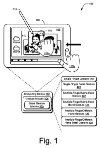
[00051 FIG. 1 is an illustration of an environment in an example
implementation in accordance with one or more embodiments.
1
CA 02788139 2012-07-20
WO 2011/103219 PCT/US2011/025132
[00061 FIG. 2 is an illustration of a system in an example implementation
showing FIG. 1 in greater detail.
[00071 FIG. 3 illustrates an example computing device in accordance with
one or more embodiments.
[00081 FIG. 4 is a flow diagram that describes the steps in a method in
accordance with one or more embodiments.
[00091 FIG. 5 is a flow diagram that describes the steps in a method in
accordance with one or more embodiments.
[00101 FIG. 6 illustrates an example computing device in accordance with
one or more embodiments.
[00111 FIG. 7 illustrates an example computing device in accordance with
one or more embodiments.
[00121 FIG. 8 illustrates an example computing device in accordance with
one or more embodiments.
[00131 FIG. 9 illustrates an example computing device in accordance with
one or more embodiments.
[00141 FIG. 10 is a flow diagram that describes the steps in a method in
accordance with one or more embodiments.
[00151 FIG. 11 is a flow diagram that describes the steps in a method in
accordance with one or more embodiments.
[00161 FIG. 12 illustrates an example computing device in accordance with
one or more embodiments.
[00171 FIG. 13 illustrates an example computing device in accordance with
one or more embodiments.
[00181 FIG. 14 illustrates an example computing device in accordance with
one or more embodiments.
[00191 FIG. 15 is a flow diagram that describes the steps in a method in
accordance with one or more embodiments.
[00201 FIG. 16 is a flow diagram that describes the steps in a method in
3o accordance with one or more embodiments.
2
CA 02788139 2012-07-20
WO 2011/103219 PCT/US2011/025132
[00211 FIG. 17 illustrates an example computing device in accordance with
one or more embodiments.
[00221 FIG. 18 is a flow diagram that describes the steps in a method in
accordance with one or more embodiments.
[00231 FIG. 19 illustrates an example computing device in accordance with
one or more embodiments.
[00241 FIG. 20 is a flow diagram that describes the steps in a method in
accordance with one or more embodiments.
[00251 FIG. 21 illustrates an example computing device in accordance with
one or more embodiments.
[00261 FIG. 22 illustrates an example computing device in accordance with
one or more embodiments.
[00271 FIG. 23 illustrates an example computing device in accordance with
one or more embodiments.
[00281 FIG. 24 illustrates an example computing device in accordance with
one or more embodiments.
[00291 FIG. 25 is a flow diagram that describes the steps in a method in
accordance with one or more embodiments.
[00301 FIG. 26 is a flow diagram that describes the steps in a method in
accordance with one or more embodiments.
[00311 FIG. 27 illustrates an example computing device in accordance with
one or more embodiments.
[00321 FIG. 28 illustrates an example computing device in accordance with
one or more embodiments.
[00331 FIG. 29 illustrates an example computing device in accordance with
one or more embodiments.
[00341 FIG. 30 is a flow diagram that describes the steps in a method in
accordance with one or more embodiments.
[00351 FIG. 31 is a flow diagram that describes the steps in a method in
3o accordance with one or more embodiments.
3
CA 02788139 2012-07-20
WO 2011/103219 PCT/US2011/025132
[00361 FIG. 32 is a flow diagram that describes the steps in a method in
accordance with one or more embodiments.
[00371 FIG. 33 illustrates an example computing device that can be utilized
to implement various embodiments described herein.
DETAILED DESCRIPTION
Overview
[00381 Bezel gestures for touch displays are described. In at least some
embodiments, the bezel of a device is used to extend functionality that is
accessible
through the use of so-called bezel gestures. In at least some embodiments, off-
screen motion can be used, by virtue of the bezel, to create screen input
through a
bezel gesture. Bezel gestures can include single-finger bezel gestures,
multiple-
finger/same-hand bezel gestures, and/or multiple-finger, different-hand bezel
gestures.
[00391 In the following discussion, a variety of different implementations are
described that involve bezel gestures, or gestures associated with bezel
gestures, to
initiate and/or implement functions on a computing device. In this way, a user
may
readily access enhanced functions of a computing device in an efficient and
intuitive manner.
[00401 In the following discussion, an example environment is first
described that is operable to employ the gesture techniques described herein.
Example illustrations of the gestures and procedures are then described, which
may
be employed in the example environment, as well as in other environments.
Accordingly, the example environment is not limited to performing the example
gestures and the gestures are not limited to implementation in the example
environment.
Example Environment
[00411 FIG. 1 is an illustration of an environment 100 in an example
implementation that is operable to employ bezel gestures and other techniques
described herein. The illustrated environment 100 includes an example of a
computing device 102 that may be configured in a variety of ways. For example,
the computing device 102 may be configured as a traditional computer (e.g., a
4
CA 02788139 2012-07-20
WO 2011/103219 PCT/US2011/025132
desktop personal computer, laptop computer, and so on), a mobile station, an
entertainment appliance, a set-top box communicatively coupled to a
television, a
wireless phone, a netbook, a game console, a handheld device, and so forth as
further described in relation to FIG. 2. Thus, the computing device 102 may
range
from full resource devices with substantial memory and processor resources
(e.g.,
personal computers, game consoles) to a low-resource device with limited
memory
and/or processing resources (e.g., traditional set-top boxes, hand-held game
consoles). The computing device 102 also includes software that causes the
computing device 102 to perform one or more operations as described below.
[00421 Computing device 102 includes a bezel 103 that forms part of the
device's housing. The bezel is made up of the frame structure adjacent the
device's
display, also referred to as display device 108 below. Computing device 102
includes a gesture module 104 and a bezel gesture module 105 that forms part
of
the gesture module 104. The gesture modules can be implemented in connection
with any suitable type of hardware, software, firmware or combination thereof.
In
at least some embodiments, the gesture modules are implemented in software
that
resides on some type of tangible, computer-readable medium examples of which
are provided below.
[00431 Gesture module 104 and bezel gesture module 105 are representative
of functionality that recognizes gestures and bezel gestures, respectively,
and
causes operations to be performed that correspond to the gestures. The
gestures
may be recognized by modules 104, 105 in a variety of different ways. For
example, the gesture module 104 may be configured to recognize a touch input,
such as a finger of a user's hand 106a as proximal to display device 108 of
the
computing device 102 using touchscreen functionality. In addition, bezel
gesture
module 105 can be configured to recognize a touch input, such as a finger of a
user's hand 106b, that initiates a gesture on or adjacent bezel 103 and
proceeds
onto display device 108. Any suitable technology can be utilized to sense an
input
on or adjacent bezel 103. For example, in at least some embodiments, the
digitizer
or sensing elements associated with display device 108 can extend underneath
bezel 103. In this instance, technologies such as capacitive field
technologies, as
5
CA 02788139 2012-07-20
WO 2011/103219 PCT/US2011/025132
well as others, can be utilized to sense the user's input on or adjacent to
the bezel
103.
[00441 Alternately or additionally, in embodiments in which display device
108 does not extend underneath bezel 103, but rather lies flush with the
bezel,
bezel gesture module 105 can detect the changing contact profile of the user's
finger as it emerges onto display device 108 from bezel 103. Alternately or
additionally, approaches that utilize the centroid of the user's touch profile
can be
utilized to detect a changing centroid contact profile that is suggestive of a
bezel
gesture. Further, techniques for fingerprint sensing can be employed.
Specifically,
1o if the sensing substrate is sensitive enough to determine ridges of the
finger or
fingers contacting the display, then the orientation of the finger(s) as well
as the
fact that the fingerprint is clipped by the bezel can be detected. Needless to
say,
any number of different techniques can be utilized to sense a user's input
relative to
the bezel 103. The touch input may also be recognized as including attributes
(e.g.,
movement, selection point, etc.) that are usable to differentiate the touch
input from
other touch inputs recognized by the gesture modules 104, 105. This
differentiation
may then serve as a basis to identify a gesture from the touch inputs and
consequently an operation that is to be performed based on identification of
the
gesture. This yields the general benefit that gestures that start from the
bezel and
enter onto the screen are, in general, distinguishable from other ostensibly
similar
gestures that access on-screen content, since there is no reason for users to
position
their fingers starting partially or fully off-screen if their intent is to
interact with
something on the screen. Hence, normal direct manipulative gestures, even for
objects near the screen boundaries, are still possible and do not interfere
with bezel
gestures and vice versa.
[00451 For example, a finger of the user's hand 106a is illustrated as
selecting 110 an image 112 displayed by the display device 108. Selection 110
of
the image 112 and subsequent movement of the finger of the user's hand 106a
may
be recognized by the gesture module 104. The gesture module 104 may then
identify this recognized movement as indicating a "drag and drop" operation to
change a location of the image 112 to a point in the display at which the
finger of
6
CA 02788139 2012-07-20
WO 2011/103219 PCT/US2011/025132
the user's hand 106a was lifted away from the display device 108. Thus,
recognition of the touch input that describes selection of the image, movement
of
the selection point to another location, and then lifting of the finger of the
user's
hand 106a may be used to identify a gesture (e.g., drag-and-drop gesture) that
is to
initiate the drag-and-drop operation.
[00461 A variety of different types of gestures may be recognized by the
gesture modules 104, 105 such as gestures that are recognized from a single
type of
input (e.g., touch gestures such as the previously described drag-and-drop
gesture)
as well as gestures involving multiple types of inputs. For example, modules
104,
105 can be utilized to recognize single-finger gestures and bezel gestures,
multiple-
finger/same-hand gestures and bezel gestures, and/or multiple-finger/different-
hand
gestures and bezel gestures.
[00471 For example, the computing device 102 may be configured to detect
and differentiate between a touch input (e.g., provided by one or more fingers
of
the user's hand 106a, 106b) and a stylus input (e.g., provided by a stylus
116). The
differentiation may be performed in a variety of ways, such as by detecting an
amount of the display device 108 that is contacted by the finger of the user's
hand
106 versus an amount of the display device 108 that is contacted by the stylus
116.
[00481 Thus, the gesture modules 104, 105 may support a variety of different
gesture techniques through recognition and leverage of a division between
stylus
and touch inputs, as well as different types of touch inputs.
[00491 Accordingly, the gesture modules 104, 105 may support a variety of
different gestures. Examples of gestures described herein include a single-
finger
gesture 118, a single-finger bezel gesture 120, a multiple-finger/same-hand
gesture
122, a multiple-finger/same-hand bezel gesture 124, a multiple-
finger/different
hand gesture 126, and a multiple-finger/different-hand bezel gesture 128. Each
of
these different types of bezel gestures is described below.
[00501 FIG. 2 illustrates an example system showing the gesture module 104
and bezel gesture module 105 of FIG. 1 as being implemented in an environment
where multiple devices are interconnected through a central computing device.
The
central computing device may be local to the multiple devices or may be
located
7
CA 02788139 2012-07-20
WO 2011/103219 PCT/US2011/025132
remotely from the multiple devices. In one embodiment, the central computing
device is a "cloud" server farm, which comprises one or more server computers
that
are connected to the multiple devices through a network or the Internet or
other
means.
[00511 In one embodiment, this interconnection architecture enables
functionality to be delivered across multiple devices to provide a common and
seamless experience to the user of the multiple devices. Each of the multiple
devices may have different physical requirements and capabilities, and the
central
computing device uses a platform to enable the delivery of an experience to
the
1o device that is both tailored to the device and yet common to all devices.
In one
embodiment, a "class" of target device is created and experiences are tailored
to the
generic class of devices. A class of device may be defined by physical
features or
usage or other common characteristics of the devices. For example, as
previously
described the computing device 102 may be configured in a variety of different
ways, such as for mobile 202, computer 204, and television 206 uses. Each of
these configurations has a generally corresponding screen size and thus the
computing device 102 may be configured as one of these device classes in this
example system 200. For instance, the computing device 102 may assume the
mobile 202 class of device which includes mobile telephones, music players,
game
devices, and so on. The computing device 102 may also assume a computer 204
class of device that includes personal computers, laptop computers, netbooks,
and
so on. The television 206 configuration includes configurations of device that
involve display in a casual environment, e.g., televisions, set-top boxes,
game
consoles, and so on. Thus, the techniques described herein are may be
supported
by these various configurations of the computing device 102 and are not
limited to
the specific examples described in the following sections.
[00521 Cloud 208 is illustrated as including a platform 210 for web services
212. The platform 210 abstracts underlying functionality of hardware (e.g.,
servers) and software resources of the cloud 208 and thus may act as a "cloud
operating system." For example, the platform 210 may abstract resources to
connect the computing device 102 with other computing devices. The platform
210
8
CA 02788139 2012-07-20
WO 2011/103219 PCT/US2011/025132
may also serve to abstract scaling of resources to provide a corresponding
level of
scale to encountered demand for the web services 212 that are implemented via
the
platform 210. A variety of other examples are also contemplated, such as load
balancing of servers in a server farm, protection against malicious parties
(e.g.,
spam, viruses, and other malware), and so on.
[00531 Thus, the cloud 208 is included as a part of the strategy that pertains
to software and hardware resources that are made available to the computing
device
102 via the Internet or other networks. For example, the gesture modules 104,
105
may be implemented in part on the computing device 102 as well as via a
platform
l0 210 that supports web services 212.
[00541 For example, the gesture techniques supported by the gesture
modules may be detected using touchscreen functionality in the mobile
configuration 202, track pad functionality of the computer 204 configuration,
detected by a camera as part of support of a natural user interface (NUI) that
does
not involve contact with a specific input device, and so on. Further,
performance of
the operations to detect and recognize the inputs to identify a particular
gesture may
be distributed throughout the system 200, such as by the computing device 102
and/or the web services 212 supported by the platform 210 of the cloud 208.
[00551 Generally, any of the functions described herein can be implemented
using software, firmware, hardware (e.g., fixed logic circuitry), manual
processing,
or a combination of these implementations. The terms "module,"
"functionality,"
and "logic" as used herein generally represent software, firmware, hardware,
or a
combination thereof. In the case of a software implementation, the module,
functionality, or logic represents program code that performs specified tasks
when
executed on a processor (e.g., CPU or CPUs). The program code can be stored in
one or more computer readable memory devices. The features of the gesture
techniques described below are platform-independent, meaning that the
techniques
may be implemented on a variety of commercial computing platforms having a
variety of processors.
9
CA 02788139 2012-07-20
WO 2011/103219 PCT/US2011/025132
[00561 In the discussion that follows, various sections describe example
bezel gestures and gestures associated with bezel gestures. A first section
entitled
"Use of Bezel as an Input Mechanism" describes embodiments in which a
computing device's bezel can be used as an input mechanism. Following this, a
section entitled "Using Off-Screen Motion to Create On-Screen Input" describes
how a motion away from a device's screen can be utilized, through gestures, to
create on-screen input. Next, a section entitled "Use of Multiple Fingers for
Gesturing" describes how multiple fingers can be utilized to provide gestural
input.
Following this section, a section entitled "Radial Menus" describes
embodiments in
1o which radial menus can be utilized to provide a robust collection of input
options.
Next, a section entitled "On and Off Screen Gestures and Combinations -
Page/Object Manipulation" describes various types of gestures and combinations
that can be utilized to manipulate pages and/or objects. Last, a section
entitled
"Example Device" describes aspects of an example device that can be utilized
to
implement one or more embodiments.
Use of Bezel as an Input Mechanism
[00571 In one or more embodiments, the bezel of a device can be utilized as
an input mechanism. For example, in instances in which the display device
extends
under the bezel, a user's finger or other input mechanism can be sensed when
it
hovers over or physically engages the bezel. Alternately or additionally, the
bezel
can include sensing mechanisms, such as infrared mechanisms as well as others,
that sense a user's finger or other input mechanism hovering over or
physically
engaging the bezel. Any combination of inputs relative to the bezel can be
used.
For example, to provide various inputs to the device, the bezel can be tapped
one or
more times, held, slid over, hovered over and/or any combination of these or
other
inputs.
[00581 As an example, consider the following. Many selection,
manipulation, and context menu activation schemes utilize a distinction
between a
device's background canvas and objects that appear on the canvas. Using the
bezel
3o as an input mechanism can provide a way to access a page in the background
canvas, even if the page itself is covered by many closely-spaced objects. For
CA 02788139 2012-07-20
WO 2011/103219 PCT/US2011/025132
example, tapping on the bezel may provide a mechanism to deselect all objects.
Holding on the bezel could be used to trigger a context menu on the page. As
an
example, consider FIG. 3 which illustrates an example environment 300 that
includes a computing device 302 having a bezel 303 and a display device 308.
In
this instance, a finger on user's hand 306a is tapping on bezel 303. By
tapping on
the bezel, the user's input is sensed and an associated functionality that is
mapped
to the input can be provided. In the above example, such functionality might
deselect all objects appearing on display device 308. In addition, input can
be
received at different locations on the bezel and can be mapped to different
to functionality. For example, input received on the right side of the bezel
might be
mapped to a first functionality; input received on the left side of the bezel
might be
mapped to a second functionality and so on. Furthermore, input received in
different regions of a bezel side might be mapped to different functionality
or to no
functionality at all depending on the orientation of the device and how the
user is
holding it. Some bezel edges may be left unassigned or may be insensitive to
touch-and-hold, so that inadvertent operations will not be triggered. Thus,
any one
particular side of the bezel might be utilized to receive input and,
accordingly map
that input to different functionality depending on what region of the bezel
receives
the input. It is to be appreciated and understood that input received via the
bezel
can be received independent of any input received via hardware input devices,
such
as buttons, track balls, and other instrumentalities that might be located on
an
associated device. Further, in at least some embodiments, input received via
the
bezel can be the only user input that is utilized to ascertain and access a
particular
functionality. For example, input received solely on the bezel can provide the
basis
by which device functionality can be accessed. Further, in some embodiments,
orientation sensors (e.g. accelerometers) may be used as an input to help
decide
which bezel edges are active. In some embodiments quick, intentional tap
remains
available, but only touch and hold is ignored to differentiate from simply
holding
the device with a finger that happens to be resting on the bezel.
11
CA 02788139 2012-07-20
WO 2011/103219 PCT/US2011/025132
[00591 Alternately or additionally, in at least some embodiments, a visual
affordance can be utilized to provide a hint or indication of accessible
functionality
associated with the bezel. Specifically, a visual affordance can be utilized
to
indicate functionality that is accessible by virtue of a bezel gesture. Any
suitable
type of visual affordance can be utilized. As an example, consider again FIG.
3.
There, a visual affordance in the form of a semi-transparent strip 304
provides an
indication that additional functionality can be accessed through utilization
of a
bezel gesture. The visual affordance can take any suitable form and can be
located
at any suitable location on display device 308. Furthermore, the visual
affordance
1o can be exposed in any suitable way. For example, in at least some
embodiments,
input received via the bezel can be used to expose or display the visual
affordance.
Specifically, in at least some embodiments, a "peek out" visual affordance can
be
presented responsive to detecting a hover over, or a physical engagement of
the
device's bezel. The "peek out" visual affordance can, in at least some
embodiments, be deselected by the user such that the "peek out" is hidden.
[00601 In this particular example, the additional functionality associated
with
semi-transparent strip 304 resides in the form of a so-called bezel menu which
is
accessible using a bezel gesture. Specifically, in one or more embodiments,
the
bezel menu can be accessed through a gesture in which a finger of user's hand
306b
touches the bezel and then moves across the bezel and onto the display device
308
in the direction of the illustrated arrow. This can allow the bezel menu to be
dropped down as will be described in more detail below.
[00611 Accordingly, various embodiments can use the bezel itself as an input
mechanism, as in the first example above. Alternately or additionally, various
other embodiments can use the bezel in connection with a visual affordance
that
provides a clue to the user that additional functionality can be accessed by
virtue of
a bezel gesture.
[00621 FIG. 4 is a flow diagram that describes steps in a method in
accordance with one or more embodiments. The method can be implemented in
connection with any suitable hardware, software, firmware, or combination
thereof.
12
CA 02788139 2012-07-20
WO 2011/103219 PCT/US2011/025132
In at least some embodiments, the method can be implemented in connection with
a
system such as those systems that are described above and below.
[00631 Step 400 receives an input associated with a bezel. Any suitable type
of input can be received, examples of which are provided above. Step 402
accesses
functionality associated with the received input. Any suitable type of
functionality
can be accessed. By virtue of providing a variety of different types of
recognizable
inputs (e.g., taps, tap combinations, tap/hold combinations, slides, etc), and
mapping those recognizable inputs to different types of functionalities, a
robust
collection of user input mechanisms can be provided.
[00641 FIG. 5 is a flow diagram that describes steps in a method in
accordance with one or more embodiments. The method can be implemented in
connection with any suitable hardware, software, firmware, or combination
thereof.
In at least some embodiments, the method can be implemented in connection with
a
system such as those systems that are described above and below.
[00651 Step 500 displays a visual affordance on a display device associated
with a computing device. Any suitable type of visual affordance can be
utilized, an
example of which is provided above. Step 502 receives a bezel gesture input
relative to the visual affordance. Any suitable type of bezel gesture input
can be
utilized. Step 504 accesses functionality associated with the received bezel
gesture
input. Any suitable type of functionality can be accessed, an example of which
is
provided above and described in more detail below.
[00661 Having considered examples in which the bezel can be used as an
input mechanism, consider now various embodiments that can utilize off-screen
or
off-display motion to create screen or display input.
Using Off-Screen Motion to Create On-Screen Input
[00671 In at least some embodiments, off-screen to on-screen motion (or vice
versa) can be utilized as a mechanism to expose a menu or to access some other
type of functionality. The off-screen motion or input can be provided, as
indicated
above, relative to the device's bezel. Any suitable type of bezel gesture
input can
3o be provided in order to effectuate the off-screen to on-screen motion. For
example,
bezel gestures or inputs can, by way of example and not limitation, start or
end on
13
CA 02788139 2012-07-20
WO 2011/103219 PCT/US2011/025132
the bezel, cross or recross the bezel, cross at different locations of the
bezel (e.g.,
the corners, or particular ranges of coordinates along a particular edge),
and/or
occur on one or more bezels associated with multiple screens (with the
possibility
of different semantics depending on the screen or edge thereof). Further,
bezel
inputs can include, by way of example and not limitation, a single-contact
drag
(finger or pen), two-contact drag (two fingers), and/or a hand-contact drag
(multiple fingers/whole hand/multiple or single fingers on different hands).
For
example, pinch gestures from off-screen space (i.e. originating on the bezel)
can be
utilized and mapped to different functionalities. For example, bezel gestures
with
multiple contacts entering from different edges of the screen can have
different
semantics. Specifically, two fingers entering from adjacent edges of the bezel
(i.e.
spanning a corner) might be mapped to a zoom out operation that zooms out on a
page to show an extended workspace or canvas. Two fingers entering from
opposite edges, with either one hand (if the screen is small enough), or two
hands
(one finger from each hand) can be mapped to a different functionality.
Multiple
fingers entering on one edge of the bezel and one finger entering from an
adjacent
or opposite edge of the bezel might be mapped to a different functionality.
Additionally, multiple fingers entering from two or more edges can further be
mapped to additional functionality.
[00681 As another example, consider FIG. 6. There, device 602 includes a
bezel 603 and a visual affordance 604 that is rendered on display device 608.
As
noted above, visual affordance 604, in the form of a semi-transparent strip,
can be
utilized to provide a hint or indication of accessible functionality, in this
case a
bezel menu, associated with the bezel.
[00691 In one or more embodiments, the bezel menu can be accessed
through a bezel gesture in which a finger of user's hand 606 touches the bezel
and
then moves across the bezel and onto the display device 608 in the direction
of the
illustrated arrow. This can allow bezel menu 610 to be dropped down at which
time it can become fully opaque.
14
CA 02788139 2012-07-20
WO 2011/103219 PCT/US2011/025132
[00701 In the illustrated and described embodiment, bezel menu 610
includes multiple selectable icons or slots 612, 614, 616, 618, and 620. Each
of the
icons or slots is associated with a different functionality such as, for
example, paint
functionality, pen functionality, note functionality, object creation, object
editing,
and the like. It is to be appreciated and understood, that any type of
functionality
can be associated with the icons or slots.
[00711 In the illustrated and described environment, bezel menu 610 can
enable a user to access and activate commands, tools, and objects. The bezel
menu
can be configured to respond to both touch input and pen input. Alternately or
1o additionally, the bezel menu can be configured to respond only to touch
input.
[00721 In at least some embodiments, different gestural modes can be
utilized to access functionality associated with the bezel menu 610. For
example,
one gestural mode can be a novice mode, and another gestural mode can be an
expert mode.
[00731 In the novice mode, after the user gestures to reveal the bezel menu
610, the user can lift their finger, whereupon the bezel menu can remain open
for a
configurable interval (or indefinitely). The user may then tap on a desired
item
associated with one of the icons or slots 612, 614, 616, 618, and 620. Through
this
gesture, the functionality associated with a particular icon or slot can be
accessed.
For example, tapping on a particular icon or slot may cause an object to be
created
on the canvas associated with display device 608. In at least some
embodiments, in
the novice mode, objects that are accessed from the bezel menu appear in
default
locations on the canvas. The user may close the bezel menu by sliding it back
off of
the screen (an on-screen-to-offscreen gesture) or by tapping outside of the
bezel
menu, without activating any function.
[00741 In the expert mode, once the user is familiar with the location of
commonly used items accessible from the bezel menu, the user can perform a
continuous finger-drag that crosses through the slot or icon and onto the
canvas to
create and drag an associated object (or tool, or interface mode) to a
specific
3o desired position or path, in a single transaction. The user can then let go
of the
object and interact with it. As an example, consider FIG. 7. There, the user
has
CA 02788139 2012-07-20
WO 2011/103219 PCT/US2011/025132
performed a bezel gesture that has dragged across icon or slot 614 to access
functionality associated with a post-it note and has positioned the
corresponding
note on the canvas as indicated. At this point, the user can lift a finger and
annotate
the digital post-it as desired using an associated pen. In at least some
embodiments,
the bezel menu 610 may or may not remain fully open after a particular
functionality has been accessed.
[00751 In at least some other embodiments, in the expert mode, the bezel
menu may not necessarily be revealed at all in order to access functionality
associated with an icon or slot. Rather, a bezel gesture that crosses the
visual
io affordance at a location that corresponds to a particular icon or slot may
access
functionality associated with the icon or slot. As an example, consider FIG.
8.
There, visual affordance 604 is illustrated. Notice that the bezel gesture
crosses
over a portion of the visual affordance that corresponds to icon or slot 614
(FIG. 7).
Notice also that by virtue of this bezel gesture, a corresponding post-it note
has
been accessed. This feature can be implemented by using a time delay, e.g. 1/3
second, and considering the location of the user's finger before actually
deciding
whether to deploy the bezel menu responsive to a bezel gesture. The idea here
is
that the bezel menu stays hidden unless the user pauses, or just pulls out the
menu,
without completing a drag-off of the desired item. This is accomplished using
a
time delay before the bezel menu starts to slide out. Hence, once users are
familiar
with a particular operation on the bezel menu, they can rapidly drag through
it to
create and position an object without ever having to be distracted by the
opening of
the visual menu itself. This can encourage expert performance based on
ballistic
motion driven by procedural memory, rather than visually guided performance
based on direct manipulation of a widget. The concept succeeds because the
novice
way of using it helps to learn and encourage the expert way of working with
it.
[00761 As but one example of how this can work in accordance with one
embodiment, consider the following. When the finger is observed to cross from
the
screen bezel into a slot of the bezel menu, a timer is started. No other
immediate
visual feedback occurs. When the timer expires, if the finger is still in the
region
occupied by the bezel menu, the bezel menu slides out and tracks with the
user's
16
CA 02788139 2012-07-20
WO 2011/103219 PCT/US2011/025132
finger. When the user's finger lifts inside the bezel menu area, it stays
posted.
This is the novice mode described above. The user can lift a finger to inspect
all
slots, and tap on the desired one to create the desired object (rather than
dragging
it). The user can also touch down and drag an item onto the canvas from the
novice
mode. If the finger has slid past a threshold distance or region, then the
bezel menu
remains closed but the function indicated by the slot that was crossed is
activated,
e.g. a post-it is created and starts following the user's finger. This is the
expert
mode described above. An implementation consideration is that the slot that is
selected by the expert mode gesture can be determined by the location at which
the
1o finger crosses the screen edge.
[00771 In at least some embodiments, the bezel menu can be scrollable in
order to provide access to the additional functionality. For example, the
bezel
menu can have left and right arrows on either side to enable scrollability.
Alternately or additionally, a single or multi-finger drag that is orthogonal
to the
opening direction of the bezel menu can scroll it, without the need for any
arrows.
[00781 In at least some embodiments, the bezel menu can create space for
additional slots or icons. For example, by reducing the width of slots or
icons that
appear at the edge of the bezel menu, additional slots or icons can be added.
As an
example, consider FIG. 9.
[00791 There, a device includes a bezel 903 and a bezel menu 910 that
appears on display device 908. Additional slots or icons 912, 914 appear in
the
bezel menu 910. Notice that the slots or icons 912, 914 have a reduced width
relative to other slots or icons. In this example, the width is reduced by
about one
half. In order to access objects associated with slots or icons 912, 914, a
bezel
gesture can be used that drags over the slot or icon from the side of the
device as
shown. In some embodiments, the corner slots or icons can have a special
status.
For example, the corner slots or icons may be permanently assigned to a
particular
functionality and may not be customizable.
[00801 Accordingly, bezel menus can be used to expose functionality to a
user in a manner that does not permanently cause screen real estate to be
occupied
or require the use of a dedicated hardware button.
17
CA 02788139 2012-07-20
WO 2011/103219 PCT/US2011/025132
[00811 FIG. 10 is a flow diagram that describes steps in a method in
accordance with one or more embodiments. The method can be implemented in
connection with any suitable hardware, software, firmware, or combination
thereof.
In at least some embodiments, the method can be implemented in connection with
a
system such as those systems that are described above and below.
[00821 Step 1000 displays a visual affordance associated with an accessible
bezel menu. An example of a suitable visual affordance is given above. Step
1002
receives a bezel gesture input relative to the visual affordance. Any suitable
bezel
gesture can be utilized, an example of which is provided above. Step 1004
presents, responsive to receiving the bezel gesture input, a bezel menu. Any
suitable bezel menu can be utilized. In at least some embodiments, the bezel
menu
can be presented simply by virtue of receiving a bezel gesture without
necessarily
displaying a visual affordance. Alternately or additionally, the visual
affordance
may fade in when the user's finger or pen hovers above an associated bezel
edge.
[00831 FIG. 11 is a flow diagram that describes steps in a method in
accordance with one or more embodiments. The method can be implemented in
connection with any suitable hardware, software, firmware, or combination
thereof.
In at least some embodiments, the method can be implemented in connection with
a
system such as those systems that are described above and below.
[00841 Step 1100 receives a gesture input. The input can be received relative
to a bezel menu or a visual affordance associated with a bezel menu. Any
suitable
gesture input can be received. For example, the gesture input can comprise an
input that does not use or incorporate the bezel. An example of this was
provided
above in the discussion of FIG. 6 relative to a user tapping on an exposed
portion of
the bezel menu. Alternately or additionally, the gesture input can comprise a
bezel
gesture input. An example of this was provided above in the discussion of
FIGS. 7-
9. Step 1102 ascertains a functionality associated with the gesture input.
Step 1104
accesses the functionality that was ascertained in step 1102. Examples of how
this
can be done are provided above.
18
CA 02788139 2012-07-20
WO 2011/103219 PCT/US2011/025132
[00851 The examples above illustrate gestures, including bezel gestures that
utilize a single finger. In other embodiments, more than one finger can be
utilized
in connection with gestures including bezel gestures.
Use of Multiple Fingers for Gesturing
[00861 In one or more embodiments, multiple fingers can be utilized for
gesturing, including bezel gesturing. The multiple fingers can reside on one
hand
or, collectively, on both hands. The use of multiple fingers can enable
multiple
numbers of touches to be mapped to different functionalities or objects
associated
with functionalities. For example, a two-finger gesture or bezel gesture might
be
1o mapped to a first functionality or a first object associated therewith, and
a three-
finger gesture or bezel gesture might be mapped to a second functionality or a
second object associated therewith. As an example, consider FIG. 12.
[00871 There, device 1202 includes a bezel 1203 and a visual affordance
1204 that is rendered on the display device. As noted above, visual affordance
1204, in the form of a semi-transparent strip, can be utilized to provide a
hint or
indication of accessible functionality, in this case a bezel menu 1210,
associated
with the bezel.
[00881 As noted above, the bezel menu 1210 can be accessed through a bezel
gesture in which a finger of the user's hand touches the bezel and then moves
across the bezel and onto the display device to drag the bezel menu down.
[00891 In one or more embodiments, bezel menu 1210 can be exposed and
further extended into a drawer illustrated at 1212. In the illustrated and
described
embodiment, the following bezel gesture can be used to expose drawer 1212.
First,
a user touches down with one or more fingers on or near the bezel 1203. This
is
illustrated in the top-most portion of FIG. 12. From there, the user can drag
multiple fingers onto the display device as illustrated in the bottom-most
portion of
FIG. 12, thereby exposing drawer 1212. In at least some embodiments, no
objects
are created, by default, when multiple fingers simultaneously cross the bezel
menu.
That is, in these embodiments, a multi-finger gesture as described above
indicates
that the drawer 1212 is being accessed. Drawer 1212 can have additional
objects
such as those that are illustrated. Additional objects can include, by way of
19
CA 02788139 2012-07-20
WO 2011/103219 PCT/US2011/025132
example and not limitation, additional tools, colors, and various other
objects. In
addition, in at least some embodiments, drawer 1212 can be utilized to store
and/or
arrange various items. Items can be arranged or rearranged in any suitable way
such as, by direct manipulation by the user, e.g. by dragging and dropping an
object
within the drawer.
[00901 In at least some embodiments, lifting the hand may leave the drawer
open until it is later closed by way of a similar gesture in the opposite
direction. In
at least some embodiments, bezel menu 1210 can be customized using, for
example, contents from drawer 1212. As an example, consider FIG. 13.
[00911 There, a user can change the default assignment of tools and/or
objects to the main bezel menu slots via a drag and drop operation. For
example, in
the top-most portion of FIG. 13, a user touches down on a new tool 1300. The
user
then proceeds to drag tool 1300 into or onto one of the slots of bezel menu
1210.
This gesture causes the object previously associated with the slot to be
replaced
with the new object dropped by the user.
[00921 Alternately or additionally, the user can also drag content from the
page or canvas into the drawer 1212. As an example, consider FIG. 14. There,
the
user has touched down on an object 1400 on the page or canvas and has dragged
the object into drawer 1212. By lifting the finger, the object 1400 is
deposited into
the drawer 1212.
[00931 It is to be appreciated and understood that while one drawer has been
described above, various other embodiments can utilize multiple drawers. For
example, other edges of the display device can be associated with different
drawers.
These different drawers may hold different tools, objects, or other content.
On dual
or multiple-screen devices, the drawers for each screen edge may be identical
or
may be differentiated. In at least some embodiments, the multiple drawers may
also
be accessed on each screen edge by sliding orthogonal to the direction that
the
drawer is opened. This can be done either by a single touch, and/or multiple
touches. If the bezel menu extends all the way to the screen edges, it can
also be
3o done by a bezel gesture from the orthogonal edge.
CA 02788139 2012-07-20
WO 2011/103219 PCT/US2011/025132
[00941 In the embodiment described just above, multiple touches were used
to access drawer 1212. Specifically, as illustrated in FIG. 12, three touches
were
used to access the illustrated drawer. In one or more embodiments, different
numbers of touches can be utilized to access different drawers. For example,
two
touches can be mapped to a first drawer, three touches can be mapped to a
second
drawer, four touches can be mapped to a third drawer, and so on. Alternately
or
additionally, the spacing between multiple touches and variances there between
can
be mapped to different functionalities. For example, a two-finger touch with a
first
spacing might be mapped to a first functionality; and, a two-finger touch with
a
to second, greater spacing might be mapped to a second different
functionality.
[00951 FIG. 15 is a flow diagram that describes steps in a method in
accordance with one or more embodiments. The method can be implemented in
connection with any suitable hardware, software, firmware, or combination
thereof.
In at least some embodiments, the method can be implemented in connection with
a
system such as those systems that are described above and below.
[00961 Step 1500 receives multiple-finger gesture input. Any suitable type
of gesture can be utilized including, by way of example and not limitation,
bezel
gesture input such as that described above. Step 1502 ascertains a
functionality
associated with the multiple-finger gesture input. Examples of functionalities
are
described above. Step 1504 accesses the ascertained functionality. Examples of
how this can be done are described above.
[00971 FIG. 16 is a flow diagram that describes steps in a method in
accordance with one or more embodiments. The method can be implemented in
connection with any suitable hardware, software, firmware, or combination
thereof.
In at least some embodiments, the method can be implemented in connection with
a
system such as those systems that are described above and below.
[00981 Step 1600 receives a bezel gesture input. Examples of bezel gesture
inputs are described above. Step 1602 ascertains a functionality associated
with the
bezel gesture input. In this particular embodiment, the functionality
associated
with the bezel gesture input is one that is associated with accessing one or
more
21
CA 02788139 2012-07-20
WO 2011/103219 PCT/US2011/025132
drawers. Step 1604 exposes one or more drawers for the user. Examples of how
this can be done are described above.
Radial Menus
[00991 In at least some embodiments, so-called radial menus can be utilized
in connection with menus such as bezel menus. Although radial menus are
described, other types of menus can be used without departing from the spirit
and
scope of the claimed subject matter. For example, pull down menus can be used
in
conjunction with bezel menus. One of the general ideas associated with radial
menus is that a user can touch down at a certain location and stroke or slide
their
to finger a certain direction to access and implement a particular
functionality or menu
command. The presence of a radial menu can be indicated by a small icon
associated with a larger icon or slot of the bezel menu. As an example,
consider
FIG. 17.
[001001 There, device 1702 includes a bezel 1703 and a bezel menu 1710 that
has been exposed on display device 1708 as described above. In the illustrated
and
described embodiment, bezel menu 1710 includes multiple selectable icons or
slots,
one of which is designated at 1712. Each of the icons or slots is associated
with a
different functionality such as, for example, paint functionality, pen
functionality,
note functionality, object creation, object editing, and the like. It is to be
appreciated and understood, that any type of functionality can be associated
with
the icons or slots.
[001011 As noted above, bezel menu 1710 can enable a user to access and
activate commands, tools, and objects. The bezel menu can be configured to
respond to both touch input and pen input. Alternately or additionally, the
bezel
menu can be configured to respond only to touch input. In the illustrated and
described embodiment, icon or slot 1712 includes a radial menu icon 1714 that
gives a clue to the user that one or more radial menus, for example radial
menu
1715, is associated with this particular icon or slot. In the illustrated and
described
embodiment, the radial menu 1715 can be accessed in any suitable way, e.g.
through a pen or touch. For example, in at least some embodiments, the radial
menu 1715 can be accessed by hovering a pen over or near radial menu icon
1714.
22
CA 02788139 2012-07-20
WO 2011/103219 PCT/US2011/025132
Alternately or additionally, a pen or finger can be used to pull down the
radial
menu 1715. Alternately or additionally, the radial menus 1715 can be accessed
through a tap-and-hold of the pen or finger on or near the radial menu icon
1714. In
some embodiments, tapping on the radial menu icon triggers a default action
which
may or may not be different than the action associated with tapping on the
bezel
menu slot.
[001021 Once the radial menu 1715 is exposed, the user can access various
functionalities or commands by touching down on or near radial menu icon 1714
and stroking in a particular direction. In the illustrated and described
embodiment,
1o five different directions are indicated by the arrows. Each direction
corresponds to
a different functionality or command. Each functionality or command is
represented, in the drawing, by a cross-hatched square. In at least some
embodiments, each icon or slot 1712 has a default functionality or command. By
selecting a particular radial menu functionality or command, the default
functionality or command may be replaced by the selected functionality or
command.
[001031 In at least some embodiments, the number of options presented by a
radial menu can change depending on the location of the corresponding slot or
icon
with which the radial menu is associated. For example, in the illustrated and
described embodiment, slot or icon 1712 includes five options for the user.
Radial
menus associated with slots or icons that appear at the ends of the bezel menu
1710
may have fewer options due to spacing constraints. Alternately or
additionally,
radial menus associated with slots or icons that appear as part of an exposed
drawer
may have more selectable options.
[001041 In at least some embodiments, radial menus can be implemented to
include both a novice mode and an expert mode. In the novice mode, the radial
menu can be fully exposed to enable users who are unfamiliar with its
accessible
functionalities or commands to be visually guided through the selection
process. In
the expert mode, intended for users who are familiar with the content and
behavior
of radial menus, the radial menu might not be exposed at all. Rather, a quick
23
CA 02788139 2012-07-20
WO 2011/103219 PCT/US2011/025132
touch-and-stroke gesture associated with an icon or slot, such as icon 1712,
may
enable the radial menu's functionality or command to be accessed directly.
[001051 FIG. 18 is a flow diagram that describes steps in a method in
accordance with one or more embodiments. The method can be implemented in
connection with any suitable hardware, software, firmware, or combination
thereof.
In at least some embodiments, the method can be implemented in connection with
a
system such as those systems that are described above and below.
[001061 Step 1800 presents a bezel menu. Examples of bezel menus are
provided above. Step 1802 provides an indication of one or more radial menus
1o associated with the bezel menu. In the illustrated and described
embodiment, the
indication resides in the form of a radial menu icon that appears on a slot or
icon of
the bezel menu. Step 1804 receives user input associated with one of the
radial
menus. Examples of how this can be done are provided above. For example, in at
least some embodiments, a radial menu can be visually presented to the user so
that
the user can then touch and stroke in a particular direction to provide the
input.
Alternately or additionally, a radial menu need not necessarily be visually
presented. Rather, a user who is familiar with the radial menu's content and
behavior can correspondingly gesture, as described above, to provide the
input.
Step 1806 accesses, responsive to the received user input, and the associated
functionality or command.
[001071 In one or more embodiments, the bezel menu may or may not be
rotated when the screen orientation is rotated. For example, in some instances
it
may be desirable to not rotate a bezel menu when the screen orientation is
rotated.
This may be particularly relevant in applications where the content should not
be
rotated, e.g., a journal page or a sketch pad where the user rotates the
screen to
afford different drawing angles. In other instances, it may be desirable to
rotate the
bezel menu when the screen orientation is rotated. By default, it may be
desirable
to support the same number of bezel menu slots on all four edges of the screen
so
that menu items can be rotated from the long edge or screen to the short edge
of the
screen without losing some items.
24
CA 02788139 2012-07-20
WO 2011/103219 PCT/US2011/025132
[001081 Alternately or additionally, bezel menus can be customizable per
screen orientation to enable different numbers of slots to be used on the long
and
short edges of the screen. In some instances, some edges of the screen may be
left
without bezel items depending on the screen orientation. For example, the left
and
bottom edges, for a right-handed individual, may be more likely to be swiped
by
accident, and may be left without bezel menus if desired.
On and Off Screen Gestures and Combinations - Pane/Obiect
Manipulation
[001091 In one or more embodiments, on and off screen gesture
1o combinations can be utilized to manipulate pages and/or other objects. For
example, combinations of on and off screen gestures can include gestures in
which
input is received on the screen relative to an object using one hand, and
additional
input in the form of a bezel gesture is received relative to the object using
the same
or a different hand. Any suitable type of gesture combinations can be used. As
an
example, consider FIG. 19.
[001101 There, a device 1902 includes a bezel 1903. A page 1904 is
displayed on the display device (not designated). In the illustrated and
described
embodiment, a tear operation is performed using a combination of on and off
screen gestures. Specifically, in the bottommost portion of FIG. 19, a user's
left
hand or left index finger holds an object which, in this example, comprises
page
1904. Using the right hand, the user initiates a bezel gesture starting on
bezel 1903
and moving in the direction of the indicated arrow through a portion of page
1904.
By virtue of using a single finger to indicate the tear operation, a partial
tear of the
page is performed. A tear operation can be implemented by creating a bitmap of
the portion of the page that has been torn away and rendering only that
portion of
the page that was not torn away. Alternately or additionally, an object can be
created to represent the torn-away portion. In this created object, objects
appearing
in the torn-away portion can be created to represent items appearing on the
page.
CA 02788139 2012-07-20
WO 2011/103219 PCT/US2011/025132
[001111 In one or more other embodiments, a tear operation can be
implemented using multiple fingers. In these embodiments, the multiple finger
input can be mapped to an operation that completely tears a page out of the
canvas
or book in which the page appears.
[001121 In at least some embodiments, the direction of tearing can carry
with it different semantics. For example, a top-to-bottom tear may tear out
and
delete a page. A bottom-to-top tear may tear out and allow dragging of the
page to
a new location.
[001131 FIG. 20 is a flow diagram that describes steps in a method in
io accordance with one or more embodiments. The method can be implemented in
connection with any suitable hardware, software, firmware, or combination
thereof.
In at least some embodiments, the method can be implemented in connection with
a
system such as those systems that are described above and below.
[001141 Step 2000 receives on-screen input associated with an object. Any
suitable type of on-screen input can be received including, by way of example
and
not limitation, single-finger input and/or multiple-finger input. Step 2002
receives
a bezel gesture input associated with the object. Any suitable type of bezel
gesture
input can be received including, by way of example and not limitation, single-
finger input and/or multiple-finger input. Step 2004 ascertains functionality
associated with both inputs. Step 2006 accesses the associated functionality.
Any
suitable type of functionality can be associated with the combination of on-
screen
and bezel gesture inputs, an example of which is provided above.
[001151 Other page manipulations can be provided through the use of
gestures, including bezel gestures. For example, page flipping and page saving
(also termed "page pocketing") can be provided as described below.
[001161 As an example, consider FIG. 21. There, a device 2102 includes a
bezel 2103 and a page 2104. As shown in the bottommost portion of FIG. 21, a
user can flip to a previous page by using a bezel gesture that starts on bezel
2103
and proceeds rightward across the screen in the direction of the arrow. Doing
so
3o reveals the previous page 2106. Likewise, to turn to the next page, a user
would
26
CA 02788139 2012-07-20
WO 2011/103219 PCT/US2011/025132
utilize a similar bezel gesture, but only in the opposite direction. Using the
page
flipping gesture, the user's finger can lift at any suitable location on the
screen.
[001171 In one or more embodiments, the semantics of page flipping
gestures can vary from that described above. For example, in some instances a
page flipping gesture can be initiated as described above. However, if the
user
pauses with their finger on the screen, multiple pages can be flipped through.
Alternately or additionally, pausing the finger on the screen in the middle of
a page
flipping gesture can cause additional controls, such as section tabs, command
palettes, or a bezel menu to appear.
[001181 Alternately or additionally, in at least some embodiments, the
further a user's finger progresses across the screen, the more pages can be
flipped.
Alternately or additionally, multiple pages can be flipped by initiating the
page
flipping gesture as described above, and then moving the finger in a circular
motion, either clockwise or counterclockwise. In this instance, clockwise
motion
would represent forward flipping, and counterclockwise motion would represent
backwards flipping. In this implementation, a circle may be fitted to the last
N
samples of motion. The speed of motion can be a function of the diameter of
the
circle. Note that in this implementation, the user does not have to circle
around any
particular location on the screen, or even to draw a well formed circle at
all. Rather,
any curvilinear motion can get mapped to page flipping in an intuitive manner,
while also allowing the user to easily stop and reverse course to flip in the
opposite
direction.
[001191 In at least some embodiments, a similar gesture can be used to save
or "pocket" a page. In these embodiments, rather than the gesture terminating
on
the screen, as in the page flipping example, the gesture can terminate on a
bezel
portion or other structure that lies across the screen from where the gesture
originated. As an example, consider FIGS. 22 and 23.
[001201 There, a device 2202 includes a bezel 2203 and a page 2204. As
shown in the bottommost portion of FIG. 22, a user can save or pocket a page
by
using a bezel gesture that starts on bezel 2203 and proceeds rightward across
the
screen in the direction of the arrow to a bezel portion that lies opposite of
where the
27
CA 02788139 2012-07-20
WO 2011/103219 PCT/US2011/025132
gesture originated. Doing so reveals another page 2206. In one or more
embodiments, a distance threshold can be defined such that, prior to the
threshold,
the page flipping experience, such as that described and shown in FIG. 21 can
be
provided. After the defined distance threshold, a different page-saving or
page-
pocketing experience can be provided. For example, in the FIG. 22
illustration,
page 2204 has been reduced to a thumbnail. The page-saving or page-pocketing
experience can be provided by a combination of passing the minimum distance
threshold after a minimum timeout, such as 1/3 second, when most page flipping
gestures would have been completed. In at least some embodiments, if the user
lifts their finger prior to reaching the opposite-side bezel, a page flipping
operation
can be presumed.
[001211 Fig. 23 illustrates a device 2302 that includes a bezel 2303 and two
separate display screens 2304, 2306 separated by a spine 2308. Spine 2308 can
be
considered as comprising part of the bezel or physical structure of the
device. A
page 2310 is illustrated as being displayed on display screen 2304.
[001221 As shown in the bottommost portion of FIG. 23, a user can save or
pocket a page by using a bezel gesture that starts on bezel 2303 and proceeds
rightward across the screen in the direction of the arrow to spine 2308 that
lies
across the screen 2304 from where the gesture originated. Doing so reveals
another
page 2312. In one or more embodiments, a distance threshold can be defined
such
that, prior to the threshold, the page flipping experience, such as that
described and
shown in FIG. 21 can be provided. After the defined distance threshold, a
different
page-saving or page-pocketing experience can be provided. For example, in the
FIG. 23 illustration, page 2310 has been reduced to a thumbnail. The page-
saving
or page-pocketing experience can be provided after a minimum timeout, such as
1/3 second, when most page flipping gestures would have been completed. In at
least some embodiments, if the user lifts their finger prior to reaching the
spine
2308, a page flipping operation can be presumed.
[001231 In one or more embodiments, portions of pages can be saved or
pocketed. As an example, consider Fig. 24. There, a device 2402 includes a
bezel
2403 and two separate display screens 2404, 2406 separated by a spine 2408.
28
CA 02788139 2012-07-20
WO 2011/103219 PCT/US2011/025132
Spine 2408 can be considered as comprising part of the bezel or physical
structure
of the device. A page 2410 is illustrated as being displayed on display screen
2404.
[001241 As shown in the bottommost portion of FIG. 24, a user can save or
pocket a portion of the page by using a bezel gesture. First, two fingers of a
user's
hand (in this case the left hand) sweep onto the screen from the bezel. In
this
particular instance, the user's left-hand initiates the bezel gesture from the
spine
2408 and moves in the direction of the top-most arrow. The region between the
fingers - here illustrated at 2412 - is then highlighted. The user's other
hand can
then sweep across the highlighted area to tear out the highlighted portion of
the
io page and pocket or save the highlighted portion as shown. In one or more
embodiments, this gesture can be supported on any of the four edges of the
screen,
thus allowing horizontal or vertical strips to be torn from either screen by
either
right-handed or left-handed users. In at least some embodiments, the torn
portion
of the page can have two torn edges and two clean-cut edges to distinguish it
from
pocketed pages or other pocketed objects.
[001251 FIG. 25 is a flow diagram that describes steps in a method in
accordance with one or more embodiments. The method can be implemented in
connection with any suitable hardware, software, firmware, or combination
thereof.
In at least some embodiments, the method can be implemented in connection with
a
system such as those systems that are described above and below.
[001261 Step 2500 receives bezel gesture input relative to a page. Step 2502
ascertains page manipulation functionality associated with the input. Any
suitable
type of page manipulation functionality can be ascertained, examples of which
are
provided above. Step 2504 accesses the ascertained page manipulation
functionality.
[001271 FIG. 26 is a flow diagram that describes steps in a method in
accordance with one or more embodiments. The method can be implemented in
connection with any suitable hardware, software, firmware, or combination
thereof.
In at least some embodiments, the method can be implemented in connection with
a
system such as those systems that are described above and below.
29
CA 02788139 2012-07-20
WO 2011/103219 PCT/US2011/025132
[001281 Step 2600 receives on-screen input relative to a page. Any suitable
type of input can be received. In at least some embodiments, the received
screen
input comprises a touch input or a stylus input. Step 2602 receives a bezel
gesture
input relative to the page. Any suitable type of bezel gesture input can be
received,
examples of which are provided above. Step 2604 ascertains page manipulation
functionality associated with the combined input. Examples of page
manipulation
functionality are provided above. Step 2606 accesses the ascertained page
manipulation functionality for purposes of implementing the functionality
relative
to the page.
[001291 Thus, page flipping and page saving operations can be unified
through the use of bezel gestures that included at least some common aspects.
Unification of these two operations yields simplicity and facilitates
discoverability
for users.
[001301 In one or more embodiments, other page manipulation operations
can be implemented through the use of bezel gestures. As an example, consider
FIG. 27. There, a device 2702 includes a bezel 2703. A page 2704 is displayed
on the display device (not designated). In the illustrated and described
embodiment, a bookmark tab can be created through the use of a bezel gesture.
Specifically, as shown in the bottommost portion of FIG. 27, a bookmark tab
2706
can be created by initiating a gesture on the bezel 2703 and moving on to page
2704. In the illustrated and described embodiment, the bezel gesture that
creates
the bookmark tab originates on a corner of the bezel as shown. Any suitable
location on the bezel can be utilized for creating a bookmark tab.
[001311 Alternately or additionally, bezel gestures can be utilized to dog-ear
a page. As an example, consider Fig. 28. There, a device 2802 includes a bezel
2803. A page 2804 is displayed on the display device (not designated). In the
illustrated and described embodiment, a dog-ear can be created through the use
of a
bezel gesture. Specifically, as shown in the bottommost portion of FIG. 28, a
dog-
ear 2806 can be created by initiating a gesture on the bezel 2803 and moving
onto
page 2804 and then exiting the page in an opposite direction as illustrated by
the
arrows. In the illustrated and described embodiment, the bezel gesture that
creates
CA 02788139 2012-07-20
WO 2011/103219 PCT/US2011/025132
the dog-ear originates on a corner of the bezel as shown. Any suitable
location on
the bezel can be utilized for creating a dog-ear. For example, in other
embodiments, a dog-ear can be created through a bezel gesture that cuts across
a
corner of the page.
[001321 In one or more embodiments, gestures can be utilized to expose tabs
such as user-created or predefined tabs in a document. As an example, consider
FIG. 29. There, a device 2902 includes a bezel 2903. A page 2904 is displayed
on
the display device (not designated). In one or more embodiments, tabs can be
exposed by utilizing a bezel gesture that pulls at the edge of page 2904 as
shown to
expose a tab structure 2906. As the bezel gesture moves onto the screen, the
page
is pulled slightly to the right to expose tab structure 2906. In this
instance, the
gesture includes two or more fingers that are held together as shown, rather
than
with a gap there between.
[001331 In one or more embodiments, continuing to drag the page can reveal
further structure. For example, continuing to drag the page can expose a table
organizational view to the left of page 2904. In at least some embodiments,
continuing the gesture across the entire page can save or pocket the entire
page as
described above.
[001341 FIG. 30 is a flow diagram that describes steps in a method in
accordance with one or more embodiments. The method can be implemented in
connection with any suitable hardware, software, firmware, or combination
thereof.
In at least some embodiments, the method can be implemented in connection with
a
system such as those systems that are described above and below.
[001351 Step 3000 receives a bezel gesture input relative to a page. Step 3002
creates a bookmark tab relative to the page, responsive to receiving the bezel
gesture input. Examples of how this can be done are provided above.
[001361 FIG. 31 is a flow diagram that describes steps in a method in
accordance with one or more embodiments. The method can be implemented in
connection with any suitable hardware, software, firmware, or combination
thereof.
In at least some embodiments, the method can be implemented in connection with
a
system such as those systems that are described above and below.
31
CA 02788139 2012-07-20
WO 2011/103219 PCT/US2011/025132
[001371 Step 3100 receives a bezel gesture input relative to a page. Step 3102
creates a dog-ear on the page, responsive to receiving the bezel gesture
input.
Examples of how this can be done are provided above.
[001381 FIG. 32 is a flow diagram that describes steps in a method in
accordance with one or more embodiments. The method can be implemented in
connection with any suitable hardware, software, firmware, or combination
thereof.
In at least some embodiments, the method can be implemented in connection with
a
system such as those systems that are described above and below.
[001391 Step 3200 receives a bezel gesture input relative to a page. Step 3202
exposes tab structure associated with the page. Examples of how this can be
done
are provided above.
Example Device
[001401 FIG. 33 illustrates various components of an example device 3300
that can be implemented as any type of portable and/or computer device as
described with reference to FIGS. 1 and 2 to implement embodiments of the
gesture
techniques described herein. Device 3300 includes communication devices 3302
that enable wired and/or wireless communication of device data 3304 (e.g.,
received data, data that is being received, data scheduled for broadcast, data
packets
of the data, etc.). The device data 3304 or other device content can include
configuration settings of the device, media content stored on the device,
and/or
information associated with a user of the device. Media content stored on
device
3300 can include any type of audio, video, and/or image data. Device 3300
includes one or more data inputs 3306 via which any type of data, media
content,
and/or inputs can be received, such as user-selectable inputs, messages,
music,
television media content, recorded video content, and any other type of audio,
video, and/or image data received from any content and/or data source.
[001411 Device 3300 also includes communication interfaces 3308 that can be
implemented as any one or more of a serial and/or parallel interface, a
wireless
interface, any type of network interface, a modem, and as any other type of
communication interface. The communication interfaces 3308 provide a
connection and/or communication links between device 3300 and a communication
32
CA 02788139 2012-07-20
WO 2011/103219 PCT/US2011/025132
network by which other electronic, computing, and communication devices
communicate data with device 3300.
[001421 Device 3300 includes one or more processors 3310 (e.g., any of
microprocessors, controllers, and the like) which process various computer-
executable or readable instructions to control the operation of device 3300
and to
implement the gesture embodiments described above. Alternatively or in
addition,
device 3300 can be implemented with any one or combination of hardware,
firmware, or fixed logic circuitry that is implemented in connection with
processing
and control circuits which are generally identified at 3312. Although not
shown,
io device 3300 can include a system bus or data transfer system that couples
the
various components within the device. A system bus can include any one or
combination of different bus structures, such as a memory bus or memory
controller, a peripheral bus, a universal serial bus, and/or a processor or
local bus
that utilizes any of a variety of bus architectures.
[001431 Device 3300 also includes computer-readable media 3314, such as
one or more memory components, examples of which include random access
memory (RAM), non-volatile memory (e.g., any one or more of a read-only
memory (ROM), flash memory, EPROM, EEPROM, etc.), and a disk storage
device. A disk storage device may be implemented as any type of magnetic or
optical storage device, such as a hard disk drive, a recordable and/or
rewriteable
compact disc (CD), any type of a digital versatile disc (DVD), and the like.
Device
3300 can also include a mass storage media device 3316.
[001441 Computer-readable media 3314 provides data storage mechanisms to
store the device data 3304, as well as various device applications 3318 and
any
other types of information and/or data related to operational aspects of
device 3300.
For example, an operating system 3320 can be maintained as a computer
application with the computer-readable media 3314 and executed on processors
3310. The device applications 3318 can include a device manager (e.g., a
control
application, software application, signal processing and control module, code
that is
3o native to a particular device, a hardware abstraction layer for a
particular device,
etc.). The device applications 3318 also include any system components or
33
CA 02788139 2012-07-20
WO 2011/103219 PCT/US2011/025132
modules to implement embodiments of the gesture techniques described herein.
In
this example, the device applications 3318 include an interface application
3322
and a gesture-capture driver 3324 that are shown as software modules and/or
computer applications. The gesture-capture driver 3324 is representative of
software that is used to provide an interface with a device configured to
capture a
gesture, such as a touchscreen, track pad, camera, and so on. Alternatively or
in
addition, the interface application 3322 and the gesture-capture driver 3324
can be
implemented as hardware, software, firmware, or any combination thereof.
[001451 Device 3300 also includes an audio and/or video input-output system
l0 3326 that provides audio data to an audio system 3328 and/or provides video
data
to a display system 3330. The audio system 3328 and/or the display system 3330
can include any devices that process, display, and/or otherwise render audio,
video,
and image data. Video signals and audio signals can be communicated from
device
3300 to an audio device and/or to a display device via an RF (radio frequency)
link,
S-video link, composite video link, component video link, DVI (digital video
interface), analog audio connection, or other similar communication link. In
an
embodiment, the audio system 3328 and/or the display system 3330 are
implemented as external components to device 3300. Alternatively, the audio
system 3328 and/or the display system 3330 are implemented as integrated
components of example device 3300.
Conclusion
[001461 Bezel gestures for touch displays have been described. In at least
some embodiments, the bezel of a device is used to extend functionality that
is
accessible through the use of bezel gestures. In at least some embodiments,
off-
screen motion can be used, by virtue of the bezel, to create screen input
through a
bezel gesture. Bezel gestures can include single-finger bezel gestures,
multiple-
finger/same-hand bezel gestures, and/or multiple-finger, different-hand bezel
gestures.
34
CA 02788139 2012-07-20
WO 2011/103219 PCT/US2011/025132
[001471 Although the embodiments have been described in language specific
to structural features and/or methodological acts, it is to be understood that
the
embodiments defined in the appended claims are not necessarily limited to the
specific features or acts described. Rather, the specific features and acts
are
disclosed as example forms of implementing the claimed embodiments.