Note: Descriptions are shown in the official language in which they were submitted.
CA 02788273 2012-07-26
- 1 -
Floor Drain
The present invention relates to a floor drain comprising a channel body
defining a drain channel and having a drain opening, a frame defining a
receiving opening which can be inserted at least partially into the drain
channel and a cover that can be inserted into the receiving opening of
the frame, in particular in the form of a grate, at least one spacer being
provided for adjusting a distance between the channel body and a sub-
strate and/or for adjusting the distance between the channel body and
the frame.
_
This type of floor drain, which is used in particular for the construction of
walk-in showers, is disclosed, for example, in EP-A-1 818 464. This floor
drain
comprises a channel body which defines a drain channel and is provided
with a drain opening. A drain pipe for discharging the waste water can
is be connected to the drain opening. Furthermore the floor drain comprises
a frame defining a receiving opening that can be inserted at least par-
tially into the drain channel of the channel body and a cover that can be
inserted into the receiving opening of the frame which is in the form of a
grate. When fitting the floor drain the channel body is first of all provided
with two foot holders on its lower side and positioned on the substrate.
The foot holders are height-adjustable so that the distance between the
channel body and the substrate can be set. Then the drain pipe is con-
nected to the drain opening of the channel body. In a further fitting step
the frame is inserted into the drain channel of the frame body. Fixed in
advance beneath a frame flange bordering the receiving opening of the
frame, spaced apart from one another by predetermined distances, are
block-like spacers which come to rest on a channel body flange border-
ing the drain channel of the channel body. These spacers serve to adjust
the distance between the channel body and the frame such that the up-
per side of the frame ends essentially flush with the upper side of the floor
covering which is subsequently to be laid adjacent to the frame. In order
to be able to allow for floor coverings with different thicknesses spacers
with different heights are provided which can be used as one chooses. In
CA 02788273 2013-11-01
26045-63
- 2 -
a further step the floor covering is laid around the frame of the floor drain.
Then the
cover is inserted into the frame, and this completes the fitting of the floor
drain.
It is a disadvantage of the floor drain described in EP-A-1 818 464 that
spacers with
different heights must be provided in order to allow for floor coverings with
different
out.
Proceeding from this prior art some embodiments of the present invention may
provide a floor drain of the type specified at the start which is simple and
inexpensive
to construct and with which the adjustment of the distance between the channel
body
and the frame and/or the adjustment of the distance between the channel body
and a
According to some embodiments the present invention may provide a floor drain
of
the type specified at the start with which the at least one spacer is formed
with infinite
height adjustment. One can therefore dispense with spacers with different
heights,
and this contributes to a reduction in cost. Due to the infinite height
adjustment of the
According to one embodiment of the present invention, there is provided a
floor drain
comprising a channel body defining a drain channel and having a drain opening,
a
frame defining a receiving opening which can be inserted at least partially
into the
CA 02788273 2013-11-01
26045-63
-2a -
height adjustment, and the at least one spacer for adjusting the distance
between the
channel body and the frame is designed such that it can be removed through the
receiving opening of the frame after fitting.
Preferably, at least one spacer for adjusting the distance between the channel
body
and the frame is formed and dimensioned such that it engages with the side
walls
defining the receiving opening of the frame.
With one embodiment of the present invention at least one spacer for adjusting
the
distance between the channel body and the frame has a plate element which is
provided with at least one threaded bore hole through which an
adjustiligµscrew
extends. With this embodiment the
=
. =
=
=
=
=
CA 02788273 2012-07-26
- 3 -
spacer is positioned such that its plate element engages beneath the
frame, whereas the at least one adjusting screw rests on the bottom of the
drain channel. Height adjustment of the frame relative to the channel
body can then take place easily by turning the adjusting screw.
Alternatively or in addition, in order to adjust the distance between the
channel body and the frame, at least one spacer preferably has an ad-
justing screw which extends through a bore hole formed in the frame, in
particular through a threaded bore hole. With this embodiment of the
to spacer a particularly simple and inexpensive construction is
achieved.
Preferably, at least one spacer for adjusting the distance between the
channel body and the frame is designed such that it can be removed
through the receiving opening of the frame after fitting. Accordingly, the
= 15 spacers can be reused after fitting the floor drain,
and so one or more
spacers do not have to be included with every floor drain. Construction of
the floor drain is accordingly inexpensive. Furthermore, the spacers do not
form a troublesome hindrance when cleaning the drain channel. More-
over, the spacers can not hinder the installation of further components,
20 such as for example the fitting of the cover, or the laying
of the floor cov-
ering material.
According to one embodiment of the present invention at least one
spacer for adjusting the distance between the channel body and the
25 frame is designed such that it engages with a frame flange
surrounding
the receiving opening of the frame. When fitting, in this case one must
ensure that the spacer is not fastened when the frame flange is under-
filled with fixing mortar, and so the spacer can be removed again after
the fixing mortar has hardened to such an extent that it is can bear
30 weight and can be reused.
Preferably the spacer has at least one lower element engaging beneath
the frame flange and provided with a section projecting to the side from
the frame flange, an upper element engaging over the frame flange and
35 provided with a section projecting to the side from the frame
flange, and
at least one adjusting screw which extends through bore holes aligned
with one another respectively provided in the sections of the elements
CA 02788273 2012-07-26
- 4 -
projecting to the side from the frame flange, at least one of which is pref-
erably in the form of a threaded bore hole.
According to one particular embodiment the spacer comprises a single
upper element that engages over two opposing frame flange sections,
two lower elements that respectively engage beneath one of the oppos-
ing frame flange sections, and at least two adjusting screws.
Preferably the frame has projections protruding into the receiving open-
ing which can in particular be formed by punched-out and bent sections
of the frame, by means of which a one-part and inexpensive construction
is produced. The projections can serve as a support for the cover so that
they automatically align the upper side of the cover in relation to the up-
per side of the frame. Alternatively or in addition, at least one spacer for
adjusting the distance between the channel body and the frame can
engage with the projections and/or bore holes, in particular threaded
bore holes, for receiving an adjusting screw can at least partially be pro-
vided on the projections.
Preferably at least one spacer for adjusting the distance between the
channel body and a substrate is designed such that it engages with a
channel body flange. Accordingly an adjustment of the distance be-
tween the channel body and a substrate can take place if the channel
body is positioned directly on the substrate when fitting the floor drain.
According to one embodiment of the present invention at least one
spacer for adjusting the distance between the channel body and a sub-
strate has an adjusting screw which extends through a bore hole formed
in the channel body flange, in particular through a threaded bore hole. In
this way a very simple and inexpensive construction is achieved.
Alternatively or in addition at least one spacer for adjusting the distance
between the channel body and a substrate can have at least one lower
element engaging beneath the channel body flange and provided with
a section projecting to the side from the channel body flange, an upper
element engaging over the channel body flange and provided with a
section projecting to the side from the channel body flange, and at least
CA 02788273 2012-07-26
- 5 -
one adjusting screw which extends through bore holes aligned with one
another and respectively provided in the sections of the elements project-
ing to the side from the channel body flange, at least one of which is pref-
erably in the form of a threaded bore hole.
According to one embodiment of the present invention the spacer com-
prises a single upper element that engages over two opposing frame
flange sections, two lower elements that respectively engage beneath
one of the opposing frame flange sections, and at least two adjusting
screws.
Furthermore, the present invention provides a method for fitting a floor
drain, in particular a floor drain of the type described above, wherein for
adjusting a distance between a channel body and a substrate and/or for
= is adjusting the distance between a channel body and a frame at least one
infinitely height-adjustable spacer is used that can preferably be removed
after fitting and be reused.
Further features and advantages of the present invention become clear
by means of the following description of preferred embodiments of floor
drains according to the invention with reference to the attached draw-
ings. The latter show as follows:
Figure 1 a perspective exploded view of a floor drain
according to
a first embodiment of the present invention;
Figure 2 a cross-sectional view of the floor drain shown
in Figure 1;
Figure 3 a cross-sectional view of a floor drain
according to a sec-
ond embodiment of the present invention;
Figure 4 a cross-sectional view of a floor drain
according to a third
embodiment of the present invention;
Figure 5 a perspective view of an element of a spacer of the floor
drain shown in Figure 4;
CA 02788273 2012-07-26
- 6 -
Figure 6 a perspective view of a further element of a spacer of the
floor drain shown in Figure 4, and
Figure 7 a perspective view of an alternative spacer,
Figure 8 a cross-sectional view of a channel body of a floor drain
according to a fourth embodiment of the present inven-
tion.
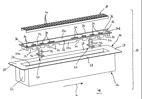
Figures 1 and 2 show a floor drain 10 according to a first embodiment of
the present invention that is used in the construction of walk-in showers.
The floor drain 10 comprises a base body 12, a channel body 14, a frame
16, a cover 18 and two identical spacers 20.
The base body 12 is an elongate and substantially quadrangular styro-
foam block which is provided in its longitudinal direction L with a recess 22
in the form of a groove and open to the top. The recess 22 serves to ac-
commodate a drain pipe and is formed in its upper region such that it
accommodates the channel body 14 substantially with form fit.
The channel body 14 is produced from sheet metal, in particular from
stainless steel or aluminium sheet. Alternatively it can be made of plastic.
It defines a drain channel 24 provided with a drain opening 26 to which a
drain pipe (not shown) can be connected. The drain channel 24 is sur-
rounded by a channel body flange 28 the lower side of which in the fitted
state of the floor drain 10 lies on the upper side of the base body 12.
The frame 16 is also produced from sheet metal, in particular from stainless
steel or aluminium sheet. Alternatively, it can also be made of plastic. It
has side walls 30a, 30b, 30c and 30d arranged like a frame and extending
substantially vertically which define a receiving opening 32. Provided on
the opposing side walls 30a and 30c of the frame 16 are projections 34
protruding into the receiving opening 32 which are in the form of
punched-out and bent sections of the frame 16. On its upper side the
frame 16 is provided with a frame flange 36 which surrounds the receiving
opening 32 like a frame. The frame flange 36 has on its free end a down-
wardly bent frame flange section 38.
CA 02788273 2012-07-26
- 7 -
The cover 18 is a substantially U-shaped profile made of plastic or sheet
metal, in particular noble metal or aluminium sheet, which is provided on
its upper side with a plurality of passage holes 40 to form a grate. Alterna-
tively the cover can also be made without any passage holes 40. In this
case the cover must be somewhat narrower in form and be fixed to the
side so that side drain slots are produced.
According to a further embodiment the cover can also be in the form of
a substantially U-shaped profile that in the intended positioned state is
open to the top so that a floor covering material visible from the outside
can be accommodated in the profile, for example in the form of tiles or
the like.
The spacers 20 respectively have a substantially rectangular plate ele-
ment 42 produced from wood, plastic or metal which is provided with two
threaded bore holes 44 through which an adjusting screw 46 respectively
extends. They serve to adjust the distance between the channel body 14
and the frame 16, as will be described in greater detail in the following.
In order to fit the floor drain 10, in a first step the base body 12 with the
channel body 14 accommodated in the latter and connected to a drain
pipe is positioned on a substrate 48. An incline board (not shown) is then
placed on the base body 12, and this defines an incline in the direction of
the floor drain 10. Alternatively, instead of an incline board screed can
also be used. In a further step the frame 16 is positioned on the channel
body 14 such that its side walls 30a, b, c, d are partially inserted into the
drain channel 24 of the channel body 14. The two spacers 20 are posi-
tioned a distance apart from one another here so that the free ends of
their plate elements 42 engage beneath corresponding projections 34 of
the frame 16, as shown in Figure 2. By turning the adjusting screws 46
which are supported on the bottom of the drain channel 24 of the chan-
nel body 14 the distance between the channel body 14 and the frame 16
can be increased or decreased as one chooses in order to match the
upper side of the frame 16, which is defined by the frame flange 36, to the
height or to the upper side of the floor covering subsequently to be laid.
The floor covering, for example in the form of tiles 50 shown by dashed
CA 02788273 2012-07-26
- 8 -
lines in Figure 2 can now be laid adjacent to the frame flange 36 of the
frame 16. Here the tile adhesive 52 underfills the cavity between the
channel body flange 28 and the frame flange 36, the downwardly bent
frame flange section 38 serving as clamping means.
After the tile adhesive has hardened to such an extent that it can bear
weight, the adjusting screws 46 of the spacers 20 are loosened, where-
upon the spacers 20 can be removed through the receiving opening 32
of the frame 16.
to
In a final step the cover 18 is placed on the projections 34 protruding into
the receiving opening 32 of the frame 16. The upper side of the cover 18
is thus automatically aligned in relation to the upper side of the frame 16
defined by the frame flange 36. The fitting of the floor drain 10 is now
= 15 complete.
The floor drain 10 described above is advantageous in that after adjusting
the distance between the channel body 14 and the frame 16 the spacers
20 can be removed again through the receiving opening 32 of the frame
20 16 so that the spacers 20 can be used a number of times.
Moreover, due
to their design the spacers 20 enable infinite adjustment of the distance,
and so it is not necessary to provide spacers of different heights. Further-
more, two spacers 20 are normally sufficient in order to adjust the distance
of the frame 16 in relation to the channel body 14 while fitting the floor
25 drain 10. Furthermore, the projections 34 of the frame 16
protruding into
the receiving opening 32 and which first and foremost serve as a support
for the cover 18 are used at the same time as an engagement point for
the spacers 20. Accordingly, the frame 16 does not have to be formed
with additional engagement points for the spacers 20.
Figure 3 shows a floor drain 60 according to a second embodiment of the
present invention. The construction of the floor drain 60 corresponds to a
large extent to that of the floor drain 10, and so for the sake of simplicity
the same components are identified by the same reference numbers and
are not described again in the following.
The floor drain 60 only differs from the floor drain 10 with regard to the de-
CA 02788273 2012-07-26
- 9 -
sign of the frame 62 and the spacers 64.
The frame 62 is produced from sheet metal, in particular from stainless
steel or aluminium sheet. Alternatively it can also be made of plastic. It
has substantially vertically extending side walls 30a, 30b, 30c and 30d ar-
ranged like a frame and which define a receiving opening 32. Provided
on the opposing side walls 30a and 30c of the frame 16 are projections 66
protruding into the receiving opening 32 which are in the form of
punched-out and bent sections of the frame 62. The projections 66 corn-
prise at least partially a respective bore hole 68 which is in the form of a
threaded bore hole. On its upper side the frame 62 is provided with a
frame flange 36 which surrounds the receiving opening 32 like a frame.
The frame flange 36 has on its free end a downwardly bent frame flange
section 38.
The spacers 64 of the floor drain 60 according to the second embodiment
of the present invention are adjusting screws which can be screwed into
the threaded bore holes 68 of the projections 66 of the frame 62.
In order to fit the floor drain 60, in a first step the base body 12 is posi-
tioned with the channel body 14 accommodated in the latter and con-
nected to a drain pipe on a substrate 48. An incline board (not shown) is
then placed on the base body 12, and this defines an incline in the direc-
tion of the floor drain 10. Alternatively, instead of an incline board screed
can also be used. In a further step the frame 62 is positioned on the chan-
nel body 14 such that its side walls 300, b, c, d are partially inserted into
the drain channel 24 of the channel body 14. Then the spacers 64 in the
form of adjusting screws are screwed into the bore holes 68 of the projec-
tions 66 of the frame 62 so that they are supported on the bottom of the
drain channel 24 of the channel body 14. By moving the spacers 64 the
distance between the channel body 14 and the frame 62 can now be
increased or decreased as one chooses in order to match the upper side
of the frame 62 which is defined by the frame flange 36 to the height and
to the upper side of the floor covering subsequently to be laid. The floor
covering, for example in the form of tiles (not shown), can now be laid
adjacent to the frame flange 36 of the frame 62. Here - similarly to the
illustration in Figure 2 - the tile adhesive underfills the cavity between the
CA 02788273 2012-07-26
- 10 -
channel body flange 28 and the frame flange 36, the downwardly bent
frame flange section 38 serving as clamping means.
After the tile adhesive has hardened to such an extent that it can bear
weight the spacers 64 in the form of adjusting screws are loosened and
removed through the receiving opening 32 of the frame 62.
In a final step the cover 18 is placed on the projections 66 protruding into
the receiving opening 32 of the frame 62. Here the upper side of the
cover 18 is automatically aligned in relation to the upper side of the frame
62 defined by the frame flange 36. The fitting of the floor drain 60 is now
complete.
The floor drain 60 described above is characterised in particular by the
simple and inexpensive design of the spacers 64. Furthermore, after ad-
justing the distance between the channel body 14 and the frame 62 the
spacers 64 can be removed again through the receiving opening 32 of
the frame 62, and so the spacers 64 can be used a number of times.
Moreover, the spacers 64 in the form of adjusting screws enable infinite
adjustment of the distance, and so it is not necessary to provide spacers
of different heights. Furthermore, four spacers 64 are normally sufficient for
making adjustments to the distance of the frame 62 in relation to the
channel body 14 while fitting the floor drain 60.
Figures 4 to 6 show a floor drain 70 according to a third embodiment of
the present invention and illustrations of components of the latter. The
construction of the floor drain 70 corresponds to a large extent to that of
the floor drain 10, and so the same components are provided with the
same reference numbers and will not be described again in the following.
The floor drain 70 only differs from the floor drain 10 in relation to the de-
sign of its spacers 72.
The spacers 72 of the floor drain 70 according to the third embodiment of
the present invention are designed such that they engage with the frame
flange 36 surrounding the receiving opening 32 of the frame 16. For this
purpose every spacer 72 has two lower elements 74a and 74b engaging
CA 02788273 2012-07-26
- 11 -
beneath the frame flange 36 in the intended positioned state, an upper
element 76 engaging over the frame flange 36 and two adjusting screws
78.
As viewed in the cross-section, each of the identically formed lower ele-
ments 74a and 74b is substantially L-shaped in design and comprises a first
section 80 engaging beneath the frame flange 36 in the intended posi-
tioned state and a second section 82 projecting to the side from the
frame flange 36 in the intended positioned state, a height offset d be-
to tween the first section 80 and the second section 82 corresponding ap-
proximately to the height of the frame flange section 38. The second sec-
tion 82 is provided with a through bore hole 84 which is in the form of a
threaded bore hole.
- 15 The
upper element 76 is in the form of a narrow plate element the length
of which is chosen such that it engages over opposing frame flange sec-
tions. Close to the free ends of the upper element 76 a through bore hole
86 in the form of a threaded bore hole is respectively provided. The lower
elements 74a, b and the upper element 76 are dimensioned such that in
20 the intended
positioned state their through bore holes 84 and 86 are
aligned with one another. In this state the adjusting screws 78 can be
screwed into the through bore holes 84 and 86.
In order to fit the floor drain 70, in a first step the base body 12 with the
25 channel body
14 accommodated in the latter and connected to a drain
pipe is positioned on a substrate 48. An incline board (not shown) is than
placed on the base body 12, and this defines an incline in the direction of
the floor drain 70. Alternatively, instead of an incline board screed can
also be used. In a further step the frame 16 is positioned on the channel
30 body 14 such
that its side walls 30a, b, c, d are partially inserted into the
drain channel 24 of the channel body 14. Spacers 72 are then fitted such
that the two lower elements 74a and 74b engage beneath opposing
frame flange sections, the lower elements 74a and 74b being held in posi-
tion by the upper element 76 engaging over the corresponding frame
35 flange
sections and the two adjusting screws 78. The adjusting screws 78
are supported here on the upper side of the channel body flange 28. By
turning the adjusting screws 78 the space between the channel body 14
CA 02788273 2012-07-26
- 12 -
and the frame 16 can be increased or decreased as one chooses in order
to match the upper side of the frame 16 which is defined by the frame
flange 36 to the height and to the upper side of the floor covering subse-
quently to be laid. The cavity between the channel body flange 28 and
the frame flange 36 can now be underfilled adjacent to the spacers 72
with tile adhesive or fixing mortar.
After the tile adhesive or fixing mortar has hardened to such an extent
that it can bear weight, the adjusting screws 78 can be loosened and the
spacers 72 removed. The floor covering, for example in the form of tiles
(not shown) can then be laid adjacent to the frame flange 36 of the
frame 16. Here the regions of the cavity between the channel body
flange 28 and the frame flange 36 left open previously due to the pres-
ence of the spacers 72 can now be underfilled with tile adhesive or fixing
mortar.
In a final step the cover 18 is placed on the projections 34 protruding into
the receiving opening 32 of the frame 16. Here the upper side of the
cover 18 is automatically aligned in relation to the upper side of the frame
16 defined by the frame flange 36. The fitting of the floor drain 10 is now
complete.
The floor drain 70 described above is advantageous in that after adjusting
the distance between the channel body 14 and the frame 16 and after
the tile adhesive or tile mortar has hardened to such an extent that it can
bear weight the spacers 72 can be removed again, and so the spacers
72 can be used a number of times. Moreover, due to their design the
spacers 72 enable infinite adjustment of the distance, and so it is not nec-
essary to provide spacers 72 with different heights. Further, two spacers 72
are normally sufficient to adjust the distance of the frame 16 in relation to
the channel body while fitting the floor drain 70.
Instead of the spacer disc 72 shown in Figures 4 to 6, substantially U-
shaped spacers 87 as shown in Figure 7 can also alternatively be used.
Each spacer 87 comprises two preferably elastically formed arms 87a and
87h arranged substantially parallel to one another which clamp the frame
flange 36 between them, and a connection arm 87c connecting the
CA 02788273 2012-07-26
- 13 -
arms 87a and 87b to one another. The connection arm 87c is provided
with a through bore hole, preferably in the form of a threaded bore hole,
in order to hold an adjusting screw 78.
Figure 8 shows a channel body 90 of a floor drain according to a further
embodiment of the present invention the construction of which corre-
sponds to that of the floor drain 10 as regards the frame 16, the spacers 20
and the cover 18, and so these components will not be described again.
The channel body 90 resembles to a large extent the channel body 14 of
the floor drain 10 according to the first embodiment, and so the same
components are provided with the same reference numbers and are not
described again. The channel body 90 is produced from sheet metal, in
particular from stainless steel or aluminium sheet. Alternatively, it can also
be made of plastic. It defines a drain channel 24 which is provided with a
drain opening 26 to which a drain pipe (not shown) can be connected.
The drain channel 24 is surrounded by a channel body flange 92 like a
frame. The channel body flange 92 is provided with a series of through
bore holes 94 which are in the form of threaded bore holes.
Moreover, spacers 96 in the form of adjusting screws are provided which
can be screwed into the through bore holes 94 of the channel body
flange 92.
In order to fit the channel body 90, in a first step the spacers 96 in the
form
of adjusting screws are screwed into the through bore holes 94 of the
channel body flange 92. Then the channel body flange 92 is positioned
on a substrate 98 such that the drain opening 96 is aligned with a drain
100 provided in the substrate 98. Here the spacers 96 are supported on
the surface of the substrate 98. By moving the spacers 96 the distance
between the channel body 90 and the substrate 98 can now be in-
creased or decreased as one chooses in order to match the upper side of
the channel body 90 which is formed by the channel body flange 92 to
the height and to the upper side of the screed subsequently to be pro-
duced. When subsequently laying the screed the cavity between the
channel body flange 92 and the substrate 98 is filled with screed. After the
screed has hardened to such an extent that it can bear weight the spac-
CA 02788273 2012-07-26
- 14 -
ers 96 in the form of adjusting screws can then be loosened and removed.
The frame, the floor covering and the cover can then be installed, as de-
scribed above with reference to Figure 2.
Alternatively, the through bore holes 94 formed in the channel body
flange 92 can also be designed without a thread. In this case at least one
nut, which is screwed onto the adjusting screw, is used in order to support
the channel body flange 92.
The previously described channel body 90 is advantageous in that with
the latter the distance between the channel body flange 92 and the sub-
strate 98 can additionally be adjusted infinitely. Furthermore, the spacers
can be removed after fitting the channel body 90 and be used again.
is Moreover, despite its adjustability the channel body 90 has a simple and
correspondingly inexpensive construction.
Alternatively, in order to adjust the height between the channel body 90
and the substrate 98, instead of the spacers 96, spacers can also be used
which are designed similarly to the spacers 72 shown in Figures 4 to 6, only
that the latter engage with the channel body flange 92, and not with the
frame flange section 38.
CA 02788273 2012-07-26
,
- 15 -
List of reference numbers
floor drain 70 floor drain
12 base body 72 spacer
14 channel body 74a,b lower element
16 frame 76 upper element
18 cover 78 adjusting
screw
spacer 80 first section
22 recess 82 second section
24 drain channel 84 through bore
hole
26 drain opening 86 through bore
hole
28 channel body flange 87 spacer disc
a, b, c, d side wall 87a,b arm
' 32 receiving opening 87c connection arm
34 projection 88 through bore
hole
36 frame flange 90 channel body
38 frame flange section 92 channel body
flange
passage hole 94 through bore hole
42 plate element 96 spacer
44 threaded bore hole 98 substrate
46 adjusting screw 100 drain
48 substrate
tile
52 tile adhesive
floor drain
62 frame
64 spacer
66 projection
68 bore hole