Note: Descriptions are shown in the official language in which they were submitted.
= CA 2788555 2017-02-23
PORTABLE PRINTER WITH ASYMMETRICALLY-DAMPED MEDIA CENTERING
BACKGROUND
[0002] The present disclosure relates to continuous feed printers,
and more particularly, to a
portable label or thermal printer having a selectively adjustable,
asymmetrically damped media
centering assembly.
[0003] Portable or desktop printers are often used in commercial
settings, e.g., in
warehouses, in industrial and manufacturing environments, by shipping
services, in vending
machine routes, in the vending and gaming industries, and in retail
establishments for ticket
printing and inventory control. Ideally, portable printers weigh only a few
pounds and are small
enough to be easily carried during use and/or easily attached to a buckle or a
harness-typc
device. This enables the user to print labels or receipts on demand without
having to retrieve a
printed label from a printing station. Because the printer is portable, the
printer may include a
power source, such as a disposable or rechargeable battery, and may
additionally communicate
with a host terminal or network connection via a wireless interface, such as a
radio or optical
interface. A portable printer may utilize sheet-fed media, or, more popularly,
continuous-feed
media, e.g., rolls of paper, labels, tags, and thc like. Portable printers
commonly employ direct
CA 02788555 2012-07-30
WO 2011/102859 PCT/US2010/052653
thermal transfer techniques, whereby thermochromic media passes over a thermal
print head
which selectively heats areas of the media to create a visible image. Also
popular are thermal
transfer printers which employ a heat-sensitive ribbon to transfer images to
media.
[0004] A continuous feed printer is particularly suitable for printing onto
stock material
which may include, but is not necessarily limited to, labels, receipts, item
labels, shelf
labels/tags, ticket stubs, stickers, hang tags, price stickers, and the like.
Label printers may
incorporate a media supply of "peel away" labels adhered to a coated substrate
wound in a rolled
configuration. Alternatively, a media supply may include a plain paper roll
suitable for ink-
based or toner-based printing. Continuous media is typically supplied in
rolls, and is available in
a wide range of widths. The roll media may be wound around a generally tubular
core which
supports the roll media. The core may have a standard size, or arbitrarily-
sized inner diameter.
In use, the media is drawn against a printing head, which, in turn, causes
images to be created on
the media stock by, e.g., impact printing (dot matrix, belt printing), by
localized heating (thermal
transfer printing), inkjet printing, toner-based printing, or other suitable
printing methods.
[0005] Portable or thermal printers may be designed for use with one type
of printing media
or one particular size of print media, e.g., 2-inch label stock or 3-inch
label stock. Other portable
printers may be configurable to accommodate different media types and sizes.
Such printers
may include a media centering mechanism which is designed to accommodate roll
media of
varying widths and/or core diameters. The media centering mechanism may
include opposing
support members configured to engage the media roll core. A media centering
mechanism
typically includes first and second support members that are generally biased
towards each other
to sccure the media roll. Movement of the first and second support members may
be
2
CA 02788555 2012-07-30
WO 2011/102859 PCT/US2010/052653
synchronized by one or more gears or belts such that, when a support member is
moved a
distance from the centerline of the media roll, the other support member moves
a corresponding
distance in the opposing direction from the centerline of the media roll.
[0006] Many of the media centering mechanisms associated with portable
printers are not
particularly versatile or convenient to use, and may employ various spring-
loaded elements that
are intended to accommodate media of various types and sizes. As a result,
even though certain
portable printers may accommodate media of various sizes, to load such media a
user must
manipulate the spring-loaded members and other mechanical elements using both
hands. Such
spring-loaded elements can suddenly snap into position with considerable
force, which may
result in an unpleasant user experience, damage to the print media, and even
damage to the
printer itself.
SUMMARY
[0007] The present disclosure is directed to a portable printer having an
asymmetrically-
damped media centering mechanism. The mechanism allows a user to open the
spring-loaded
media support members with ease, but, upon release, damping is provided to the
media support
members to cause the retraction thereof to occur at slower, controlled rate.
In this manner, the
disclosed media centering mechanism may facilitate easier media loading
(including one-handed
loading), may provide an improved user experience, and may prevent damage to
the print media
and/or to the printer.
[0008] The dampening mechanism includes a damping gear, and a pivoting arm
having at
least one idler gear wherein the pivoting arm pivots between at least a first,
non-damped position
and a second, damped position in response to movement of a media support
member. The
3
CA 02788555 2012-07-30
WO 2011/102859 PCT/US2010/052653
damping gear includes a rotational resistance element, such as, without
limitation, damping
grease, a frictional mechanism, a regenerative braking mechanism, a magnetic
braking
mechanism, a centrifugal governor, and combinations thereof and/or of other
suitable rotational
resistance elements now or in the future known. The idler gear cooperates with
one or more
drive elements associated with the media support member, such as without
limitation, a rack and
pinion drive and/or a belt drive. The pivot arm is arranged such that, when a
media support
member is moved toward an open position, the drive element causes the pivot
arm to move into
the non-damped position wherein the idler gear on the pivot arm is disengaged
from the damping
gear, thus allowing free movement of the media support member. When the media
support
member moves toward the closed position, the pivot arm moves into the damped
position
wherein the idler gear on the pivot arm engages the damping gear, which in
turn slows the
motion of the drive element and media support member. In this manner,
asymmetrical damping
is achieved whereby the media support members open freely against only the
spring force, but
retract slowly with the dampening effect as the idler gear engages the
dampening gear.
[0009] An asymmetrically-damped media centering mechanism is disclosed
which includes a
first media support member moveable along a longitudinal axis thereof and a
second media
support member moveable along a longitudinal axis thereof. The first and
second media support
members may share a common longitudinal axis of movement. The disclosed media
centering
mechanism includes a reciprocal movement mechanism operably coupled to the
first and second
media support members that is configured to translate a longitudinal movement
of the first media
support member into a corresponding opposite longitudinal movement of the
second media
support member. The media centering mechanism further includes a pivoting arm
coupled to the
reciprocal movement mechanism. The pivoting arm is pivotable between at least
a first and a
4
CA 02788555 2012-07-30
WO 2011/102859 PCT/US2010/052653
second position. During use, the pivoting arm pivots to the first position
when the first and
second media support members are moved closer to each other (e.g., when
grasping or closing
onto a media roll positioned therebetween), and the pivoting arm pivots to the
second position
when the first and second media support members are moved further apart from
each other (e.g.,
when spreading the media support members to insert a media roll therebetween).
A damping
gear is provided that is configured to engage the reciprocal movement
mechanism when the
pivoting arm is in the first position. The reciprocal movement mechanism may
include a first
and second drive member operably coupled to the first and second media support
members,
respectively, and may include a drive belt operably coupled to the first and
second drive
members and at least partially disposed around the driven gear. Additionally
or alternatively, the
reciprocal movement mechanism may include a first and second rack member
operably coupled
to the first and second media support members, respectively, wherein a pinion
gear is operably
engageable with the first and second rack members and configured to translate
movement of the
first rack member into a corresponding opposite movement of the second rack
member. In
embodiments, the pinion gear is axially coupled to the driven gear.
[0010] Also disclosed is a method of centering a media roll, comprising the
steps of
providing a first and a second media support member moveable along a
longitudinal axis and
dimensioned to axially engage a media roll. The method includes the step of
providing a
reciprocal movement mechanism operably coupled to the first and second media
support
members wherein a longitudinal movement of one media support member causes a
corresponding opposite longitudinal movement of the other media support
member. A pivoting
arm is provided, which operably couples to the reciprocal movement mechanism,
wherein the
pivoting arm pivots to the first position when the media support members are
moved closer to
CA 02788555 2012-07-30
WO 2011/102859 PCT/US2010/052653
each other, and the pivoting arm pivots to the second position when the media
support members
are moved further apart from each other. A damping gear is provided which is
configured to
engage the reciprocal movement mechanism when the pivoting arm is in the first
position.
[0011] Also disclosed is a portable printer that includes a display having
an overmolded
bezel associated therewith. The overmolded bezel is formed from resilient
material that provides
shock resistance and which protects the display, printer, and associated
components thereof from
damage in the event the portable printer is dropped or otherwise mishandled.
In embodiments,
the overmolded bezel is formed from VersollanTm OM 1255NX-9, a thermoplastic
elastomer
manufactured by PolyOne Corporation of Avon Lake, Ohio, USA. The overmolded
bezel
additionally or alternatively seals the display and printer to resist the
infiltration of contaminants,
e.g., dust and moisture, into the display and/or printer.
[0012] Disclosed is a portable printer having ergonomic enhancements. In
embodiments, a
printer in accordance with the present disclosure includes a media loading
arrangement capable
of single-handed operation. A media cover may be unlatched using a lever
operable by a single
hand. Using a single hand, the media cover may be fully unlatched, e.g., both
sides freed from
an associated housing, such that the media cover swings clear of the housing
to expose a media
storage well. Media may be loaded into the media storage well and the media
cover closed with
one hand. Single-handed operation may provide a number of benefits. In one
envisioned
scenario, the portable printer may be hung from the waistbelt of a user, e.g.,
a warehouse worker.
Such a worker is often situated precariously, such as on a forklift, on an
elevated platform of a
Hi-Lo machine, and the like, wherein using two hands to inanipulate a portable
device may be
6
CA 02788555 2012-07-30
WO 2011/102859 PCT/US2010/052653
hazardous. By facilitating one-handed operation, a portable printer in
accordance with the
present disclosure may offer safer, more convenient, and more reliable
operation.
[0013] In another aspect, a portable printer in accordance with the present
disclosure
includes a dual wall, frame housing that provides improved strength and shock
resistance. The
dual wall construction includes a continuous inner frame structure adapted to
support one or
more internal printer components, which may include, without limitation, a
printhead, a roller
assembly, a drive assembly, media centering assembly, and/or a battery
assembly. The inner
frame is surrounded at least in part by a second, outer structure that
provides additional stiffness,
strength, and drop resistance. The housing includes a media access opening and
a corresponding
media access cover configured to facilitate the loading of media into the
printer. The size of the
media access opening is kept to the minimum size necessary to accommodate the
media for use
with the printer. By minimizing the media opening, greater space is available
for the inner frame
and/or the outer structure, further improving the strength, rigidity, and
impact resistance of the
printer.
[0014] The disclosed printer may include one or more connectors that extend
from the
interior of housing to the exterior. While the connector(s) may include an
electrical connector,
other connector types are contemplated within the scope of the present
disclosure, e.g., moisture-
proof connectors, fluidic connectors, security connectors (e.g., K-Slot), and
the like. In
embodiments, two electrical connectors are provided, wherein a first connector
is adapted to
couple a source of electrical power to the printer and a second connector is
adapted to couple a
data signal to the printer. In embodiments, the disclosed printer may include
a USB connector, a
serial (e.g., RS-232, RS-422, RS-485), connector, a Firewire (IEEE-1394)
connector, a network
7
CA 02788555 2012-07-30
WO 2011/102859 PCT/US2010/052653
(10Base-T, 100Base-TX, and 1000Base-T) connector, and/or a parallel (IEEE
1284) connector.
The disclosed printer may additionally or alternatively include a dust cover
assembly that is
adapted to cover one or more connectors. The dust cover assembly includes a
cap portion that is
dimensioned to seal the one or more connectors associated with the dust cover.
In embodiments,
the dust cover is formed from resilient material. The cover is joined to a
base by a resilient hinge
or tethering member that retains the cap portion to the base. The cap, hinge
member, and base
may be integrally formed. The hinge member may be a living hinge. The base is
retained to the
printer by any suitable manner of fastening, including without limitation,
threaded fasteners,
clips, tabs, and the like. Advantageously, the dust cover assembly may be user-
replaceable, so
that a worn or broken dust cover assembly may be readily replaced with a new
dust cover
assembly. In embodiments, a spare dust cover assembly may be stored within a
recess provided
by the printer housing.
[0015] A portable printer having a media feed cover assembly is disclosed.
In certain
applications, it may be desirable to feed media into the printer from an
external media source.
To facilitate external media feeding, the disclosed printer includes a media
feed opening defined
in the housing. A media feed cover is provided to seal the media feed opening
from moisture,
dust, and other contaminants. The media feed cover is supported by a pocket
formed between
the outer enclosure and the inner frame. The cover assembly is configured to
provide two or
more detents to enable the cover to be positioned in an open and a closed
position. In an
embodiment, the pocket includes a recess in the open and closed position that
provides detents
for each of the open and closed positions.
8
CA 02788555 2012-07-30
WO 2011/102859 PCT/US2010/052653
[0016] Also disclosed is a portable printer that includes an upper inner
frame structurally
associated with a lower inner frame to form an inner support structure. An
asymmetrically-
damped media centering assembly is fixed to the inner support structure. An
upper housing and
a lower housing are joined to the inner support structure to form a dual-wall
housing assembly.
A media opening defined in the upper housing exposing a media well, and a
media access door
having at least a closed position and an open position is operatively
associated with the media
opening. A latch assembly having a first, normally latched position and a
second, unlatched
position, the latch assembly is associated with the inner support structure
and is configured to
retain the media access door in the closed position when the latch is in the
latched position, and
to release the media access door when the latch is in the unlatched position.
BRIEF DESCRIPTION OF THE DRAWINGS
[0017] Various embodiments of the subject instrument are described herein
with
reference to the drawings wherein:
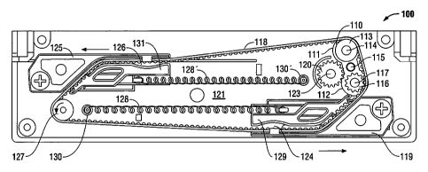
[0018] Fig. 1 is a view of an embodiment of an asymmetrical damping
mechanism in
accordance with the present disclosure shown in a first, non-damped position;
[0019] Fig. 2 is a view of the Fig. 1 embodiment of an asymmetrical damping
mechanism in
accordance with the present disclosure shown in a second, damped position;
[0020] Fig. 3 is a cross-sectional view of a pivot arm of the Fig. 1
embodiment of an
asymmetrical damping mechanism in accordance with the present disclosure;
[0021] Fig. 4 is a cross-sectional view of a damping gear of the Fig. 1
embodiment of an
asymmetrical damping mechanism in accordance with the present disclosure;
9
CA 02788555 2012-07-30
WO 2011/102859 PCT/US2010/052653
[0022] Fig. 5 is a perspective view of another embodiment of an
asymmetrical damping
mechanism in accordance with the present disclosure shown in a first, non-
damped position;
[0023] Fig. 6 is a perspective view of the Fig. 5 embodiment of an
asymmetrical damping
mechanism in accordance with the present disclosure shown in a second, damped
position;
[0024] Fig. 7 is a perspective view of yet another embodiment of an
asymmetrical damping
mechanism in accordance with the present disclosure shown in a first, non-
damped position;
[0025] Fig. 8 is a perspective view of the Fig. 7 embodiment of an
asymmetrical damping
mechanism in accordance with the present disclosure shown in a second, damped
position;
[0026] Fig. 9 is a view of still another embodiment of an asymmetrical
damping mechanism
in accordance with the present disclosure shown in a first, non-damped
position;
[0027] Fig. 10 is a view of the Fig. 9 embodiment of an asymmetrical
damping mechanism
in accordance with the present disclosure shown in a second, damped position;
[0028] Fig. 11 is a perspective view of an embodiment of a portable printer
in accordance
with the present disclosure;
[0029] Fig. 12 is another perspective view of the Fig. 11 embodiment of a
portable printer in
accordance with the present disclosure;
[0030] Fig. 13 is an exploded view of the Fig. 11 embodiment of a portable
printer in
accordance with the present disclosure;
[0031] Fig. 14 illustrates an inner frame of an embodiment of a portable
printer in
accordance with the present disclosure; and
CA 02788555 2012-07-30
WO 2011/102859 PCT/US2010/052653
[0032] Fig 15 illustrates an embodiment of a dust cover assembly for a
portable printer in
accordance with the present disclosure.
DETAILED DESCRIPTION
[0033] Particular embodiments of the present disclosure are described
hereinbelow with
reference to the accompanying drawings; however, it is to be understood that
the disclosed
embodiments are merely exemplary of the disclosure, which may be embodied in
various forms.
Well-known and/or repetitive functions and constructions are not described in
detail to avoid
obscuring the present disclosure in unnecessary or redundant detail.
Therefore, specific
structural and functional details disclosed herein are not to be interpreted
as limiting, but merely
as a basis for the claims and as a representative basis for teaching one
skilled in the art to
variously employ the present disclosure in virtually any appropriately
detailed structure. In
addition, as used herein, terms referencing orientation, e.g., "top",
"bottom", "up", "down",
"left", "right", "clockwise", "counterclockwise", and the like, are used for
illustrative purposes
with reference to the figures and features shown therein. It is to be
understood that embodiments
in accordance with the present disclosure may be practiced in any orientation
without limitation.
In this description, as well as in the drawings, like-referenced numbers
represent elements which
may perform the same, similar, or equivalent functions.
[0034] With reference to Figs. 1-4, an embodiment of an asymmetrically-
damped media
centering mechanism 100 is shown. The disclosed mechanism 100 is adapted for
use with a
toothed drive belt 118 that is operably coupled to a first media support drive
member 119 and a
second media support drive member 125. While a toothed drive belt is shown,
any suitable belt
or chain may be used (e.g., vee belt, round belt, flat belt, drive chain,
etc.). As shown, first drive
1 I
CA 02788555 2012-07-30
WO 2011/102859 PCT/US2010/052653
member 119 engages drive belt 118 within a notched region 124. Second drive
member 125
engages belt 118 within notched region 126. It should be noted that any
suitable manner of
attachment may be utilized such that linear motion of drive members 119, 125
is translated
to/from drive belt 118. The disclosed arrangement of drive belt 118, first
drive member 119, and
second drive member 125 provides for reciprocal linear movement of drive
member 119 with
respect to movement of drive member 125. First drive member 119 and second
drive member
125 may be slidably associated with one or more guides (not explicitly shown)
that are
configured to constrain the movement thereof to a substantially longitudinal
axis of motion
corresponding to the movement of belt 118.
[0035] A pivot arm 110 that is rotatable around a pivot pin 115 is disposed
on a support
member 121. Pivot arm 110 includes a first idler gear 113 and a driven gear
116 rotatably
mounted thereupon adjacent to opposite ends 111 and 112, respectively, of
pivot arm 110. First
idler gear 113 and driven gear 116 are positioned on pivot arm 110 in
essentially coplanar
alignment with drive belt 118. Drive belt 118 is disposed around idler gears
113 and 116 at one
end of the mechanism 100, and around a second idler gear 127 at an opposite
end of mechanism
100. As shown, drive belt 118 is continuous, however, drive belt 118 may be
discontinuous or
segmented.
[0036] A biasing member 128 is disposed between a free end 129 of drive
member 119 and
an anchor 130 and adapted to bias drive member 119 away from pivot arm 110.
Additionally or
alternatively, a biasing member 128' may be disposed between a free end 131 of
drive member
125 and a corresponding anchor 130'. Biasing member 128 and/or biasing member
128' may
include an extension spring. At rest, biasing member 128 causes drive member
119 to be drawn
12
CA 02788555 2012-07-30
WO 2011/102859 PCT/US2010/052653
leftward, and drive member 125 to be drawn rightward, e.g., causes both drive
members 119,
125 to be drawn generally towards the center of centering mechanism 100. A
media support
member (not explicitly shown) is associated with each of drive member 119, 125
to retain a
media roll therebetween, as described herein.
10037) The disclosed media centering mechanism includes a damping gear 120
that is
configured to engage driven gear 116. With particular reference to Fig. 4,
damping gear 120 is
associated with damping grease 122 that is applied between a movable surface
132 of damping
gear 120 and a stationary surface, e.g., support member 121 and/or pin 123. It
is envisioned that
any suitable damping grease, such as without limitation, SmartGreaseTM
Fluorocarbon Gel,
manufactured by Nye Lubricants, Inc. of Fairhaven, Massachusetts, United
States, may be
utilized. Damping grease 122 resists the rotational motion of damping gear
120.
[0038] Referring again to Fig. 1, during use, first drive member 119 and/or
second drive
member 125 may be caused to be moved in a direction indicated by the arrows,
e.g., generally
outwardly from the center of mechanism 100, overcoming the biasing force of
biasing member
128, and causing belt 118 to traverse in a generally counterclockwise
direction. The
counterclockwise motion of belt 118 is translated through first idler gear 113
and/or driven gear
116 to cause a corresponding counterclockwise rotation of pivot arm 110,
which, in turn, causes
driven gear 116 to disengage from damping gear 120. In this manner, the
outward linear motion
of first drive member 119 and second drive member 125 is unimpeded by damping
gear 120 thus
enabling a user to freely open the media support members (not explicitly
shown) associated
therewith to facilitate the introduction of a media roll therebetween.
13
CA 02788555 2012-07-30
WO 2011/102859 PCT/US2010/052653
[0039] Continuing now with reference to Fig. 2, the first drive member 119
and/or second
drive member 125 may be caused to be moved in the opposite direction
(generally inwardly
towards the center of mechanism 100) by, e.g., the biasing force of biasing
member 128. The
described inward motion of first drive member 119 and second drive member 125,
in turn,
causes belt 118 to traverse in a generally clockwise direction. The clockwise
motion of belt 118
is translated through first idler gear 113 and/or driven gear 116 to cause a
corresponding
clockwise rotation of pivot arm 110, which, in turn, engages driven gear 116
with damping gear
120. The rotational resistance of damping gear 120 is translated through
driven gear 116 to belt
118, which slows the movement of first drive member 119 and second drive
member 125, and
the media support members associated therewith. Thus, the dampening effect of
engaged
dampening gear 120 enables the return, or closing, of the first drive member
119 and second
drive member 125, and the media support members associated therewith, to be
achieved in a
smooth and controlled manner.
[0040] Other embodiments are contemplated wherein a second damping gear
(not explicitly
shown) may be employed to provide damping in a direction opposite to that
provided by a first
damping gear. In one arrangement, the second damping gear is arranged such
that the pivot arm
causes the second damping gear to engage one or more of the idler or driven
gears mounted
thereupon when the drive member(s) move in an opening direction.
[0041] Turning now to Figs. 5 and 6, an embodiment of a print media
subassembly 200
having an asymmetrically damped media centering mechanism 201 is shown. Print
media
subassembly includes a housing 205 having defined therein a media storage well
250 that is
dimensioned to accommodate a variety of roll-fed media. Housing 205 includes a
support
14
CA 02788555 2012-07-30
WO 2011/102859
PCT/US2010/052653
member 221 configured to support media centering mechanism 201 as described
herein.
Housing 205 includes one or more mounting bosses 251 configured to accept a
fastener, pin, or
other structural or connective element. The disclosed mechanism 201 includes a
drive belt 218
that is operably coupled to a first media support drive member 219 and a
second media support
drive member 225. While a toothed drive belt 218 is shown, any suitable belt
or chain may be
used as described herein. As shown, first drive member 219 engages drive belt
218 within a
notched region 224. Second drive member 225 engages belt 218 within notched
region 226.
First and second drive members 219, 225 include a retention tab 249 that is
configured to retain
belt 218 within notched region 224 and notched region 226, respectively. It
should be noted that
any suitable manner of retention may be utilized such that linear motion of
drive members 219,
225 is translated to/from drive belt 218.
[0042]
Drive belt 218, first drive member 219, and second drive member 225 provide
for
reciprocal linear movement of drive member 219 with respect to movement of
drive member
225. First drive member 219 is slidably disposed within a slot 242 that is
defined in support
member 221 and includes a wide portion 244 and a narrow portion 243. Second
drive member
225 is slidably disposed within a slot 245 that is defined in support member
221 and includes a
wide portion 247 and a narrow portion 246. Slots 242 and 245 are configured to
constrain the
movement of drive members 219, 225, respectively, to a substantially
longitudinal axis of motion
corresponding generally to the movement of belt 218. A positive stop 248 is
disposed at an end
of slot narrow portion 243 and/or slot narrow portion 246 and configured to
limit the longitudinal
travel of drive member 219 and/or drive member 225, respectively.
CA 02788555 2012-07-30
WO 2011/102859 PCT/US2010/052653
[0043] A pivot arm 210 that is rotatable around a pivot pin 215 is disposed
on a support
member 221. Pivot arm 210 includes a first idler roller 213 and a driven gear
216 rotatably
mounted on pivot arm 210. First idler roller 213 and driven gear 216 are
positioned on pivot arm
210 in essentially coplanar alignment with drive belt 218. Drive belt 218 is
disposed around first
idler roller 213 and driven gear 216 at one end of the mechanism 201, and
around a second idler
roller 227 at an opposite end of mechanism 201. As shown, drive belt 218 is
continuous,
however, drive belt 218 may be discontinuous or segmented.
[0044] An extension spring 228 is disposed between an anchor pin 230
provided on support
member 221, and a mounting tab 229 provided on drive member 219. As can be
readily
appreciated, extension spring 228 is configured to bias drive member 219 away
from pivot arm
210, which, by operation of drive belt 218, first idler roller 213, driven
gear 216, and second
idler roller 227, serves to bias drive member 225 toward pivot arm 210 in a
reciprocally
synchronized manner. Biasing member 228 causes drive member 219 to be drawn
leftward, and
drive member 225 to be drawn rightward, e.g., causes both drive members 219,
225 and media
support members 240, 241 respectively associated therewith to be drawn
generally towards the
center of storage well 250 to retain a roll of media therebetween.
[0045] First media support member 240 is operatively associated with drive
member 219,
and second media support member 241 is operatively associated with drive
member 225. As
shown, media support members 240, 241 are joined to drive members 219, 225,
respectively, by
a fastener 252 which may include a threaded fastener, rivet, pin, or clip,
however, any suitable
manner or combination of attachment may be utilized, including without
limitation, chemical
16
CA 02788555 2012-07-30
WO 2011/102859 PCT/US2010/052653
bonding, adhesive, welding, and the like. Media support member 240, 241 may be
integrally
formed with drive member 219, 225, respectively.
[0046] The disclosed media centering mechanism includes a damping gear 220
that is
configured to engage with driven gear 216. Damping gear 220 is associated with
damping
grease (not explicitly shown) that is applied between a movable surface of
damping gear 220 and
a stationary surface, e.g., support member 221 and/or pin 223 and adapted to
resist the rotational
motion of damping gear 220. Any suitable damping grease (as previously
described herein) may
be utilized.
[0047] During use, a user loads a roll of media by opening one or both
media support
members 240, 241, inserting a roll of media (not explicitly shown) and
releasing the media
support members 240, 241 which retain the media roll under tension provided by
extension
spring 228. In greater detail, a user moves first media support member 240
and/or second media
support member 241 generally outwardly from the center of mechanism 201,
thereby
overcoming the biasing force of extension spring 228, and causing belt 218 to
traverse in a
generally counterclockwise direction. The counterclockwise motion of belt 218
is translated
through idler roller 213 and/or driven gear 216 to cause a corresponding
counterclockwise
rotation of pivot arm 210, which, in turn, causes driven gear 216 to disengage
from damping gear
220. In this manner, the outward linear motion of first drive member 2 19 and
second drive
member 225 is unimpeded by damping gear 220 thus enabling a user to freely
open media
support members 240, 241 associated therewith to facilitate the introduction
of a media roll
therebetween.
17
CA 02788555 2012-07-30
WO 2011/102859 PCT/US2010/052653
[0048] Continuing, a user may relax pressure on, or release completely,
media support
members 240, 241 to allow first drive member 219 and/or second drive member
225 to move in
the opposite direction, e.g., closing direction generally inwardly towards the
center of
mechanism 201 by e.g., the biasing force of extension spring 228. The
described inward motion
of first drive member 219 and second drive member 225, in turn, causes belt
218 to traverse in a
generally clockwise direction. The clockwise motion of belt 218 is translated
through first idler
roller 213 and/or driven gear 216 to cause a corresponding clockwise rotation
of pivot arm 210,
which, in turn, engages driven gear 216 with damping gear 220. The rotational
resistance of
damping gear 220 is translated through driven gear 216 to belt 218, which
slows the movement
of first drive member 219, second drive member 225, and the associated media
support members
240, 241. Thus, the dampening effect of engaged dampening gear 220 enables the
return, or
closing, of media support members 240, 241 to be achieved in a smooth and
controlled manner.
[0049] With reference now to Figs. 7 and 8, an embodiment of an
asymmetrically-damped
media centering mechanism 300 employing a rack and pinion arrangement is
shown. The
disclosed media centering mechanism 300 includes a first media support member
340 and a
second media support member 341. The first and second media support members
340, 341 are
joined respectively to rack members 342, 343 that extend inwardly towards the
center of
mechanism 300. The media support members 340, 341 may be joined to the
respective rack
member 342, 343 by any suitable manner of attachment, including threaded
fasteners, adhesive,
welding, clips. Additionally or alternatively, media support members 340, 341
may be integrally
formed with the respective rack member 342, 343 thereof.
18
CA 02788555 2012-07-30
WO 2011/102859 PCT/US2010/052653
[0050] Rack members 342, 343 are reciprocally synchronized by pinion gear
314 that is
axially coupled to driven gear 313, such that pinion gear 314 and driven gear
313 rotate in
tandem. Pinion gear 314 and driven gear 313 may be positively joined by a
common shaft (not
explicitly shown) and/or may be integrally formed. Media support members 340,
341 are biased
toward each other by an extension spring 328 that is fixed to media support
members 340, 341
by a retention clip 330. The biasing force of extension spring 328 is
sufficient to secure a media
roll (not explicitly shown) between media support members 340, 341. Media
support members
340, 341 may include media hubs 344, 345, respectively, that are dimensioned
to operatively
engage an inner diameter (e.g., a core) of a media roll.
[0051] A damping gear 320 rotatably mounted on pin 323 is associated with
damping grease
322 that is applied between a movable surface of damping gear 320 and an
adjacent stationary
surface (not explicitly shown) and/or pin 323. Damping gear 320 is adapted to
resist the
rotational motion thereof by the viscous friction provided by damping grease
322. As described
elsewhere herein, any suitable damping grease may be utilized. In embodiments,
additional or
alternative friction-inducing elements may be employed in association with
damping gear 320,
including without limitation magnetic elements, inertial elements (e.g., a
flywheel), clockworks
elements, clutch mechanisms, and the like.
[0052] Pinion gear 313 engages movable gear 316 that is rotatably mounted
on a pivot arm
310 that is configured to pivot on an axis (not explicitly shown) such that,
when media support
members 340, 341 are moved apart from each other (e.g., when loading a media
roll), pivot arm
310 swings movable gear 316 away from damping gear 320, thereby disengaging
movable gear
316 and damping gear 320. Conversely, when media support members 340, 341 are
moved
19
CA 02788555 2012-07-30
WO 2011/102859 PCT/US2010/052653
toward from each other (e.g., when a media roll is grasped therebetween for
use), pivot arm 310
swings movable gear 316 towards damping gear 320, thereby engaging movable
gear 316 and
damping gear 320. In an embodiment, the pivot axis of pivot arm 310 is
coincident with the
rotational axis of driven gear 313 and/or pinion gear 314. The pivoting motion
of pivot arm 310
may be induced by parasitic friction that may be present among and between
driven gear 313,
pinion gear 314, and/or pivot arm 310, and associated components thereof.
Thus, the dampening
effect of engaged dampening gear 320 enables the return, or closing, of media
support members
340, 341 to be achieved in a smooth and controlled manner while permitting the
opening of
media support members 340, 341 to be performed without any appreciable
resistance apart from
that provided by extension spring 328.
[0053] Turning to Figs. 9 and 10, still another embodiment of an
asymmetrical damping
mechanism 400 in accordance with the present disclosure is shown wherein a
damping roller 420
is disposed outside of a perimeter defined by drive belt 418. Drive belt 418
is of a toothed type
having a plurality of drive teeth 421 disposed on at least an outer surface
419 thereof. A pivoting
arm assembly 410 is configured such that as the drive belt moves in a
clockwise direction, e.g., a
direction corresponding to the closing of a pair of media support members (not
explicitly
shown), the pivoting arm 410 rotates in a clockwise direction, causing the
outer teeth 421 of
drive belt 418 to engage damping roller 420.
[0054] Turning to Figs. 11 and 12, an embodiment of a portable printer 500
in accordance
with the present disclosure includes a control panel 523 having an overmolded
bezel 520
associated therewith. The overmolded bezel 520 is formed from resilient
material that may
provide shock resistance and prevent the infiltration of contaminants into the
control panel 523,
CA 02788555 2012-07-30
WO 2011/102859 PCT/US2010/052653
printer 500, user interface element(s) 524, and components associated
therewith. The control
panel 523 includes a display 522 that is adapted to present operational
information to a user. By
way of example, and without limitation, the display 522 may present status
information,
diagnostic information, setup information, and the like. Display 522 may
include a text display,
a graphical display, a monochrome display, a color display, and may include
any display means
now or in the future known, including without limitation a liquid crystal
display (LCD), a light
emitting diode (LED) display, an organic light emitting diode (OLED) display,
a vacuum
fluorescent display, and the like. Control panel 523 includes one or more user
interface elements
524, e.g., buttons and/or switches, adapted to accept user inputs. The
overmolded bezel 520 may
include the one or more user interface elements 524, such that the resilient
material of the bezel
520 provides a seal associated with the one or more user interface elements
524.
[00551 Printer 500 includes a housing 540 having an upper housing 542 and a
lower housing
544. A media access door 510 is provided to facilitate the loading and
unloading of media (not
explicitly shown) in a media well 550. As shown in Fig. 13, media centering
assembly 560 is
positioned within media well 500. Media centering assembly includes a pair of
media support
members 561 and an asymmetrically-damped centering mechanism 562 as described
hereinabove. Printer 500 includes a belt clip 526 affixed to the lower housing
544 thereof. Belt
clip 526 may be removably coupled to lower housing 544 by any suitable manner
of attachment,
such as without limitation threaded fasteners, one or more clips, and the
like.
[00561 Printer 500 includes an upper inner frame 548, as shown in Fig. 14,
and a lower inner
frame 546. The combination of upper inner frame 548 and lower inner frame 546
provides an
inner support structure, which, in combination with upper housing 542 and
lower housing 544,
21
CA 02788555 2012-07-30
WO 2011/102859 PCT/US2010/052653
forms a dual-wall housing assembly that provides increased impact resistance
and rigidity. Latch
lever 530 is operably associated with media cover 510 such that actuation of
latch lever 530
disengages one or more latches (not explicitly shown) to permit media cover
510 to open. Media
cover 510 is configured to be positioned in at least a first, closed position
as shown in Fig. 11
and a second, open position as shown in Fig. 12. Detents are provided in
association with media
cover 510 to retain media cover 510 in each of the open and closed positions.
A spring (not
explicitly shown) may be associated with media cover 510 and configured to
bias media cover
510 toward an open position as shown in Fig. 12. Upper inner frame 548
provides support for
latch lever 530. An opening 532 is defined in housing 540 to facilitate access
to and actuation of
latch lever 530. A fingertip recess 531 is defined in latch lever 530 to
enable the convenient
actuation thereof by, e.g., the fingertip of a user. In this manner, media
cover 510 may be
unlatched using a single-handed motion to expose media storage well 550 for
loading and
loading media. A media roller 536 is operably associated with upper inner
frame 548 to
facilitate feeding of media along a print path.
[0057] Lower inner frame 546 includes a battery well 561 that is adapted to
operably receive
a battery pack 560. Battery pack 560 may include one or more cells, which may
be connected in
series, in parallel, or in a combination of series and parallel, to provide
operating power to printer
500. Battery pack 560 may include a primary battery (e.g., non-rechargeable),
a secondary
battery (e.g., rechargeable), and or combinations thereof. Battery pack 560
may include an
identifier, e.g., a physical, an electrical, or an optical identifier, that
identifies to the printer 500
one or more characteristics of the battery pack 560. Such characteristics may
include, without
limitation, a voltage, an amperage, an ampere-hour rating, a battery type
(e.g., NiCd, NiMH, Li-
ion), and a charge cycle count.
22
CA 02788555 2012-07-30
WO 2011/102859 PCT/US2010/052653
[0058] As shown in Fig. 15, printer 500 includes dust cover assembly 570
that is
dimensioned to cover one or more connectors (not explicitly shown). The dust
cover assembly
570 may be formed from resilient material, e.g., silicone, neoprene, or other
elastomeric material.
The dust cover assembly includes a cap 571 that is joined to a base 574 by a
resilient hinge or
tethering member 575 that retains the cap 571 to the base 574. The cap 571,
hinge member 575,
and base 574 may be integrally formed. Hinge member 575 may be a living hinge.
The base
575 is retained to lower housing 544 by any suitable manner of fastening,
including without
limitation, threaded fasteners 572, clips, tabs, and the like. Advantageously,
the dust cover
assembly may be user-replaceable, so that a worn or broken dust cover assembly
5'70 may be
readily replaced with a new dust cover assembly 570. In embodiments, a spare
dust cover
assembly 570 may be stored within a recess provided by the printer housing
(not explicitly
shown.)
[0059] The described embodiments of the present disclosure are intended to
be illustrative
rather than restrictive, and are not intended to represent every embodiment of
the present
disclosure. Further variations of the above-disclosed embodiments and other
features and
functions, or alternatives thereof, may be made or desirably combined into
many other different
systems or applications without departing from the spirit or scope of the
disclosure as set forth in
the following claims both literally and in equivalents recognized in law.
23