Note: Descriptions are shown in the official language in which they were submitted.
APPARATUS AND METHOD TO OBTAIN CLINICAL OPHTHALMIC
HIGH ORDER OPTICAL ABERRATIONS
BACKGROUND OF THE INVENTION
This invention relates to the design and methods for improving the final
prescription of
customized ophthalmic corrections. Sphero-cylindrical corrections are well
known, and
have been used extensively. Customized corrections, however, can include not
only
conventional sphero-cylindrical correction, but also the correction of higher
order
aberrations such as spherical aberration that require more precise
determination of the
subjectively acceptable final prescription. Currently available aberration
measurement
devices only measure the objective aberration values and do not produce values
of higher
order aberrations that are optimal and subjectively acceptable for the design
of a
customized ophthalmic correction. This invention provides an apparatus and
method to
improve the prescribing of customized ophthalmic corrections including lenses
or
surgical profiles.
SUMMARY OF THE INVENTION
The invention is an apparatus which enables the determination of the
acceptable
subjective level of correction for a higher order aberration such as spherical
aberration.
The result can be used to design custom ophthalmic corrections including
lenses or
refractive surgical profiles incorporating sphero-cylindrical refractive error
and higher
order aberrations such as spherical aberration.
1
CA 2788672 2017-11-23
CA 02788672 2012-08-01
WO 2011/100544
PCT/US2011/024523
In a further aspect, the apparatus comprises a pair of mating polynomial
plates, placed in
the visual path, which introduces specific controlled amounts of aberrations.
In yet a further aspect of the invention, the aberration generator is located
at the stop of a
1X Keplerian telescope, so that efficient coupling is achieved between the
pupil of the
eye and the aberrations introduced by the generator.
In yet a further aspect of the invention, the aberration generator is achieved
by the use of
phase plates located at the pupil plane of an optical assembly.
In yet another aspect of the invention, ophthalmic trial lenses are introduced
into the
visual path at the pupil plane of the optical assembly.
In yet another aspect of the invention, a prism assembly or air-spaced mirror
assembly is
used in the aberration generator to erect the image produced by the optical
assembly to
preserve the orientation of the object viewed.
In yet another aspect of the invention, a periscope assembly consisting of two
air-spaced
mirrors is used so that the optical assembly line of sight and the subject's
line of sight are
co-incident.
In yet another aspect of the invention, an infrared light emitting diode (LED)
illumination system is configured to illuminate the subject's pupil so that
the apparatus
may be aligned to the subject's line of sight.
In yet another aspect of the invention, a beam splitter is placed in front of
the objective
lenses of the optical assembly so that the alignment of the test subject's
pupils to the
telescope may be adjusted and tracked, as well as pupil size and test
subject's line of
sight.
2
CA 02788672 2012-08-01
WO 2011/100544
PCT/US2011/024523
In yet a further aspect of the invention, a method for designing and
dispensing a
customized ophthalmic correction includes obtaining a patient's low order
objective
sphero-cylindrical refractive prescription, subjective sphero-cylindrical
refractive
prescription, objective high order aberrations, subjective higher order
aberrations such as
spherical aberration, designing and fabricating a custom ophthalmic lens
incorporating
one or all of these measurements, and fitting the lens into, on or in front of
a patient's
eye.
In yet a further aspect of the invention, a method for designing and
dispensing a
customized ophthalmic correction includes obtaining a patient's low order
objective
sphero-cylindrical refractive prescription, subjective sphero-cylindrical
refractive
prescription, objective high order aberrations, subjective higher order
aberrations such as
spherical aberration, designing a custom surgical profile, and applying this
correction to
the eye by suitable means.
In yet another aspect of the invention, a method to generate an ophthalmic
correction
includes the steps of obtaining low order spherocylindrical refraction data,
subjective
higher order refraction data, and generating an ophthalmic correction.
In yet another aspect of the invention, individual subjective higher order
aberration data
is considered for the high order portion.
In yet another aspect of the invention, the individual subjective higher order
aberration
data is an average of multiple files.
In yet another aspect of the invention, large population subjective higher
order aberration
data is considered for the high order portion.
In yet another aspect of the invention, the subjective aberration is
rotationally symmetric.
In yet another aspect of the invention, the subjective aberration is spherical
aberration
3
CA 02788672 2012-08-01
WO 2011/100544
PCT/US2011/024523
In yet another aspect of the invention, the subjective aberration is non-
rotationally
symmetric.
In yet another aspect of the invention, the subjective aberration is coma
In yet another aspect of the invention, the subjective aberration is trefoil.
In yet another aspect of the invention, the subjective aberration is obtained
using a
continuous aberration generator.
In yet another aspect of the invention, sub population subjective higher order
aberration
data is considered for the high order portion.
In yet another aspect of the invention, data is collected to describe the
level, range,
resolution and tolerance of a subjective higher order ophthalmic correction.
In yet another aspect of the invention, methods of designing ophthalmic
corrections
incorporating the subjective correction of higher order aberrations are
encoded into
instructions such as machine instructions and are programmed into a computer.
BRIEF DESCRIPTION OF THE DRAWINGS
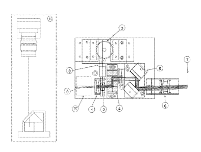
FIG. 1 is a depiction of an apparatus used to determine subjective values of
higher order
aberrations.
FIG. 2 is a schematic drawing of the device such as that of Figure 1 that
shows optical
elements within the apparatus to generate and determine subjective values of
higher order
aberrations.
4
CA 02788672 2012-08-01
WO 2011/100544
PCT/US2011/024523
FIG. 3 Is a graphical representation of data that shows the distribution of
subjects by age
in a clinical study performed with the inventive apparatus.
FIG. 4 Shows a test eye chart.
FIG. 5A Is a graphical representation of data that shows subjective spherical
aberration
measurement results by subject, monocularly with an eye chart.
FIG. 5B Is a graphical representation of data that shows subjective spherical
aberration
measurement results by subject, binocularly with an eye chart.
FIG. 5C Is a graphical representation of data that shows subjective spherical
aberration
measurement results by subject, monocularly with a photo scene.
FIG. 5D Is a graphical representation of data that shows subjective spherical
aberration
measurement results by subject, binocularly with a photo scene.
FIG. 6 Shows a plot of subjective spherical aberration as a function of
objective spherical
aberration measurements. .
FIG. 7 Is a graphical representation of data that shows the net difference
spherical
aberration values by subject.
FIG. 8A Shows a plot of subjective spherical aberration and objective
spherical
aberration measurements for a first subject.
FIG. 8B Shows a plot of subjective spherical aberration and objective
spherical
aberration measurements for a second subject.
DETAILED DESCRIPTION
5
CA 02788672 2012-08-01
WO 2011/100544
PCT/US2011/024523
The invention is an apparatus useful in refining the design of customized
ophthalmic
correction including ophthalmic lenses, methods for using and prescribing
these lenses,
and by refractive surgery. By ophthalmic lenses is meant contact lenses,
spectacle lenses,
intraocular lenses, and inlay or onlay lenses. Preferably, ophthalmic lenses
are contact
lenses. Preferably, the ophthalmic lens is a customized contact lens which
incorporates
subjectively optimized values for higher order aberrations. By refractive
surgery is meant
Lasik, Lasek, PRK and the like.
By higher order aberrations is meant aberrations such as spherical aberration,
coma,
trefoil or other aberrations which are distinct from zero or first order
aberrations such as
spherical and astigmatic error. Preferably, higher order aberrations are
spherical
aberration.
By optical assembly or apparatus is meant an alignable binocular or monocular
optical
system capable of viewing a target at a specified distance including optical
infinity or
near, and introducing a controllable amount of higher order aberration.
Various measurements are used to provide data for vision correction and are
incorporated
into lens prescription and design. Conventional sphero-cylindrical refraction
using a
retinoscope, autorefractor such as the Nidek ARK-700A (Nidek Co., Ltd.,
Gamagori,
Aichi, Japan) or the like yields the patient's low order sphero-cylindrical
corrective
prescription components. This is further refined subjectively using a
phoropter such as
the Nidek RT-5100 (Nidek Co., Ltd., Gamagori, Aichi, Japan) or the like,
yielding the
conventional low order values for spherical power, cylindrical power and
cylinder axis.
Higher order refractive correction is enabled by a wavefront measurement.
Ocular
wavefront data is collected from a patient using a wavefront sensor such as a
COAS
(Wavefront Sciences Inc., Albuquerque, N.M.). This wavefront data is generally
in the
form of Zernike polynomial coefficients, but can also be a set of wavefront
heights at
specified Cartesian or polar coordinates. A preferred system to designate the
Zernike
6
coefficients has been described as the OSA (Optical Society of America)
method, in ANSI
Z80.28.
I he method to design ophthalmic corrections can be used for individuals on a
custom lens basis
or averaged for large populations, or sub-populations. Data obtained by this
method can be
collected to describe the level, range, resolution and tolerance of a
subjective higher order
ophthalmic correction. Obtaining the basic low order objective refractive
prescription can be
determined by the use of a retinoscope, autorefractor, or the like. Acquiring
low order subjective
refractive prescription can be determined by the use of a phoropter or the
like. The objective
higher order aberrations can be acquired by using a wavefront sensor or the
like, while the
subjective higher order refraction is acquired by the apparatus and method of
this invention. The
inventive methods of prescribing and providing customized ophthalmic
corrections take into
account the subjective acceptance of higher order refraction elements.
Spherical aberration is defined as follows. The measurement of the eye's
spherical aberration has
taken several different formats. The first format is derived from optical
engineering in which
aberrations are measured in waves or microns of departure from a reference.
The second format
is attributed to ophthalmic optics in which aberrations are considered a power
error (or
sometimes a power correction), measured in Diopters. Conversion of terms
between the two
communities is facilitated by the radially-dependent power error expression
(Equation 1):
1 MVO
atO = (1)
r
where r is the unsealed pupil radius and W(r) is a radially-dependant wave
aberration function.
The wave aberration function representing spherical aberration can be written
in terms of r as
(Equation 2):
7
CA 2788672 2018-07-27
CA 02788672 2012-08-01
WO 2011/100544 PCT/US2011/024523
(2)
\, max)
where W040 is the wavefront expansion term for spherical aberration and rõ,õ
is the
maximum radial extent. By combining Equations (1) and (2) a relationship
between the
wave aberration and the power error expressions for Spherical Aberration can
be
determined (Equation 3):
dOsA = 44 Wo40r2.
(3)
max
It is sometimes further desirable to express spherical aberration as a
quantity independent
of the pupil radius. This is commonly done in ophthalmic optics by normalizing
(Equation 4) the power error by rmax2
4
- 14724D
MiWe'*
(4)
The units in Equation (4) are commonly reported as mm-3 or D/mm2. This
relationship
was used to convert the spherical aberration values obtained with the
inventive apparatus
into terms of power error, according to ophthalmic convention. Spherical
aberration is
thus defined in units of D/mm2 . Similar relationships between optical
engineering
descriptions and ophthalmic descriptions of other high order aberrations may
be
established in the same manner.
The optical assembly design includes the generation of continuously variable
and
controllable aberrations. Lateral-shift variable aberration plates were
proposed by
Palusinski, et al. [21]. This aberration generating technique is an extension
of the
variable-power lens proposed by Luis W. Alvarez [26] and which is today
commonly
known as the "Alvarez Lens". A pair of mating polynomial plates are placed in
a beam
8
CA 02788672 2012-08-01
WO 2011/100544 PCT/US2011/024523
path. By shifting the plates laterally and in opposite directions to each
other, the relative
shift acts like a differentiation operation on the wavefront passing through
the plates.
The polynomial surface solution that Alvarez found was third-order, which when
shifted
produced a second-order (defocus or power) wavefront. The general solution
found by
Palusinski, et al. describes the surfaces required to generate all of the
third-order
wavefront aberrations. For generation of spherical aberration, the appropriate
polynomial
surface profile T(x, y) is fifth-order and is given by Equation 5:
r
2 3
T (x, y) =k ¨x5 +¨x y2 + xy4 j,
(5)
3
where k is a scaling factor. When shifted along x by equal and opposite
amounts a and -
a, the plates will generate a wavefront aberration Tr(x,y) given by Equation
6:
2 2 1
W (x, y) = 2ka (n +1) (x2 +y2) + 2a2x2 ¨ a- +¨a4
3 5
(6)
= Ka (x2 + y2)2 + 2K a3 (x2 y2 ) 4 Ka3y2 + 1 Ka%
3 5
where ic = 2k(n-1) is a constant for a given design. From Equation (6), it can
be seen that
while primarily producing the desired fourth-order or spherical aberration
wavefront
terms, additional second-order wavefront terms (corresponding to defocus and
astigmatism) are also generated. These additional aberrations are considered
parasitic to
this method of aberration generation and cannot be eliminated entirely,
although they can
be attenuated below an acceptable threshold by the proper design of the
system.
Two approaches can be used to minimize the generation of these parasitic
aberrations and thus improve the quality of the generated spherical aberration
wavefront.
The first approach arises from a simple ratio evaluation of W(x,y), where the
generated
amounts of fourth-order aberration (spherical aberration) and second order
aberrations
(defocus and astigmatism) are compared in Equations (7) and (8):
9
CA 02788672 2012-08-01
WO 2011/100544 PCT/US2011/024523
W
a lc (x2 + y2)2
,A
Wdef 21m' (x2 + y2) (7)
r 2
¨ _
2a2
and
w ica(x2 +y2)2
S'A
4 3 2
Wash .7 Ica y
3y2
= 4a 2
(8)
CO : y = 0 ,
where r2 = x2 + y2 defines the radial extent of the wavefront aperture on the
plates. From
either Equation (7) or (8), the ratio comparison suggests that if the size of
the aperture r is
large in comparison to the shift amount a, then the amount of spherical
aberration
generated will be much more than the amount of parasitic aberrations
generated. In fact,
the ratio of r to a does not need to be very large before the proportional
amount of
generated parasitic aberrations show rapid decline, since it is the square of
this ratio that
is important.
A second approach to reducing parasitic aberration generation involves using
some of the available cubic terms in the surface description T(x, y) to help
balance the
second-order wavefront aberrations. How much of each cubic term should be
added is
not clear by simply examining Equation 6. An analysis, however, has been
performed by
using the minimum variance attribute of Zernike polynomial terms, which can
identify
appropriate amounts of these cubic terms. In this analysis, the surface T(x,
y) is first
converted to an equivalent Zernike surface, and then all terms lower than
fifth-order are
removed. Since the generated wavefront is approximately the derivative of the
surface
description, the wavefront resulting from the surface terms that were removed
would only
have added positively to the overall wavefront variance. By removing the lower
order
CA 02788672 2012-08-01
WO 2011/100544 PCT/US2011/024523
Zernike terms from T(x, y), the resulting surfaces when shifted should
generate a fourth-
order wavefront with a minimum of the residual parasitic aberrations.
Transforming the
surface back to the original Polynomial form gives the below modified version
of
Equation (5), as Equation (9):
(1 5 2 3 2 4 4 3 4 , 1
T(x, y)= k ¨x +¨x y + xy --x --xy- +¨x . (9)
3 15 5 10
It should be noted that the effect of the additional terms in Equation 9 is to
minimize the
influence of the parasitic aberrations across the full range of the lateral
shift. If an
asymmetric range of spherical aberration values is desired, or if the
parasitic aberrations
around the zero spherical aberration value need to be better controlled than
those at the
edge of the range, the cubic terms in Equation 9 should be altered
accordingly.
Because this device is to be used for human vision, the range of spherical
aberration
correction values should represent the range of spherical aberration values
observed in
the population. Using the reported numbers from Porter, et al. for a study on
218 eyes,
the average measured spherical aberration was about +0.14ium of Z4.0 for a
5.7mm pupil.
Converting this into the wavefront aberration term Woo for a 6mm pupil gives a
population average of about +3.9 waves of spherical aberration at k=594nm.
Error bars
shown in the same study also suggest that individual variations can be as much
as 3
waves on either side of the average. To provide a widely-accommodating range
of
variable spherical aberration correction for a general population, the
apparatus should be
designed to generate as much as 7 waves of negative spherical aberration to
about 2
waves of positive spherical aberration.
Another continuous aberration generator involves two counter-rotating Zernike
plates
(Acosta and Bara, 2005). The use of these rotating plates is similar to the
ideas already
discussed, where two mating Zernike surfaces generate variable aberrations
when rotated
with respect to each other. The concept is attractive, since rotary motion is
often easier to
11
CA 02788672 2012-08-01
WO 2011/100544
PCT/US2011/024523
generate than lateral motion. A rotating plate design provides an alternate
solution to the
introduction of non-rotationally symmetric higher order aberrations into the
vision
system. In an alternate aspect, aberrations may be introduced into an optical
assembly
by other means including a spatial light modulator, Fresnel plate, adaptive
optical device,
deformable mirror, digital micro-mirror device and the like.
Some ophthalmic devices can be designed for good on-axis performance only,
however this is not a useful design principle for visual devices where it
desired to allow
the eye to view its environment in a natural way. To design a spherical
aberration
corrector for operation over a moderate visual field (+4 ), the wavefront
correction
should be mapped directly into the pupil of the eye. This condition eliminates
the
appearance of off-axis wavefront errors. This mapping to the pupil of the eye
has been
acknowledged as important for any high-order aberration correction over a
moderate
field.
One of the simplest ways to map a spherical aberration correction into the
pupil of
the eye is to place the aberration generator at the aperture stop of an
optical assembly
such as a lx Keplerian telescope, with the eye placed at the real exit pupil
of the
telescope. With the aberration generator at the stop, the bundle of rays will
pass through
the center of the generator for all field angles. This telescope is designed
to work over a
+4 Field of View. The various fields converge nicely at the exit pupil. By
having a real
exit pupil that is external to the telescope, a lx Keplerian allows efficient
coupling
between the pupil of the eye and the mapped aberration correction. In an
alternate
embodiment, an optical relay system other than a Keplerian telescope may be
used.
Modifications to this basic design can be made for improving the overall
system
performance. Achromatization of the telescope and reduction of wavefront
aberrations
can be handled by appropriate lens design techniques, using the multiple
surfaces of the
telescope as design parameters and considering the optical path through the
aberration
generating plates. Additionally, because the image produced by a Keplerian
telescope is
12
CA 02788672 2012-08-01
WO 2011/100544
PCT/US2011/024523
inverted, proper erection of the image is required if the Gauge is to preserve
orientation
of the object in view. This is typically handled by a prism assembly in the
design of a
standard pair of binoculars, but can be treated equally as well by using air-
spaced mirrors.
The four reflections in the image erection system are usually accompanied by a
deviation
in the line of sight and possibly a change in the interpupillary distance.
Because the
Gauge was designed to preserve the subject's view as completely as possible,
two
additional mirrors in periscope configuration were used to bring the telescope
line of
sight coincident with the subject's line of sight.
Pupil size is also relevant to the present invention. Natural pupils were used
for
the examples provided herein, requiring that the illumination be maintained at
a
consistent level. The pupils were not dilated as a result of the
administration of any
medication. A low light setting for the spherical aberration measurements was
determined
to be best, as the effects of spherical aberration increase with the larger
pupil sizes
induced by lower light levels. The illumination at the vision targets was kept
at about 48
lux. The viewing target illuminance values at this light level were slightly
different for
the two targets because of the dominant white space in the eye chart. After
light
transmission losses through the inventive apparatus of about 50%, the
effective
illuminances at the eye were 5.6 ed/m2 and 3.3 cd/m2 for the eye chart and the
photo
scene, respectively. When the Shack-Hartmann wavefront aberrometer device was
in
use, the lighting was adjusted accordingly, so that similar illumination
conditions were
observed for the objective measurements as well.
While the natural pupil sizes under these conditions ranged from 5mm to 8mm,
any comparison of spherical aberration needed to be made at a common pupil
diameter.
The spherical aberration values were calibrated over a 6mm pupil, and since
these
calibration values were the same for everyone tested, no further conversion
for pupil size
was needed. Since the Shack-Hartmann measurements provided objective
measurements
on spherical aberration that would be useful for comparison, these data sets
were also
scaled accordingly to fit a 6mm pupil.
13
CA 02788672 2012-08-01
WO 2011/100544
PCT/US2011/024523
Optionally, data regarding the topography of the cornea is collected from a
patient using
a device such as the Keratron or Keratron Scout, (Optikon 2000, Rome, Italy).
These
devices function by interpreting the reflection of multiple annular ring
images off of the
cornea. The topographic data is available in several formats. The preferred
format in the
present invention is to depict the cornea as a topographic elevation map. The
topography
data may be utilized in customizing a contact lens design by using such data
to guide
selection of the most appropriate back surface contact lens shape. The
topography data is
also useful for understanding whether the source of ocular aberrations is
corneal or
internal to the eye.
In a preferred embodiment, a customized ophthalmic lens is designed which
includes the
subjectively optimized values for both low order sphero-cylindrical blur and
higher order
aberrations such as spherical aberration. The refinement of and improvement in
the
prescription precision of a proposed final customized ophthalmic lens
incorporates one or
all of these measurements.
Spherical Aberration affects vision in varying degrees depending on viewing
conditions,
accommodation, and individual eye characteristics, but it limits the ability
of the eye to
form a clear image on the retina. Although objective measurements can be made
to
determine the levels of various aberrations in the eye (including Spherical
Aberration),
there are other factors in the human visual system that affect what is "seen".
Hence, a
vision correction approach based purely on objective measurement of the eye's
aberrations does not necessarily correspond to better vision.
The apparatus in the present invention incorporates a design which enables the
user to
vary the amount of spherical aberration introduced into the vision system. The
apparatus
is depicted in Figure 1. A subject looks through the apparatus at a visual
stimulus and is
allowed to adjust the spherical aberration until the best image is perceived.
In an alternate
embodiment, the user interacts with the examiner to determine the best end
point using
14
CA 02788672 2012-08-01
WO 2011/100544
PCT/US2011/024523
psychophysical questions. Adjustment of the apparatus is directly analogous to
the way
that the focus adjust knob on a pair of binoculars allows the user to achieve
the best
image when looking through its eyepiece. Adjustments on the apparatus are made
by
turning two micrometers (one for each eye) until the subject perceives best
vision.
Referring to Figure 2, the optical path for one side or one eye of the
apparatus of the
invention is shown. The amount of aberration is varied by the mechanical
translation of
continuously variable aberration generators (2). These generators are
transparent phase
plates whose presence in an optical path induces spherical aberration. Two
phase plates
are needed in the path of each eye. By translating the plates laterally with
respect to each
other, the amount of induced spherical aberration can be adjusted. A suitable
telescope
arrangement is provided for the subject to view a target at a specified
distance. The
objective of the telescope (1) is separated from the eyepiece (6) of the
telescope.
Aberration induced by the aberration generators (2) is imaged into the pupil
of the eye
(7). Additional mirrors or prisms (4,5) are required to rotate the image to
its original
orientation. A person looking through the apparatus will thus see the same
scene in front
of him or her properly oriented, but with the additional effects of spherical
aberration on
the image. The subject using the apparatus rotates the micrometer knob (8) to
vary the
amount of aberration introduced into the system. In an alternate embodiment,
this could
be an electronic linkage such as a joystick, knob or the like.
The alignment of the apparatus to the subject's eyes is adjusted before each
test using
manual translation stages (3). During alignment, a video camera on the optics
platform is
used to increase positioning accuracy, and the eyes are illuminated for the
camera by
LEDs (9), one LED for each eye. The LEDs emit light in the near infrared
region of the
spectrum, preferably a center wavelength of approximately 865 nm with a Full
Width
Half Maximum bandwidth of 90 nm. After alignment, the LEDs (9) are turned off
and the
camera is removed from the platform. Only standard room lighting and/or
controlled
illumination of the wall chart or scene are used during the test.
CA 02788672 2012-08-01
WO 2011/100544
PCT/US2011/024523
In an alternative embodiment, a beam splitter sends (perpendicularly to the
optical plane)
the image of the pupil to a permanent camera system (10), allowing for
constant
monitoring of pupil location relative to the optical axis of the system. In
this arrangement,
the camera output is displayed on a monitor and the examiner adjusts the
alignment of the
system so that the pupil is centered on the center of the aperture displayed
on the monitor,
and hence the center of the system. The camera can preferably include a system
such as a
PixeLink PL-B741EU-R camera with 23 mm EFL color corrected Schneider compact
lens attached. It is a 1.3 Mega Pixel, monochrome with IR enhancement, USB
connection camera.
Much in the same way that an Eye Care Practitioner uses a patient's subjective
responses
to generate a standard sphero-cylindrical prescription, the apparatus of the
present
invention is a tool used to obtain subjective feedback on how aberrations such
as
.. spherical aberration affect a person's vision and what level of correction
is subjectively
preferred. The apparatus of the present invention allows users to view any
visual stimulus
and adjust the aberration level until the best and most acceptable image is
perceived.
Subjective measurement of spherical aberration by the apparatus and method of
this
invention allows for the collective input of the whole visual system
(including the brain)
.. to decide what can be considered "best vision".
The methods of the invention may be implemented by recording the data acquired
in
testing and measurement with the apparatus of the current invention. The
recorded data
may be provided in any suitable format including written and transcribed or
electronically
captured. The aberration data thus captured may be converted to a format
useful in
generating an ophthalmic correction. This correction may included local power
profile,
phase profile, sag or elevation profile information, and is used to generate
the desired
ophthalmic correction for a lens or refractive surgical application.
Ophthalmic corrections
can be made by this method for the improvement of vision.
16
CA 02788672 2012-08-01
WO 2011/100544
PCT/US2011/024523
The methods of the invention can be embodied as computer readable code on a
computer
readable medium. The computer readable medium is any data storage device that
can
store data, which thereafter can be read by a computer system. Examples of
computer
readable medium include read-only memory, random-access memory, CD-ROMs, DVDs,
magnetic tape, optical data storage devices. The computer readable medium can
also be
distributed over network coupled computer systems so that the computer
readable code is
stored and executed in a distributed fashion.
The invention may be implemented using computer programming or engineering
techniques including computer software, firmware, hardware or any combination
or
subset thereof. Any such resulting program, having computer-readable code
means, may
be embodied or provided within one or more computer-readable media, thereby
making a
computer program product, i.e., an article of manufacture, according to the
invention. The
computer readable media may be, for example, a fixed (hard) drive, diskette,
optical disk,
magnetic tape, semiconductor memory such as read-only memory (ROM), etc., or
any
transmitting/receiving medium such as the Internet or other communication
network or
link. The article of manufacture containing the computer code may be made
and/or used
by executing the code directly from one medium, by copying the code from one
medium
to another medium, or by transmitting the code over a network.
Devices according to the invention may also be one or more processing systems
including, but not limited to, a central processing unit (CPU), memory,
storage devices,
communication links and devices, servers, I/O devices, or any sub-components
of one or
more processing systems, including software, firmware, hardware or any
combination or
subset thereof, which embody the invention as set forth in the claims.
User input may be received from the keyboard, mouse, pen, voice, touch screen,
or any
other means by which a human can input data to a computer, including through
other
programs such as application programs.
17
One skilled in the art of computer science will readily be able to combine the
software created as
described with appropriate general purpose or special purpose computer
hardware to create a
computer system or computer sub-system embodying the method of the invention.
The methods embodied in, for example, the computer instructions on computer
readable media
are used to produce the designs described above. The designs created according
to one of the
methods described above are used to produce lenses. Preferably, the lenses are
contact lenses.
Illustrative materials for formation of soft contact lenses include, without
limitation, silicone
elastomers, silicone-containing macromers including, without limitation, those
disclosed in U.S.
Pat. Nos. 5,371,147, 5,314,960, and 5.057,578, hydrogels, silicone-containing
hydrogels, and the
like and combinations thereof. More preferably, the surface is a siloxane, or
contains a siloxane
functionality including, without limitation, polydimethyl siloxane macromers,
methacryloxypropyl siloxanes, and mixtures thereof, silicone hydrogel or a
hydrogel. Illustrative
materials include, without limitation, aquafilcon, ctafilcon, genfilcon,
lenefilcon, senefilcon,
balafilcon, lotrafilcon, galyfilcon or narafilcon.
Curing of the lens material may be carried out by any convenient method. For
example, the
material may be deposited within a mold and cured by thermal, irradiation.
chemical,
electromagnetic radiation curing and the like and combinations thereof
Preferably, molding is
carried out using ultraviolet light or using the full spectrum of visible
light. More specifically,
the precise conditions suitable for curing the lens material will depend on
the material selected
and the lens to be formed. Suitable processes are disclosed in U.S. Pat. Nos.
4.495,313,
4,680,336, 4,889,664, 5,039,459, and 5,540,410.
The contact lenses of the invention may be formed by any convenient method.
One such method
uses a lathe to produce mold inserts. The mold inserts in turn are used to
form molds.
Subsequently, a suitable lens material is placed between the molds followed by
18
CA 2788672 2018-07-27
CA 02788672 2012-08-01
WO 2011/100544
PCT/US2011/024523
compression and curing of the resin to form the lenses of the invention. One
ordinarily
skilled in the art will recognize that any other number of known methods may
be used to
produce the lenses of the invention.
EXAMPLES
Example 1:
The repeatability of subjective spherical aberration measurements using the
inventive
apparatus of the present invention was evaluated with 14 study subjects. A
total of four
measurement sessions with two days between each session were required for each
study
subject. Subjects were required to be between the ages 18 and 39 and could not
have any
ocular infection or medication. Since the inventive apparatus as used did not
have any
power correction devices, the study subjects additionally had to be emmetropic
either
naturally or by spherical contact lens correction. A Visual Acuity check was
administered prior to participation and a score of at least 20/20-2 in each
eye was required
to continue the study. All subjects who passed the Visual Acuity screening
were also
seated in front of a Shack-Hartmann Aberrometer developed and used at the
University
of Arizona (Jain, 2006) where objective wavefront measurements of each eye
were taken.
If the subject wore contact lenses, the measurements were taken with the
contacts in
place. Significant power error or astigmatism were cause for dismissal of one
or both
eyes from the study.
The distribution of subjects by age is shown in Figure 3 with the average age
being 27 years. By analyzing objective Shack-Hartmann data, the conventional
sphere-
cylindrical power error and astigmatism for each eye was measured along with
the
inherent spherical aberration. The subjects each made a total of 24
measurements with
19
CA 02788672 2012-08-01
WO 2011/100544
PCT/US2011/024523
the inventive apparatus during each of the four sessions. Two vision targets
were used:
an ETDRS eye chart (Figure 4) and a real world photo scene. The two kinds of
targets
provided a variety of spatial frequencies and contrast levels and were
alternated randomly
at 20 feet from the subject. Three measurement iterations were made for each
vision
target and both binocular and monocular measurements were made for each
iteration.
For each measurement session, the subject's task was to adjust the spherical
aberration
until the image seen through the inventive apparatus was subjectively
perceived as the
best image. If the range of acceptable adjustments was wide, the subject was
instructed
to find the midpoint between two positions at which the image degradation was
noticeable. The order of the measurements was randomized within a session, but
the
same 24 measurements were made in every session. The subjects completed the
four
sessions over a period of between 7 to 15 days at various times of the day.
Four measurement conditions were used for each eye: monocular with eye chart,
binocular with eye chart, monocular with photo scene, and binocular with photo
scene.
Each condition had three measurements per session. The average and standard
deviation
of the 12 measurements for each condition and each eye were calculated. Any
data
points beyond 2 standard deviations of the average were removed and the
average and
standard deviation were recalculated for this reduced data set. On average 11
or all 12 of
the data points were used. The results of the subjective measurements are
shown by
subject in Figures 5A, 5B, 5C and 5D. In the Figures 5, data obtained with
left eyes are
denoted by diamonds and data from right eyes are denoted by squares.
A summary of the measurement values for each of the four conditions is given
in Table
1. The standard deviation values represent the repeatability of the device as
used. Table
1 indicates that the average user will choose a subjective spherical
aberration correction
repeatably to within 0.03 D/mm2. For the subjects tested, the average
repeatability across
the four conditions is 0.031 D/mm2, with a standard deviation of 0.015 D/mm2.
Some
subjects showed large deviations, particularly noticeable in the data from
subject B.
20
CA 02788672 2012-08-01
WO 2011/100544
PCT/US2011/024523
Table 1:
Mean Average Mean Std. Maximum Minimum
Subjective SA Deviation Average Value Average Value
Condition (D/mm2) (D/mm2) (D7mm2) (D/mm2)
Monocular Eye -0.048 0.030 0.007 -0.161
Chart
Binocular Eye -0.035 0.030 0.026 -0.086
Chart
Monocular -0.046 0.031 0.010 -0.111
Photo Scene
Binocular Photo -0.033 0.034 0.034 -0.107
Scene
Figure 6 shows the plotted subjective aberration values as a function of
objective
aberration measurements for both the monocular eye chart and monocular photo
scene
conditions for all 24 eyes. A linear regression fit indicates very little
correlation between
the two measurements. Diamonds represent data obtained with the eye chart and
triangles
represent the data obtained with the photo scene. The regression line has a
slope of -0.5
and has been forced to pass through the origin.
The measurements from the inventive apparatus and the Shack-Hartmann
wavefront sensor can be used to determine the net desired Spherical Aberration
for a
given eye. Figure 7 shows the calculated net Spherical Aberration values for
each
subject. Diamonds represent eye chart data and triangles represent photo scene
data. Left
eye data are darker than the right eye data. Inspection of Figure 7 clearly
indicates that
there is a fundamental difference between the objective measurement and the
subjective
measurement of spherical aberration. Here it is clear that the general net or
difference in
spherical aberration is not only non-zero, but is greatly different from
subject to subject.
In the alternative embodiment of the device where a permanent camera system 10
is
employed, the variability in the subjective measurements can be reduced. The
evaluation
of the variability in measurement of subjective spherical aberration was
undertaken in a
study with two subjects, average age of 35 years. The subjects had no ocular
infection or
21
CA 02788672 2012-08-01
WO 2011/100544
PCT/US2011/024523
medication, and were naturally emmetropic (no habitual vision correction).
Objective
Shack-Hartmann data was obtained for each subject, and the conventional sphere-
cylindrical power error and astigmatism was measured along with the inherent
spherical
aberration. The subject viewed the same visual stimulus (real world digital
photographic
scene presented on a digital monitor), both during the measurement using the
objective
Shack-Hartmann aberrometer, and during measurement with the inventive
apparatus.
Measurements were performed with the inventive device with and without the
camera
alignment system in place. The measurements were taken over separate sessions,
over
multiple days, and three subjective measurements of spherical aberration were
recorded
during each session.
A summary of the measurement values for each subject given in Table 2. The
standard
deviation values represent the repeatability of the device as used, and it is
demonstrated
that the standard deviation is significantly reduced with the introduction of
the camera
alignment system.
Table 2:
Condition Subject 1: Subject Subject 2: Subject
Mean 1: Mean Mean 2: Mean
Average Std. Average Std.
Subjective Deviation Subjective Deviation
SA (D/mm2) (D/mm2) SA (D/mm2) (D/mm2)
Without -0.046 0.039 *** ***
camera
alignment
feedback
With -0.044 0.014 -0.087 0.026
camera
alignment
feedback
22
CA 02788672 2012-08-01
WO 2011/100544
PCT/US2011/024523
Figures 8A and 8B show the spherical aberration measurements obtained for the
two subjects, both with the inventive device, as well as with an objective
aberration
measurement system (Shack-Hartmann COAS aberrometer). Squares represent data
obtained with the inventive device, and diamonds represent data obtained
objective
Shack-Hartmann aberrometer. In this case, as in the previous example,
inspection of
Figures 8A and 8B clearly indicates a difference between the objective
measurement with
the aberrometer, and the subjective measurement of spherical aberration with
the
inventive device. Here it is also clear that the subjectively preferred
spherical aberration
is not zero. In addition, we can clearly see that the subjective spherical
aberration is
consistently lower than that obtained from the objectively measured values. It
is also
clear in this as well as the previous example that spherical aberration is
different from
subject to subject.
23