Note: Descriptions are shown in the official language in which they were submitted.
CA 02788686 2012-08-29
68297-1058E
- 1 -
Description
GROUND ENGAGING TOOL SYSTEM
Related Application
This application is a divisional application of Canadian Patent
Application No. 2,667,186.
Technical Field
The field of this invention is ground engaging tools, and more
specifically systems for retaining ground engaging tools on buckets, blades,
and
other work tools.
Background
Many construction and mining machines, such as excavators, wheel
loaders, hydraulic mining shovels, cable shovels, bucket wheels, and draglines
make
use of buckets to dig material out of the earth. The buckets can be subjected
to
extreme wear from the abrasion and impacts experienced during digging. Other
construction and mining machines, such as bulldozers, also include blades or
other
tools that are used to move material such as soil and rock. These blades and
other
tools can also be subjected to extreme wear through abrasion and other wear
mechanisms.
Buckets and blades and other earth-working tools can be protected
against wear by including ground engaging tools (GET). GET is typically
fashioned
as teeth, edge protectors, and other components which are attached to the
bucket or
blade in the area where the most damaging abrasion and impacts occur. For
example, the cutting edge of a bucket can be protected with edge protectors
that
wrap around and protect the edge.
Thus, one purpose of the GET is to serve as wear material and absorb
wear that would otherwise occur on the bucket, blade, or other tool. The GET
can be
CA 02788686 2012-08-29
,
,
68297-1058E
- la -
removed when it has been worn and replaced with new GET at a reasonable cost
to
continue to protect the bucket. Large buckets for draglines and hydraulic
shovels can
cost a considerable amount, so protecting them against wear and the need for
early
replacement is important. It is more economical to wear out and replace the
GET
than to wear out and replace an entire bucket.
,
CA 02788686 2012-08-29
68297-1058
- 2 -
In addition to the purpose of protecting against wear, another
purpose of the GET may be to provide more effective digging. A tooth mounted
on the edge of a bucket, for example, may allow the bucket to penetrate into
the
soil or rock and dig more effectively with less effort.
Many systems have been proposed and used for removably
attaching the GET to buckets and other tools. These systems typically provide
a
pin or other fastener which holds the GET onto the bucket or other tool. Many
problems or disadvantages exist with these known systems. For example, in
some conditions the pins can become stuck inside the GET because of rust or
because other material gets in the space surrounding the pins and causes
binding
or adhesion. As another example of a disadvantage of some known attachment
systems, some require a hammer to drive in the pin or other fastener. On large
GET systems, the hammer required to drive in the pin may likewise be very
large,
and swinging such a large hammer in difficult field conditions can be
objectionable
for the technician.
The pin or other fastener must be very secure and reliable and not
permit the GET to fall off of the bucket or other work tool, even when the GET
is
worn extensively. If the GET falls off of the bucket or blade, it could be fed
into a
crusher or other processing machine and cause damage. Other problems may
also occur if the GET inadvertently falls off the bucket, including extensive
wear of
the exposed area of the bucket left unprotected when the GET fell off which
might
occur before the problem is detected and repaired. The prior art GET attaching
systems have not always held the GET to the bucket or other work tool with
adequate reliability.
In general, the prior art GET attaching systems leave room for
improvement. This invention provides improvements.
Brief Description of the Drawings
FIGS. 1-3 are schematic assembly views representing a GET
attachment system according to the principles of the invention. In FIG. 1, a
post
(normally attached to the adapter) is sliding into the slot of a lock, the
lock being
CA 02788686 2014-05-12
- '
68297-1058E
- 2a -
tool interface; and a retainer bushing having a skirt portion formed with an
internal
surface configured to rotatably receive an external surface of the C-shaped
portion of
the lock, the lock being rotatable along the internal surface of the skirt
portion of the
retainer bushing, and wherein the skirt portion of the retainer bushing
includes a slot,
the slot of the skirt portion of the retainer bushing being substantially
aligned with the
slot of the lock when the lock is in an unlocked position.
Brief Description of the Drawings
FIGS. 1-3 are schematic assembly views representing a GET
attachment system according to the principles of the invention. In FIG. 1, a
post
(normally attached to the adapter) is sliding into the slot of a lock, the
lock being
CA 02788686 2012-08-29
68297-1058
- 3 -
engaged with the tip. In FIG. 2, the post is engaged in the slot, and in FIG.
3, the
lock is rotated to the locking position.
FIG. 4 is a pictorial view of a tip, locking retainer, and lock of a first
embodiment, and the manner in which they may be assembled together.
FIG. 5 is a pictorial view of the tip, retainer bushing, and lock
assembly according to the first embodiment of FIG. 4, with the lock in an
unlocking
position.
FIG. 6 is a side view of the assembly of FIG. 5.
FIG. 7 is a rear view of the assembly of FIG. 5.
FIG. 8 is sectional view of the assembly of FIG. 5, taken along
plane 8-8 indicated in FIG. 7.
FIG. 9 is a pictorial view of the tip, retainer bushing, and lock
assembly according to the first embodiment of FIG. 4, with the lock in a
locking
position.
FIG. 10 is a side view of the assembly of FIG. 9.
FIG. 11 is a rear view of the assembly of FIG. 9.
FIG. 12 is sectional view of the assembly of FIG. 9, taken along
plane 12-12 indicated in FIG. 11.
FIG. 13 is a pictorial view of an adapter according to the first
embodiment.
FIG. 14 is an assembly view of the tip, retainer bushing, lock, and
adapter assembly according to the first embodiment.
FIG. 15 is a sectional view of the assembly of FIG. 14, taken along
plane 15-15 of FIG. 14, with the lock in a locking position.
FIG. 16 is a sectional view of the assembly of FIG. 14, taken along
plane 15-15 of FIG. 14, with the lock in an unlocking position.
CA 02788686 2012-08-29
68297-1058E
- 4 -
FIG. 17 is a sectional view of the adapter of FIG. 15 (the tip, retainer
bushing, and lock have been removed in this view).
FIG. 18 is a sectional view of the tip, lock, and retainer bushing of FIG.
15 (the adapter has been removed in this view).
FIG. 19 is a sectional view of the tip and retainer bushing of FIG. 15
(the adapter and lock have been removed in this view).
FIG. 20 is a sectional view of the tip of FIG. 15 (the adapter, lock, and
retainer bushing have been removed in this view).
FIGS. 21A-E are views of the lock of the first embodiment.
FIGS. 22A-E are view of the retainer bushing of the first embodiment.
Detailed Description
An embodiment of the disclosure relates to a retainer system,
comprising: a lock including: a C-shaped portion defining a slot; and a head
portion
attached to the C-shaped portion and having a first detent, a second detent,
an
annular surface extending between the first detent and the second detent, and
a tool
interface.
FIGS. 1-22 illustrate embodiments and schematic concepts for GET
attachment systems according to the invention. The purpose of these figures is
only
to aid in explaining the principles of the invention. Thus, the figures should
not be
considered as limiting the scope of the invention to the embodiments and
schematic
concepts shown therein. Other embodiments of GET attachment systems may be
created which follow the principles of the invention as taught herein, and
these other
embodiments are intended to be included within the scope of patent protection.
FIGS. 1-3 demonstrate schematically how the GET attachment system
holds the GET onto the bucket or blade, and how it locks and unlocks.
CA 02788686 2012-08-29
68297-1058E
- 5 -
With reference first to FIG. 1, a post, or pin, 10 is illustrated. The post
may be connected or associated with a bucket, blade, or other work tool. In
FIG.
1, only a portion of the post 10 is shown. The portion of post 10 that
connects with
the bucket, blade, or other work tool has been removed from this view for the
purpose
5 of illustrating the manner in which the GET attachment system interacts with
the post.
A lock 20 is also illustrated. The lock 20 includes a slot 21 formed therein
for
accepting a portion of post 10. Lock 20 is received in a lock cavity 41 of a
tip 40.
= The lock cavity 41 is shaped to allow the lock 20 to fit therein, and
also to allow lock
to rotate relative to tip 40. Lock 20 may be placed in lock cavity 41
directly, or a
10 retainer bushing 30 may be disposed around a portion of lock 20, and
disposed
between the lock 20 and lock cavity 41. The
CA 02788686 2012-08-29
68297-1058
- 6 -
purpose and benefits of the optional retainer bushing 30 will be explained in
greater detail hereinafter.
With reference now to FIG. 2, a pictorial view is shown of the post 10
positioned inside of the slot 21 of lock 20. In order for the post 10 to enter
slot 21,
it may be required to pass through a slot 42 formed in tip 40. This will occur
typically by sliding the tip 40 and lock 20 onto a portion of the bucket,
blade, or
work tool and onto post 10. For example, a bucket may include an adapter with
an adapter nose that fits inside of pocket 43 formed in tip 40, in a manner
well
known in this industry. The post 10 may be connected with the adapter. The
post
10 will slide first through slot 42, then into slot 21. Slot 21 need not be a
through
slot as illustrated, but could also be a blind slot similar to slot 42. With
the lock 20
rotated to the orientation relative to the tip 40 that is depicted in FIG. 2,
the post 10
can freely slide into and out of the slot 21. This first position of the lock
20 is the
unlocking position.
With reference now to FIG. 3, the lock 20 has been rotated, in this
case 180 degrees, to a new orientation relative to the tip 40. This second
position
of the lock 20 is the locking position. In the locking position, the opening
of slot 21
is no longer aligned with slot 42. Lock 20 includes a C-shaped portion formed
by
a rear leg 22 joining together a top leg 23 and an opposite bottom leg 24.
Slot 21
is located between the opposing top leg 23 and bottom leg 24. In the locking
position of lock 20 shown in FIG. 3, rear leg 22 blocks the post 10 from
exiting the
slot 21 and sliding out through the slot 42. Thus, with the lock 20 rotated to
the
locking position, the tip 40 is locked onto the post 10 and the bucket, blade,
or
work tool to which the post 10 is connected.
FIGS. 1-3 illustrate schematically the basic functioning of the GET
attachment system. The system may be adapted to many different applications.
For example, the system may be used to attach many different kinds of cutting
edges to blades, tips, edge protectors, side cutters and other accessories to
buckets, tips to compactor wheels, etc. Many variations of the basic designs
shown in FIGS. 1-3 are also possible. Those of ordinary skill in this field
will be
able to adapt the basic parts to suit a particular need in a given
application. For
example, the shapes of post 10, lock 20, and slot 21 may vary widely,
according to
= CA 02788686 2012-08-29
68297-1058
- 7 -
particular needs in a given application. As another example, tip 40 may be
more
broadly defined as a first element 40 which could take the form of a tip for a
bucket or ripper, or could take the form of an edge protector, sidebar
protector, or
other forms of GET. As another example, the structure that connects to post 10
may be broadly defined as a second element, and may take the form of an
adapter permanently or removably attached to a bucket, or may take the form of
a
bucket sidebar or base edge, or any other portion of a work tool such to which
it is
desired to attach GET. As another example, the way in which the lock 20 is
rotated may vary according to needs of the application. The lock 20 may
include a
portion that can be rotated by a tool placed through a bore in tip 40. Or, the
end of
post 10 may be modified so it fits in the slot 21 in a way that the post 10
and lock
rotate together. Then a bore in tip 40 may provide access to the end of post
10, and the post 10 could be rotated causing a corresponding rotation of lock
20.
Many different designs are possible while still utilizing the basic principles
of this
15 attachment system.
FIGS. 4-22 illustrate a first embodiment of a GET attachment system
according to these principles. The first embodiment is also exemplary of many
additional, optional features which may be incorporated to satisfy particular
needs
or provide optional benefits.
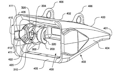
20 With reference first to FIG. 4, a lock 200, retainer bushing 300,
and
tip 400 are illustrated. The tip 400 may be manufactured from steel or any
other
suitable material. The exterior of the tip 400 features surfaces designed to
contact
soil and rock, and absorb or resist the abrasive and impact forces. The
exterior
surfaces can form a relatively sharp front edge 401 in order to permit the tip
400 to
penetrate into the soil or rock and facilitate digging. The tip 400 may also
include
a top portion 402, a bottom portion 403, and side portions 404. In the design
shown in FIG. 4, the top portion 402, bottom portion 403, and side portions
404
meet together and form the front edge 401. The top portion 402, bottom portion
403, and side portions 404 also form an interior adapter receiving cavity 430.
The
adapter receiving cavity 430 is shaped to receive the nose portion of an
adapter
(see FIG. 13). The adapter receiving cavity 430 opens out of the tip 400
through a
rear portion or surface 405. Rear surface is bordered by the top portion 402,
CA 02788686 2012-08-29
=
68297-1058
- 8 -
bottom portion 403, and side portions 404. Several eyelets 406 may be attached
to any of the tip exterior surfaces to facilitate lifting and positioning the
tip 400
during installation.
The tip 400 also includes a slot 410 positioned adjacent a lock cavity
420. Lock cavity 420 is sized to receive the lock 200, and optionally the
retainer
bushing 300 therein. Lock cavity 420 also includes a lock opening 421 (FIG. 6)
which leads from the lock cavity 420 to the exterior of the tip 400. Slot 410
includes side walls 411 and a bottom wall 412. Side walls 411 extend away from
the adapter receiving cavity 430 towards the bottom wall 412 so that bottom
wall
412 is recessed below the surrounding surface of the adapter receiving cavity
430
and slot 410 is generally contained within a side portion 404. Side walls 411
and
bottom wall 412 may define a plane of symmetry which extends parallel to the
slot's longitudinal axis. The longitudinal axis of slot 410 runs from the rear
surface
405 towards the lock cavity 420. The longitudinal axis of slot 410 may also
run
parallel to the direction of movement of the tip 400 relative to the work tool
when
the tip is inserted on or removed therefrom (see arrow A, FIG. 16). The slot
410
opens up to the rear surface 405 on one end, and to the lock cavity 420 on the
other opposite end.
Retainer bushing 300 can be formed from plastic or any other
suitable material. If formed from plastic, it may be desirable to produce it
through
injection molding. Lock 200 can be formed from steel or any other suitable
material. If both tip 400 and lock 200 are formed of steel, then having a
plastic
retainer bushing 300 creates certain benefits. First, a plastic retainer
bushing can
prevent metal-to-metal contact, and the wear mechanisms commonly exhibited
with such contact. Second,' a plastic retainer bushing can help prevent
corrosion
or other processes between the tip and the lock which, over time, could cause
the
lock to seize in the tip and make the lock difficult to rotate. If the lock
cannot be
easily rotated, then the tip removal from the work tool is more difficult.
Third, a
plastic retainer bushing which can deflect more easily than steel can allow a
retaining relationship between the tip and the retainer bushing, and the lock
and
the retainer bushing, as described more fully below. Thus, the choice of
plastic to
form the retainer bushing 300 can be particularly advantageous.
CA 02788686 2012-08-29
68297-1058
- 9 -
With reference to FIG. 4 and FIGS. 22A-E, the retainer bushing 300
includes a slot 310 formed in a substantially circumferential skirt portion
320. The
skirt portion 320 may be conically shaped. Attached to the narrower end of the
skirt portion 320 is a head portion 330. Head portion 330 includes an opening
331, and a flexible tab 332. Tab 332 flexion is promoted by a relief hole 333
formed in the head portion 330.
With reference to FIG. 4 and FIGS. 21A-E, the lock 200 includes a
slot 210. Slot 210 is formed in a C-shaped portion 220 of the lock 200. C-
shaped
portion 220 includes a rear leg 221, top leg 222, and bottom leg 223. Slot 210
is
_ 10 interposed between top leg 222 and bottom leg 223. On top of C-shaped
portion 220 is a head portion 230. Head portion 230 includes two detents 231,
232, formed therein, and an annular surface 233 positioned between the
detents 231, 232. A stopping tab 234 is also formed in the head portion 230.
Head portion also includes a tool interface 235.
FIGS. 5-8 show views of the lock 200 assembled into the retainer
bushing 300, and the retainer bushing 300 assembled into the tip 400. The
lock 200 is rotated to its first position, or unlocking position in each of
these views.
While the lock 200 is in the unlocking position, an adapter or portion of a
work tool
can be inserted into the adapter receiving cavity 430, and a post or other
portion
associated with the adapter will simultaneously slide through slot 410, slot
310,
and into slot 210.
FIG. 6 is a side view which shows retainer bushing 300 and lock 200
projecting through lock opening 421 of tip 400. Tool interface 235 is
accessible by
an appropriate tool to help rotate lock 200 relative to retainer bushing 300
and
tip 400. Any type of suitable tool and tool interface may be used. Preferably,
the
tool includes a male portion, and the tool interface 235 includes a female
portion.
In the unlocking position, tab 332 rests in detent 232. As lock 200 is
rotated relative to retainer bushing 300, tab 332 flexes and comes out of
detent 232. FIGS. 9-12 show the lock 200 rotated to its second position, or
locking position. In the locking position, tab 332 rests in detent 231.
Further
rotation of lock 200 relative to retainer bushing 300 is prevented by stopping
CA 02788686 2012-08-29
68297-1058
- 10 -
tab 234 contacting the head portion 330 of retainer bushing 300. Likewise,
when
the lock is rotated back to its unlocking position, stopping tab 234 will
contact head
portion 330 when tab 332 enters detent 231. This detent and stop system gives
technicians a very good tactile feel for when the lock 200 has been turned to
either
its unlocking or locking position. In part the good tactile feel will come
from the
retainer bushing 300 being made from plastic and tab 332 being flexible enough
to
permit easy rotation, while still providing enough holding power against
detents 231, 232 to hold lock 200 in its unlocking or locking position.
Movement of
the lock 200 from its locking to unlocking position does not require use of a
hammer or other tools as is common with many types of pin retention systems
for
GET. Hammerless systems are increasingly preferred by technicians.
When the lock 200 is assembled into the retainer bushing 300,
structures on each help positively hold the two together. Skirt portion 320 of
retainer bushing 300 defines an internal annular surface 340. Lock 200
includes
an external annular surface 240. Internal annular surface 340 rides against
external annular surface 240 when lock 200 rotates relative to retainer
bushing 300. In this embodiment, the annular surfaces 240, 340 are also
tapered,
resulting in an overall conical shape. Internal annular surface includes ribs
341
formed thereon which extend in a substantially circumferential direction. When
lock 200 is positioned inside of retainer bushing 300, the ribs 341 interfere
with
external annular surface 240. In order to fit lock 200 inside retainer bushing
300,
adequate force must be applied to deflect retainer bushing 300 so ribs 341 can
move past external annular surface 240. Once ribs 341 move past external
annular surface 240, ribs 341 and the retainer bushing 300 can return to a
more
natural, non-deflected position. Ribs 341 will ride against a bottom surface
224 of
C-shaped portion 230, preventing lock 200 from unintentionally slipping out of
retainer bushing 300. Lock 200 is able to rotate inside of and relative to
retainer
bushing 300.
Likewise, when the retainer bushing 300 is assembled into lock
cavity 420 of tip 400, structures on each help positively hold the two
together.
Skirt portion 320 of retainer bushing 300 defines an external surface 350.
.
External surface 350 includes a rib 351 formed in a substantially
circumferential
CA 02788686 2012-08-29
68297-1058
- 11 -
direction. A complementary slot 422 (FIG. 4) is formed in the lock cavity 420
of
tip 400. When retainer bushing 300 is assembled into lock cavity 420, the rib
351
first interferes with lock cavity 420. In order to fit retainer bushing 300
inside of
lock cavity 420, adequate force must be applied to deflect retainer bushing
300 so
that rib 351 slides past the lock cavity 420 surfaces with which it
interferes, until
rib 351 snaps into slot 422. Retainer bushing 300 cannot rotate relative to
tip 400
once installed into the lock cavity 420. The fit of rib 351 into slot 422
prevents
rotation. Also, the lock opening 421 is non-circular. The part of head portion
330
of retainer bushing 300 which fits into the lock opening 421 is also non-
circular.
The fit of the head portion 330 into the lock opening 421 and the non-circular
shape of each also prevents the retainer bushing 300 from rotating relative to
the
tip 400.
Holding together, under normal conditions, the lock 200 to the
retainer bushing 300, and the retainer bushing 300 to the tip 400, has several
advantages. First, during shipping of a replacement tip assembly (including
tip 400, retainer bushing 300, and lock 200) to a jobsite, all three
components stay
together without becoming mixed up or lost. Second, during installation, it is
simple to keep all three components in position relative to one another while
the
tip assembly is slid onto an adapter or other work tool. The installation may
sometimes be conducted in challenging field conditions, including mud and
snow.
Being able to keep all the components together prevents them from being
dropped
into the mud and snow and becoming lost. Further, a technician who may be
wearing protective gloves will not be required to handle the lock 200 and
retainer
bushing 300 which are smaller components and may not be as easily grasped and
manipulated. In general, this feature greatly enhances the ease and speed of
installation.
With reference now to FIGS. 13-17, an adapter 100 is illustrated
which may be used with the tip 400, retainer bushing 300, and lock 200.
Adapter 100 includes a nose portion 110. Nose portion 110 is shaped to fit
inside
of adapter receiving cavity 430 of tip 400. The shape of nose portion 110, and
the
complementary shape of adapter receiving cavity 430, may be selected to suit
any
particular need or application. Several different shapes have been used in
prior
CA 02788686 2012-08-29
68297-1058
- 12 -
GET systems, and any suitable general shape could be selected. The nose
portion 110 includes opposite sloping top and bottom surfaces 111, 112 which
slope towards one another and toward two opposite flat surfaces 113, 114, and
a
flat front surface 115. The nose portion 110 also includes two opposite side
surfaces 116, 117.
Opposite the nose portion 110 is the rear portion 118 which may
include a second adapter receiving cavity 119. In this embodiment, as is known
in
this field, adapter 100 is configured to be received onto a second adapter
that is
mounted to a work tool. The second adapter (not shown) would include a nose
portion that complements the second adapter receiving cavity 119.
On side surface 117 is formed a post 120. Post 120 in this
embodiment is of a generally conical shape. Other shapes could be selected to
suit other designs. Post 120 includes a substantially conical surface 121, and
a
substantially flat end surface 122. As seen in FIG. 17, conical surface 121
defines
a central axis A of the cone shape. Conical surface 121 is formed at a taper
angle f3 of approximately 10-30 degrees, and more preferably about 20 degrees.
The adapter 100 defines a plane of symmetry B as illustrated in FIG. 17 (the
adapter 100 is generally symmetrical about the plane B, discounting the post
120
and related structure). The angle a between plane B and axis A is
approximately 65-85 degrees, and more preferably about 75 degrees.
Adapter 100 also includes a half-annular-shaped cut 130 into the
side surface 117 immediately adjacent and behind (in the direction of rear
portion 118) the post 120. Immediately adjacent and behind (in the direction
of
rear portion 118), the adapter 100 also includes a rail 140 raised above the
side
surface 117. Rail 140 is generally sized and shaped to match slot 410 of tip
400.
FIGS. 15-16 show sectional views of the tip 400, bushing
retainer 300, and lock 200 mounted to adapter 100. FIG. 15 shows the lock 200
rotated to its locking position so the tip 400 cannot be removed from adapter
100.
FIG. 16 shows the lock 200 rotated to its unlocking position so that the tip
400 can
slide in the direction of arrow A off of adapter 100. In each view, rail 140
is shown
positioned in slot 410 where it serves to block dirt and other debris from
entering
CA 02788686 2012-08-29
68297-1058
- 13 -
into slot 410. If dirt and other debris were allowed to enter slot 410, they
may
become impacted and make removal of the tip 400 difficult because post 120
must
slide through slot 410 when the tip is removed.
With central axis A of post 120 positioned at an angle with respect to
the plane of symmetry B, FIG. 15 shows that the rearward most portion of
conical
surface 121 which contacts lock 200 in the locking position is at an angle
near
perpendicular to the direction of force of the tip 400 being pulled straight
off of
adapter 100 (as indicated by arrow A). This helps prevent the force of the tip
400
being pulled off of adapter 100 from twisting the tip 400, deflecting out of
position
lock 200 and causing the lock 200 to slip off of post 120 in a failure.
Positioning
the post 120 in this manner also minimizes the magnitude of the reaction force
that will tend to push lock 200 into the lock cavity 420. The minimized
reaction
forces can be counteracted by compressive forces in the tip 400.
FIG. 19 shows that when positioned in tip 400, retainer bushing 300
has a bottom surface 334 set at an angle y relative to the plane of symmetry B
of
tip 400 of approximately 5 to 25 degrees, and most preferably 15 degrees. Head
portion 230 of lock 200 has a bearing surface 236 that abuts and slides on
bottom
surface 334 of retainer bushing 300. With bottom surface 334 set at this
angle,
the lock 200 rotates between its locking and unlocking position about an axis
approximately parallel to central axis A of the post 120.
Industrial Applicability
The foregoing ground engaging tool system may be used in industry
to provide protection and improved digging ability for buckets, blades and
other
work tools on construction and mining machinery, and other types of machinery.