Note: Descriptions are shown in the official language in which they were submitted.
CA 2789129 2017-04-06
ULTRASOUND IMAGING SYSTEM USING BEAMFORMING TECHNIQUES FOR
PHASE COHERENCE GRATING LOBE SUPPRESSION
Inventors: Jeremy Brown, Robert Adamson, Zahra Torbatian, and Manohar Bance
CROSS REFERENCE TO RELATED APPLICATIONS
[0001] This application,claims the benefit of United States Provisional
Application No.
61/302,242, filed February 8, 2010.
FIELD OF THE DISCLOSURE
[0002] This invention relates generally to ultrasound imaging systems, and
more
particularly to suppressing grating lobes in an ultrasound imaging system.
BACKGROUND
[0003] Low-frequency ultrasound imaging systems are very commonly used in
diagnostic
medicine, and they have been used for over 50 years. New high-frequency
ultrasound
imaging technology offers dramatic improvements in image resolution compared
to these
conventional low- frequency systems. Notwithstanding the increased performance
that is
possible with high-frequency ultrasound imaging, there are many technical
barriers
preventing its widespread use. Some of these barriers may be addressed by
using array-based
systems for high-frequency ultrasound imaging, but fabricating transducer
arrays and the
associated beamformers is more difficult for high-frequency systems since much
smaller
dimensions are involved (e.g., the element to element pitch of the
transducer).
[0004] If an array is fabricated without having sufficiently small
dimensions, large image
artifacts result called grating lobes. Another unsolved problem of existing
systems is that
there is no simple and effective way to suppress grating lobes for ultrasound
imaging systems
that have array transducers with a large element-to-element pitch. One
technique that has
been proposed for suppressing the grating lobes is described in J. Camacho, M.
Parrilla, and
C. Fritsch, "Phase Coherence Imaging," IEEE Trans. Ultrason., Ferroelectr.,
Freq. Control,
Vol.56, No.5, pp. 958-974, 2009. This technique, called "phased coherence
imaging,"
- 1 -
'
CA 02789129 2012-08-07
WO 2011/095896 PCT/IB2011/000430
suppresses grating lobes using phase coherence correction factor receive
beamforming and
synthetic aperture transmit beamforming.
[0005] Synthetic aperture beamforming is not suitable for use in high-
frequency
ultrasound imaging where small vibrations can create phase shifts in the
received signals.
Although synthetic aperture beamforming can produce high frame rates for
generating full
2D images, all of the elements need to be pulsed individually before the
beamforming delays
are inserted. This means that this beamforming technique is susceptible to
image distortion
due to the large amount of time expired during the acquisition of the pre-
beamformed signals.
This image distortion is avoided however when implementing transmit focal-zone
beamforming. Although only one A-scan line can be collected per transmit
event, image
distortion due to small motion artifacts is avoided due to the small amount of
time expired
between beamforming events. Unfortunately, for phase coherence imaging,
transmit
beamforming creates very long pulses in the grating lobe region which, upon
returning to the
array elements, create very long narrow band receive pulses. Consequently,
when phase
coherence correction factors are calculated from the received echoes in the
same temporal
region as the main lobe, there are no longer any random phases present since
all of the long
grating lobe echoes now overlap and for a certain time duration, are virtually
all in-phase.
[0006] Thus, a need exists in the art for improved methods that effectively
shorten the
grating lobe signals in received ultrasound echoes, thereby enabling improved
signal
processing and suppression of grating lobes.
SUMMARY
[0007] The present disclosure addresses long-felt needs in the field of
ultrasound imaging
by providing systems and methods for effectively reducing the temporal length
of transmit
grating lobe signals in received ultrasound echoes. By shortening the grating
lobe signals, the
grating lobes can subsequently be suppressed using signal processing, e.g., by
application of
a calculated phase coherence factor. In this way, the present methods
advantageously make
possible the performance of high-frequency ultrasound imaging with improved
image
resolution.
[0008] Various aspects of the present disclosure provide techniques for
transmit
beamforming to be used with a phase coherence imaging technique that allow
this technique
to be used to suppress grating lobes in a practical, real ultrasound imaging
system. The phase
-2-
CA 02789129 2012-08-07
WO 2011/095896 PCT/IB2011/000430
coherence imaging technique is enabled by using a transmit beamforming
approach that
effectively shortens the time-domain signal of the received echoes. In some
aspects, the phase
coherence imaging comprises sign coherence factor (SCF) weighting. By
producing shorter
time-domain signals, the present methods create a situation in which a smaller
number of the
received echoes overlap upon being received by the imaging transducer making
the SCF
weighting of the phase coherence imaging technique is more effective.
[0009] Various techniques can be used to shorten this time-domain signal.
In one
embodiment, the time-domain signal is shortened by splitting the transmit
signal using a
newly developed "split aperture" technique. In the split aperture technique,
the aperture is
divided into a number of sub-apertures, which are then selectively focused to
obtain
beamformed transmit pulses that shorten the length of the time-stretched
signal in the grating
lobe region. In another embodiment, the time-domain signal is shortened using
a defocused
-probing pulse" technique. Any suitable technique known in signal processing
for shortening
the time-domain signal can be used to enable the use of transmit beamforming
with the phase
coherence imaging technique, which may be implemented in an ultrasound imaging
system.
[0010] Accordingly, various aspects of the present disclosure suppress
grating lobes in
large pitch arrays without requiring synthetic aperture beamforming. Using
this technique for
suppressing grating lobes, it is possible to develop ultrasound imaging
systems having array-
based transducers with a larger pitch. The larger pitch may simplify the
fabrication procedure
of high-frequency transducers significantly, or reduce the number of required
elements in 2D
arrays resulting in arrays that can beam-steer to lager angles with fewer
elements.
BRIEF DESCRIPTION OF THE DRAWINGS
[0011] Figure 1(A) shows a schematic representation of conventional
transducer array
having a linear array geometry. Figure 1(B) shows a schematic representation
of
conventional transducer array having a two-dimensional array geometry. Figure
1(C) shows
a schematic representation of conventional transducer array having an annular
array
geometry.
[0012] Figure 2 shows a schematic representation of beamforming using a
linear array.
[0013] Figure 3 shows a schematic representation of beamforming using a
phased array.
-3-
CA 02789129 2012-08-07
WO 2011/095896 PCT/IB2011/000430
[0014] Figure 4 shows a schematic representation of a geometrical
arrangement of an
array and a desired focal point within an imaging medium.
[0015] Figure 5 shows a schematic representation of receive beamforming.
[0016] Figure 6 shows a comparison of grating lobe echoes for a 64 element
phased
array with 1.25X pitch using (A) transmit beamforming, (B) synthetic aperture
pulsing with
only the central element, and (C) split-aperture transmit beamforming K = 2).
The receive
beamforming delays have been inserted.
[0017] Figure 7 shows proposed transmit and receive apertures according to
various
aspects of the disclosure. Each sub-aperture (K) is focused separately during
transmission (A)
and the echoes are received by all elements (B). One line of the image is
constructed after all
sub-apertures are pulsed.
[0018] Figure 8 shows the geometry of a phased array transducer with
aperture width
(w), and element-to-element pitch (p) focused at focal point (F) on the main
axis. The virtual
curved aperture is used for calculating the distances between grating lobe
point (G) and the
aperture points (Li, L2, and L3) in order to account for the beamforming
delays.
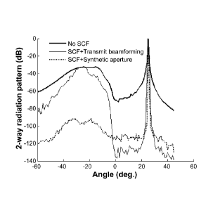
[0019] Figure 9 shows a comparison of grating lobe levels for a 64-element
phased array
transducer with pitch (p)= 1.25k, focused at f/2, and steered at 25 degrees
between no SCF,
SCF-weighted transmit beamforming, and SCF-weighted synthetic aperture.
[0020] Figure 10 shows a comparison or grating lobe levels between split-
aperture
transmit beamforming with different number of splits (K = 1, 2, 4, 8). The
total aperture is a
64-element transducer withf= 40 MHz, pitch (p)= 1.25k, f/2, steered at 25
degrees. As
shown by increasing the K, grating lobe is suppressed more while PRF is
decreased.
[0021] Figure 11 shows the effect of K sub-apertures on grating lobe
suppression for
different element pitches and steering angles for a 64-element phased array
focused at f/2.
The grating lobe level is plotted versus K "splits" (1, 2, 4, and 8) for
steering angles 0, 15, 30,
and 45 degrees at element pitches of a) p = 0.75k, b)p = k, and c)p = 1.25k.
The regular
value of grating lobe with no processing (No SCF) is also plotted for
comparison.
-4-
CA 02789129 2012-08-07
WO 2011/095896 PCT/IB2011/000430
[0022] Figure 12 shows an experimentally measured grating lobe transmit
signal when
the full 64-element aperture is active and focused off to 25 degrees at f/2.
The measurements
were obtained using a 64-element 50 MHz phased array with 1.25X element pitch.
[0023] Figure 13 shows an experimentally measured grating lobe transmit
signal when
half of the aperture is active and focused off to 25 degrees at f/2. The
measurements were
obtained using a 64 element 50 MHz phased array with 1.25k element pitch.
[0024] Figure 14 shows experimentally measured radiation patterns from a 50
micron
wire phantom located at 25 degrees and f/2 when the beam is swept from +35
degrees to ¨ 35
degrees. Figure 14 (A) shows a radiation pattern measured when no SFC is
applied; (B)
shows a radiation pattern when SCF is applied; and (C) radiation pattern when
the aperture is
split in two (K=2). The measurements were obtained using a 64 element 50 MHz
phased
array with 1.25k element pitch.
[0025] Figure 15 shows images generated with a 64 element 50MHz phased
array with
1.25X spacing. The image is of a 50-micron wire phantom located at f/2.5. The
image depth
ranges from 1 mm to 8 mm and the steering angle ranges from +/- 35 degrees.
All images are
displayed with a dynamic range of 60 dB. Figure 15(A) shows an image generated
with no
SCF processing; (B) an image generated with SCF processing but no aperture
splitting on
transmit; and (C) an image generated by splitting the transmit aperture in two
(K=2) and then
applying SCF processing.
DETAILED DESCRIPTION
[0026] The present disclosure relates generally to systems and methods for
effectively
reducing the temporal length of transmit grating lobe signals in received
ultrasound echoes.
The grating lobe signals can then be suppressed using a suitable signal
processing method.
These methods and systems advantageously make possible the performance of high-
frequency and/or 2D ultrasound imaging arrays and provide significant
improvements in
ultrasound image quality.
[0027] A small element-to-element pitch (¨ 0.5k) is conventionally required
for phased
array ultrasound transducers in order to avoid large grating lobes. This
constraint can
introduce many fabrication difficulties, particularly in the development of
high-frequency
phased arrays at operating frequencies greater than 30 MHz. The present
disclosure provides
-5-
CA 02789129 2012-08-07
WO 2011/095896 PCT/IB2011/000430
a novel transmit beamforming technique that enables the performance of high-
frequency
ultrasound imaging.
[0028] In various aspects, the present disclosure provides methods for high
frequency
ultrasound imaging using a split transmit aperture, the method comprising the
steps of:
splitting a transmit beamformer comprising a phased array of N transmit
elements into K sub-
apertures, each sub-aperture having N/K transmit elements; forming a focused
ultrasound
transmit beam from one of the sub-apertures of the transmit beamformer;
transmitting the
transmit signal towards a target along a focused line of sight; obtaining
samples of reflections
of the transmit signal from a target at all N elements of the full transmit
aperture; and
processing the samples to produce an image of the target.
[0029] The present transmit beamforming technique can be used in
conjunction with any
suitable signal processing method, such as for example, phase coherence
imaging with sign
coherence factor (SCF) receive beamforming (Camacho et al., IEEE Trans UFFC,
56(5):958-
974 (2009)), which is capable of suppressing grating lobes in large-pitch
phased-array
transducers.
[0030] In various aspects, methods are provided for splitting the transmit
aperture (N
elements) into N/K transmit elements and receive beamforming on all N elements
to reduce
the temporal length of transmit grating lobe signal. This method eliminates
the need to use
synthetic aperture beamforming in phase coherence imaging. In certain aspects,
the received
signals are weighted by the calculated SCF after each transmit-receive event
to suppress the
grating lobes. After pulsing all sub-apertures, the RF signals can then be
added to generate
one line of the image. Simulated 2-way radiation patterns for different K
values have shown
that grating lobes can be suppressed significantly at different steering
angles. In some
aspects, the present disclosure provides techniques for determining the
optimal transmit sub-
apertures has been developed.
Transducer Arrays
[0031] The structure of an array transducer is similar to that of single
element transducers
in many ways. For example, array transducers are composed of a piezoelectric
sandwiched
between a lossy backing layer and a matching layer(s). The piezoelectric
resonator in an
array transducer, however, is diced to produce a series of individual array
elements. Figures
1(A), 1(B), and 1(C) illustrate the front faces of three common array
geometries. The array
-6-
CA 02789129 2012-08-07
WO 2011/095896 PCT/IB2011/000430
shown in Figure 1(A) is a linear array, the array shown in Figure 1(B) is a
two-dimensional
(2-D) array, and the array shown in Figure 1(C) is an annular array.
[0032] Linear array transducers, such as the example shown in Figure 1(A),
have the
ability to focus the ultrasound energy at any depth in the tissue, along a
line parallel to the
row of array elements. The ability to focus ultrasound energy at any depth in
the tissue makes
linear array transducers more attractive than single element transducers
because the depth of
field is greatly increased. The ultrasound beam is passively focused in the
elevation direction
(perpendicular to the row of elements) using an acoustic lens or geometric
curving. There are
two types of linear arrays: one referred to as a "linear array" and the other
referred to as a
"phased array."
[0033] "Linear arrays" focus the ultrasound beam perpendicular to the array
using a sub-
aperture of array elements. Figure 2 illustrates a group of array elements 201
used to form an
active aperture. The group of array elements are excited using a pattern of
delayed excitation
signals 210 to produce ultrasound wavefronts 220 that are focused along an
image line 222
perpendicular to the array. Additional image lines are obtained by shifting
the active aperture
across the array. A sub-aperture of elements steps across a much larger
aperture, collecting
the parallel A-scans needed to produce a 2-D image. A typical linear array
will have a total
aperture consisting of 256 elements, and use a sub-aperture of 64 elements
with wavelength
spacing A, between the array elements 201.
[0034] Figure 3 illustrates the second version of a linear array, the
"phased array," that
has the ability to steer the ultrasound wavefronts 320. The elements 301 in
the phased array
are excited using a pattern of delayed excitation signals 310 that focuses and
steers the
ultrasound wavefronts 320. Consequently, the image line 322 is no longer
perpendicular to
the array. Additional image lines are obtained by changing the steering angle.
By steering the
ultrasound beam at different angles, a series of A-scans are collected. These
A-scans are used
to generate a sector format image. As a result, phased arrays can have a large
field of view
with a relatively small aperture. Typically, a phased array will use 128
elements with half-
wavelength spacing between the array elements 301. Generally, other than the
smaller
element spacing and aperture size, phased arrays are similar to linear arrays.
[0035] Although annular arrays, such as the example shown in Figure 1(C),
are suitable
for many topical applications in high-frequency imaging, due to their
relatively large element
sizes and low element counts, they do not have the ability to beam steer or
translate the
-7-
CA 02789129 2012-08-07
WO 2011/095896 PCT/IB2011/000430
aperture electronically and therefore need to be mechanically scanned. This
means that the
fixed aperture needs to be relocated in space in order to generate the
parallel "lines of sight"
that make up a 2D image. This creates a larger "effective" aperture limiting
the packaging
size, image scan window, and frame rate. High-frequency linear phased array
transducers can
overcome many of the problems inherent to annular arrays. For example, since
phased arrays
require no aperture translation arrays that are 3 mm or less in total aperture
can be
manufactured.
Transmit Beamforming
[0036] It is convenient to separate an ultrasound beamformer into two
parts: the transmit
beamformer, which generates the sequence of high voltage pulses required to
excite the array
and focus the transmitted energy; and the receive beamformer, which focuses
the received
signals. The operation of the transmit beamformer will be described with
reference to Figure
4.
[0037] Figure 4 illustrates a geometrical arrangement of an array of
elements 1 through n
(in cross-section) that are each separated by a distance d, and a desired
focal point, target
444, within an imaging medium. The lines connecting the transducer array
elements 1
through n to the target 444 show the paths from each element to the target
444. In order to
focus the transducer radiation to a target 444, the path length distances from
each of the
transducer elements 1 through n to the target 444 must be determined. Then the
delay pattern
to apply to signals to the transducer elements 1 through n that is required to
focus the sound
waves to the target 444 can be determined.
[0038] The path length from each of the transducer elements 1 through n to
the target is
calculated based on geometric analysis.
(x, y) =11(y
_ _____________________________________ X2 Eqn. (1)
In Equation (1), /õ is the distance from the nth transducer element to the
desired (x,y) coordinate. If a
constant speed of sound within the medium is assumed, the total time it takes
a pulse to travel from
the nth transducer element to the target is in/co, wherein c, is the assumed
speed of sound within the
medium.
-8-
CA 02789129 2012-08-07
WO 2011/095896 PCT/IB2011/000430
[0039] In order to create constructive interference at the desired focal
distance, a delay
pattern is inserted so that all the pulses from transducer elements 1 through
n arrive at the
target 444 at the same time. These delays are calculated by subtracting the
maximum element
to target flight time given by Equation (2).
\ky -di)2 +X2 \/y2 +x2
ATn y)= _____________________________
Eqn. (2)
Co Co
In Equation (2), AT, corresponds to the excitation delay for element n.
Because a transmit
beamformer can only focus at one depth for each transmit event, the
transmitted wave is allowed to
disperse before subsequent transmit pulses are applied.
Receive Beamforming
[0040] Analogous to the transmit beamforming; the radiation pattern that is
received by
the array can also be focused. The echo from a small object in the body will
arrive back at
different array elements at slightly different times. By delaying the signals
from different
elements to account for the difference in arrival times, the echoes can be re-
aligned so that
they will add coherently. A flow diagram of receive beamforming is shown
schematically in
Figure 5. The transducers (array elements 501) receive the reflected wave 505
and the
signals produced are delayed in a phased pattern using delay devices 550 to
create
constructive interference upon summation at adder 555.
[0041] The receive beamforming process is similar to transmit focusing with
a difference:
in transmit focusing, pulses can only be focused to one depth in the tissue at
a time, whereas
in receive beamforming it is possible to dynamically change the delay pattern
applied to the
echoes as they arc received. In a sense, receive beamforming allows one to
approximate the
radiation pattern of a geometrically shaped transducer whose geometric focus
is sweeping
forward at the speed of sound. Like transmit beamforming, the delay pattern
for the
transducer elements in the array 501 is related to the time of flight between
the element and
the target.
Phased Array Transducers
[0042] Phased array transducers can provide a large field of view with a
small aperture.
However, a small pitch (¨ 0.52) is conventionally required for phased array
transducers in
-9-
CA 02789129 2012-08-07
WO 2011/095896
PCT/IB2011/000430
order to avoid large grating lobes. This produces huge fabrication challenges
for high
frequency phased arrays. The present disclosure provides a novel method for
ultrasound
imaging in which splitting the transmit aperture into K sub-apertures
generates broader band
grating lobe echoes. By applying a suitable signal processing method, such as
for example,
the previously described SCF weighting coefficients, grating lobes can be
significantly
suppressed over a conventional transmit beamforming technique with large pitch
arrays.
Using basic geometric principles, an expression for the optimal aperture
splitting location can
be derived that will produce equally short transmit pulses in the grating lobe
region for the
different sub-apertures. Splitting the aperture into equal-width sub-apertures
closely
approximates the optimal splitting locations for most f-numbers and grating
lobe angles.
According to the present disclosure, the use of a larger number of sub-
apertures (K) can
increase the amount of grating lobe suppression for different pitches and
steering angles. By
increasing the steering angle, greater values of K are required for acceptable
grating lobe
suppression. Therefore, the number of split apertures (K) should be chosen
based on the
steering angle and desired image contrast (grating lobe level) for the
individual application.
The present methods enable high-frequency phased array transducers to be
developed with
larger element-to-element pitch, which simplifies device fabrication
significantly.
[0043] High-
frequency ultrasound imaging (i.e., >20 MHz) can provide high resolution
images of micro-scale tissue structures (Lockwood et al., Ultrasound in
Medicine and
biology, 15(6):60-71 (1996)). The current commercially available systems are
mostly limited
to intravascular and small animal imaging applications. The relatively slow
expansion into
new clinical applications of high-frequency ultrasound can mostly be
attributed to the
difficulties in developing array-based transducers and beamformers operating
at these
frequencies. Conventionally, high-frequency ultrasound imaging systems have
been based on
single-element transducers, which introduce a trade-off between lateral
resolution and depth-
of-field. Mechanical aperture translation is also needed in this case to
capture a full 2D
image. Recent effort has focused on the development of high-frequency annular
and linear
array transducers (Cannata et al., IEEE Trans UFFC, 53(1):224-236 (2006);
Brown et al.,
IEEE Trans UFFC, 51(8):1010-1017 (2004); Brown et al., IEEE Trans UFFC,
54(9):1888-
1894 (2007); Lukacs et al., Proc IEEE UFFC, 105-108 (2005); Ritter et al.,
IEEE Trans
UFFC, 38(2):48-55 (2002); Ketterling et al., IEEE Trans UFFC, 52(4):672-681
(2005);
Snook et al., Proc IEEE Ultrason Symp, 1:865-868 (2003); Hu et al., Proc IEEE
Ultrason
Symp (2009); Sisman et al., Proc IEEE Ultrason Symp (2009)). Although high-
frequency
annular arrays have been shown to provide large depth-of-field and high-
quality images, they
-10-
CA 02789129 2012-08-07
WO 2011/095896 PCT/IB2011/000430
also require mechanical spatial translation, which can limit the frame rate
and packaging size.
The development of high-frequency linear array transducers has proven to
overcome
limitations in frame-rate previously introduced by the mechanical translation,
however, the
field-of-view and packaging size is limited to the size of the full aperture
since linear arrays
can only focus the ultrasound beam perpendicular to the array and do not have
the ability to
beam-steer. In order to overcome the tradeoff between field-of-view and
packaging size, the
development of a high-frequency curvilinear array has recently been reported
(Hu et al., Proc
IEEE Ultrason Symp (2009)). Although arrays such as these are indeed
promising, a more
efficient method of overcoming the tradeoff between field of view and aperture
size can be
achieved with a phased array transducer.
[0044] Phased array transducers have the ability to beam-steer and do not
need to
electronically translate a sub-aperture in order to generate parallel A-scan
lines.
Unfortunately, developing high-frequency phased array transducers has proven
to be
extremely difficult due to the difficulties in fabrication. Specifically, in
order to steer the
ultrasound beam, the element-to-element pitch needs to be significantly
reduced in order to
avoid the introduction of grating lobes (Cobbold, Foundations of biomedical
ultrasound, 437-
450 (2007)). For example, at 50 MHz and a steering angle of 45 degrees, in
order to push the
grating lobe angle to 90 degrees, the element pitch needs to be reduced to 15
microns
(Ziomek, Fundamentals of acoustic field theory and space-time signal
processing, 528-532
(1955)), which is beyond most current fabrication capabilities. For this
reason, many studies
have investigated different methods for grating lobe suppression to allow
design of phased
arrays with larger pitch (Rew et al., Electronics letter, 19(19):1729-1731
(1993); Gavrilov et
al., IEEE Trans UFFC, 44(5):1010-1017 (1997); Wang et al., IEEE Trans Antennas
and
Propagation, 56(6) (2008); Ustuner et al., U.S. Pat. No. 7,207,942 B2 (2007);
Li et al., IEEE
Trans UFFC, 50(2):128-141 (2003)).
Grating Lobe Suppression
[0045] Any suitable signal processing method for suppressing grating lobes
can be used
according to the present disclosure, including methods currently described in
the literature for
suppressing grating lobes in large-pitch phased array transducers. According
to various
aspects of the present disclosure, the processing method comprises weighting
the samples by
a calculated phase coherence factor, which can comprise SCF.
-11-
CA 02789129 2012-08-07
WO 2011/095896 PCT/IB2011/000430
[0046] One suitable signal processing method focuses primarily on
manipulation of the
array structure by removing the periodic pattern of the elements (Rew et al.,
Electronics
letter, 19(19):1729-1731 (1993); Gavrilov et al., IEEE Trans UFFC, 44(5):1010-
1017 (1997);
Wang et al., IEEE Trans Antennas and Propagation, 56(6) (2008)). In these
methods, some
elements are removed randomly until an under-sampled portion of the aperture
remains,
resulting in a "sparse array." However, there is a reduction in transmit
intensity of sparse
arrays because of the low number of elements, which results in a low signal-to-
noise ratio
(SNR). The other major drawback to sparse arrays is that the level of the side
lobes will
increase because the average side lobe to main lobe power is equal to 1/N
(Cobbold,
Foundations of biomedical ultrasound, 437-450 (2007)).
[0047] According to one aspect of the present disclosure, the signal
processing method
can comprise a method for suppressing grating lobes that focuses on processing
the echoes
received by each element to suppress grating lobes. According to these
methods, a weighting
factor (between 0-1) is calculated based on a specific characteristic of
echoes such as time-
shift (cross-correlation (Ustuner et al., U.S. Pat. No. 7,207,942 B2 (2007)))
or the receiving
direction of the echoes (FFT (Li et al., IEEE Trans UFFC, 50(2):128-141
(2003))). The
echoes are multiplied by the computed weighting factors and added to generate
one line of
the image. Although these methods are promising, they have the inherent
drawback of high
computational cost in calculating the weighting factors, which makes them
unsuitable for
high frame-rate imaging.
[0048] According to one aspect of the present disclosure, the signal
processing can
comprise a low-computational power method called "phase coherence imaging" for
grating
lobe suppression in large pitch arrays (Camacho et al., IEEE Trans UFFC,
56(5):958-974
(2009)). In this method, the phase of delayed echoes received by each element
is detected and
then a weighting factor is defined based on the standard deviation of the
phases at each time
point. At the focal point, all of the element echoes will be in phase, so the
standard deviation
of their phases is close to zero, which results in a weighting factor close to
one. For the
grating lobes, the phases of the echoes are not always perfectly in phase, so
the standard
deviation of them in certain cases is greater than zero, resulting in a lower
weighting factor.
This method is mostly effective for synthetic aperture beamforming where the
received
grating lobe echoes are broadband. Essentially, after the transmit beamforming
delays are
reconstructed along with the receive beamformed A-scans, time domain points
that are
similar to the main lobe are either zero or random in phase over a large
number of the
-12-
CA 02789129 2012-08-07
WO 2011/095896 PCT/IB2011/000430
elements. This creates a spread in the standard deviation of phases and
therefore the broad
bandwidth of the received echoes is the primary reason that the standard
deviation of the
phases is non-zero.
Shortening Transmit Grating Lobe Signals
[0049] The present disclosure provides novel methods for generalizing the
phase
coherence imaging method for suppressing grating lobes of phased array
transducers when
using transmit beamforming, where long narrowband grating lobe echoes are
inevitable. The
present disclosure relates generally to systems and methods for effectively
reducing the
temporal length of transmit grating lobe signal in received ultrasound echoes.
The benefits of
grating lobe suppression through signal processing are significantly improved
by decreasing
the time-domain signal of the grating lobe signal prior to signal processing.
Using these
methods, phased arrays with element pitches much larger than one-half of the
ultrasound
signal wavelength are possible. Therefore, the fabrication of high-frequency
phased arrays is
significantly simplified, and the number of elements required in 2D arrays is
reduced.
[0050] A special case of phase coherence imaging is calculating sign
coherence factor
(SCF) as the weighting factor. In this method, the sign bit of received echoes
by each element
(be) at each time point is considered (Camacho et al., IEEE Trans UFFC,
56(5):958-974
(2009)). At each time point, the standard deviation of sign bits (a) is
calculated and the SCF
is defined as follows in Equations (3A) and (3B):
SCF a = Eqn. (3A)
- 2
1 N
Eqn. (3B)
N
Where a? 1 adjusts the sensitivity of the correction factor and N is the
number of elements.
Although it has been shown that different "a" values can actually further
suppress grating
lobes, for the remainder of this article we assume an a value equal to 1. At
the focal point,
where all of the received echoes are in phase, the sign bits of all elements
are the same,
resulting standard deviation close to zero and as a consequence the weighting
factor equal to
one. When transmit beamforming is used, the signal in the grating lobe region
in a one-way
radiation pattern is very long in the temporal domain. Therefore, when
considering echoes
-13-
CA 02789129 2012-08-07
WO 2011/095896 PCT/IB2011/000430
received by the array elements from the grating lobe region, they are also
very long and
narrow-band. Even after the beamforming delays are inserted, these long
grating lobe echoes
overlap and if the sign bit is considered in the same temporal region as the
main lobe signal,
the signals are all similar in phase and hence the weighting factor in this
case is also
approximately equal to 1.
[0051] By shortening the time-domain of the grating lobe signals, the
present method
makes possible the performance of high-frequency ultrasound imaging at greater
image
resolution. Using the present methods, it is possible to perform the method at
ultrasound
frequencies greater than 30 MHz. In some aspects, the method can be performed
at
frequencies of 20 MHz, 30 MHz, 40 MHz, or 50 MHz. The present methods are also
applicable to low frequency ultrasound, such as at frequencies below 20 MHz.
[0052] Figure 6(A) shows an example of the individually received echoes
from the
grating lobe region resulting from transmit beamforming. The signals are for a
64 element
phased array with an element pitch of 1.252 steering at an angle of 25 degrees
and focusing
to f/2. The pulse echoes were simulated using the two-way impulse response
method (San
Emeterio et al., J Acoust Soc AM, 92(2):651-662 (1992)). The sum of the one-
way transmit
pulses in the grating lobe region is calculated and then used as the point
source for the
received echoes. The bandwidth of the two-way pulse echo in the main lobe
region however
is approximately 50%. Figure 6(A) clearly shows how the overlapping echoes
from the
grating lobe region are stretched out in the time domain. Because they are
virtually all in
phase over a temporal window similar to the main lobe, a large weighting
factor results. This
prevents SCF from effectively suppressing grating lobes when transmit
beamforming is used.
[0053] The SCF method can, however, effectively suppress grating lobes when
synthetic
aperture transmit beamforming is used. The main difference is that for
synthetic aperture,
only one element is pulsed at a time which results in broadband echoes
returning to the array,
even from the grating lobe region. After the receive beamforming delays are
inserted, these
broadband echoes have very small overlap in the time domain resulting a large
sign-bit
standard deviation since many of the signals are zero (random phase) at any
given moment in
time. This produces a very low SCF weighting coefficient. Figure 6(B) shows an
example of
the received grating lobe echoes from a 64 element, 1.25X pitch phased array
steering to 25
degrees when pulsed with a single dcfocused element (clement 32). In this
case, it can clearly
be seen that the echoes are predominately not in phase in the same temporal
region as the
-14-
CA 02789129 2012-08-07
WO 2011/095896
PCT/IB2011/000430
main lobe signal. In fact, the received signals are so broad band that most
are zero (random
phase).
[0054] As addressed above, synthetic aperture beamforming has significant
disadvantages because many transmit events are required before the signals are
beamformed.
Therefore, the pre-beamformed signals are susceptible to phase distortions
from small tissue
movements during the relatively long pulsing sequence. High-frequency arrays
are
particularly sensitive to small tissue movements since the wavelengths are
extremely short
and therefore a small amount of tissue motion results in a large change in the
echo phase.
Transmit beamforming avoids these phase distortions because long pulsing
sequences
between beamforming are not required. The methods of the present disclosure
advantageously shorten the time-domain of grating lobes without requiring the
use of
synthetic aperture beamforming.
[0055] If transmit beamforming is desired for large pitch phased arrays
however, a new
method for increasing the effectiveness of the SCF is needed. Since the
underlying problem
in applying SCF to an array using transmit beamforming is the long time-
stretched signal
resulting in the grating lobe region, a method that produces shorter time-
domain signals
should result in a smaller number of the received echoes overlapping upon
receive and hence
the SCF weighting technique should be more effective. Since the length of the
time domain
signal is approximately equal to the difference in arrival times between the
closest and
furthest elements in the array, we are proposing a very simple solution of
splitting the
transmit aperture into K sub-apertures, where K potentially varies from 2 to N
(number of
elements) in order to shorten the length of the time-stretched signal in the
grating lobe region
(Figure 7(A)). It is desirable to keep K as low as possible in order minimize
the total amount
of time expired before the signals are beamformed. Again, this reduces the
amount of phase
aberration between pre-beamformed signals due to tissue motion.
[0056] According to the present disclosure, the number of sub-apertures (K)
can be any
value such that the transmit aperture is capable of producing a focused beam.
In certain
aspects, K is an integer between 2 and 16. In further aspects, K is between 2
and 10. In yet
further aspects, K is 2.
[0057[ Any suitable element-to-element pitch can be used according to the
present
methods. According to certain aspects, the element-to-element pitch is greater
than 0.52. In
further aspects, the element-to-element pitch is 0.5X. In certain aspects the
element-to-
-15-
CA 02789129 2012-08-07
WO 2011/095896 PCT/IB2011/000430
element pitch is 0.75X. In certain aspects the element-to-element pitch is 1X.
In certain
aspects the element-to-element pitch is 1.25X.
[0058] Any suitable steering angle can be used according to the present
methods,
depending on the value of the corresponding element-to-element pitch.
According to various
aspects, the steering angle can be from 1 to 45 degrees. In certain aspects,
the steering angle
is 10 degrees. In further aspects, the steering angle is 15 degrees. In
further aspects, the
steering angle is 20 degrees. In further aspects, the steering angle is 25
degrees. In further
aspects, the steering angle is 35 degrees. In further aspects, the steering
angle is 40 degrees.
In further aspects, the steering angle is 45 degrees.
[0059] According the present disclosure, any suitable array size (N) can be
used, for
example and without limitation, the array size (N) can be between 16 and 512.
[0060] Unlike synthetic aperture bcamforming which uses defocused pulses,
the methods
of the present disclosure use transmit focusing along different lines of
sight. In this case, N/K
elements are pulsed with transmit focusing delays and all N elements
participate in the
receive aperture (Figure 7(B)). After each transmission, the SCF is calculated
based on the
time-shifted echoes and is used to weight the beamformed signal. After K
transmit events, all
weighted echoes are added together to generate one line in the image. Again,
by reducing the
size of the aperture to N/K elements for transmission, the grating lobe signal
is shorter due to
the reduced difference in distance between the closest and furthest elements
in the transmit
aperture. This reduction in overlap for the grating lobe echoes results in a
much lower SCF.
Figure 6(C) shows an example of the received grating lobe echoes resulting
from a split
transmit aperture of 32 elements after the receive beamforming delays have
been inserted on
all 64 receive elements K = 2). Similar to Figure 6(A) and 1(B), this
simulation is for a
phased array with an element pitch of 1.25X, a steering angle of 25 degrees,
and a focal
depth of f/2. It can clearly be seen from this plot that there is much less
phase coherence
between the echoes for the split transmit aperture technique and will
therefore result in a
much lower SCF weighting factor.
[0061] According to various aspects of the present disclosure, the optimal
transmit
apertures are determined in order to achieve equally short temporal transmit
pulses between
sub-apertures in the grating lobe region. Experimental simulation results have
showed that
approximately equal-width sub-apertures (1/2*w for K = 2, Vt*w for K = 4,
etc.) produce
approximately equally short grating lobe transmit pulses or rather equal
differences in
-16-
CA 02789129 2012-08-07
WO 2011/095896
PCT/IB2011/000430
distance between the closest and furthest element in the sub-aperture. An
expression is
derived below for determining where to split the transmit aperture in the case
of K = 2 in
order to obtain equal length grating lobe signals from both transmit
apertures. The optimal
position occurs when the difference in distance between the closest and
furthest elements in
each sub-aperture are equal. Figure 8 shows the geometry of a phased array
where "0" is the
origin of the x-z Cartesian plane. It has been assumed that the focal point
(F) is on the main
axis and the grating lobe (G) is located on the same radius (R) at an angle
from the central
axis calculated by Equation (4) (t'Hoen, IEEE Ultrason Symp Proc, 94-95
(1982)).
0 = sin' (¨A) Eqn. (4)
P
In order to account for the effect of an array of elements with transmit
bcamforming delays
inserted in order to focus to F, a virtual curved aperture is considered for
the rest of the
derivation. Li, L2, and L3 are the distances between the grating lobe point
(G) and the points
on the virtual curved aperture. In order to have transmit pulses with the same
length in the time
domain for both splits, the equality of distances defined in (3) should be
satisfied.
L3 ¨L2 =L2 ¨L1
L2 = (LI + L3) Eqn. (5)
2
where the distances between grating lobe and the virtual aperture points are:
Li =11(R sin 0 ¨ ¨3/41)2 + (R cos 0)2
2
L3 = II(R sin (9 ¨ (¨ ¨11)))2 + (R cos 0)2 Eqn. (6)
2
L2 = 11(R sin 0¨ x0)2 + (R cos 0¨ z0)2
where "w" is the total array aperture and (x0,z0) is point on the virtual
curved aperture. It can be
shown that for L2, z0 can be replaced as a function of x0 reducing L2 to:
11- w
L2(xo ) = (R sin 0 ¨ X0)2 (R cos 0 ¨ (R ¨2 ..i1R + (¨)2 ¨ x02))2 Eqn. (7)
2
-17-
CA 02789129 2012-08-07
WO 2011/095896
PCT/IB2011/000430
and LI and L3 are simply L2( -)and L2(--w ) respectively. The following
derivation is based
2 2
on the assumption that R>> ¨w which is a reasonable assumption at f-numbers
greater than 2.
2
By squaring the right side of Equation (5), we obtain:
2
(11(R sin 0 ¨ / ))2 + (R cos 0)2 + li(R sin 0 ¨ (¨ 1 ))2 + (R cos 0)2 )2 R2
cos2 Ow
2 2 R2+ 4 Eqn. (8)
4w2
(R 2 - )
4
The approximation is based on the first-order Taylor approximation of a
square:
Vx2 +a = x + Eqn. (9)
2x
By squaring the right side of Equation (5), and again using the Taylor
approximation in
Equation (9), we obtain the expression:
(Rsin0 ¨x0)2 + (R cos0¨(R _R2 +( )2 ¨x02))2
11
2
Eqn. (10)
(1 ¨ cos (9)x2o ¨ (2R sin 0)xo + (cos (9w2¨ + R2 )
4
The equality of Equation (8) and Equation (10) therefore results in
w2
, R2 cos2 0 __
(1 ¨ cos 0)x2 0 ¨ (2R sin 0)xo + (cos 0 w
, w2 4 ) = ID Eqn. (11)
4
(R_)
4
By solving the root of Equation (11) and substituting R = Ew and w = Np, the
expression for
"xc," is obtained, which is the element at which to split the aperture in
order to obtain equal-
length time-domain signals.
F sin 0 ¨ 1F2 sin 9 -1 - COS 0
2 ()(
1,COS 0 F2 cos2 9)
4
=( 4 __ (4F2-1) __ ))(NP) Eqn. (12)
(1¨ cos 0)
-18-
CA 02789129 2012-08-07
WO 2011/095896 PCT/IB2011/000430
The term x, is a function of (N, F, p) . Generally, however the expression for
x, approaches
zero at very large and very small grating lobe angles (i.e., the aperture is
split at the central
element). Intuitively, one can visualize a pulse arriving at the virtual
curved aperture either
from 90 degrees or from the main axis. These pulse echoes will "see" a
symmetric aperture
where the difference between the closest and furthest elements in each sub-
aperture (split at x.
= 0) are the same. In fact for most grating lobe angles, f-numbers, and
element pitches, x0 is
typically very close to zero when K = 2. In this manner, the transmit
beamforming technique is
simplified making it easy to implement into a real time system. Similar
expressions can easily
be obtained for splitting the aperture into 3, 4, 5, or any other suitable
value based on these
simple geometric principles. Generally, however, splitting the aperture into
equally sized sub-
apertures closely approximates the calculated value.
[0062] Using the
"equal aperture split" generalization, the "x" location that should be
chosen for spit-aperture transmit beamforming is:
.fl WK ¨2
x = (/ +1)¨ ¨ 0 i < __
K2 2
xi ¨ X(K 2) Eqn. (13)
X(K) =0 if (K -1) is odd
2
where, i is element number, K is the number of splits, w is the width of
aperture, and xi is the
coordinate of element based on the geometry in Figure 8. It should be noted
however that the
derivation of Equation (12) was based on an approximation that is valid for f-
numbers greater
than approximately 2. In various aspects, f-numbers greater than 1 are
suitable for use with the
present methods. In certain aspects, a focal dept of f/2 can be used.
[0063] By
shortening the time domain of the grating lobe signals as described above,
suppression of the grating lobes is dramatically improved using signal
processing methods. In
various aspects, the grating lobe signal can be suppressed by between 20 dB
and 60 dB. In
certain aspects, the grating lobe signal can be suppressed by 20 dB. In
certain aspects, the
grating lobe signal can be suppressed by 40 dB. In certain aspects, the
grating lobe signal can
be suppressed by 60 dB.
-19-
CA 02789129 2012-08-07
WO 2011/095896 PCT/IB2011/000430
Ultrasound Imaging System
[0064] In various aspects, the present disclosure provides a system for
high-frequency
ultrasound imaging using a split transmit aperture, the system comprising: an
imaging array
comprising a phased array of N transmit elements, the transmit elements
divisible into K sub-
apertures, each sub-aperture having N/K transmit elements; a transmit
beamformer coupled
to the imaging array, wherein the transmit beamformer is configured to apply
energy
selectively to the elements of each of the sub-apertures to focus a transmit
signal from the
sub-aperture towards a target; a receive beamformer coupled to the imaging
array, wherein
the receive beamformer is configured to sample a signal received by the
imaging array at
each of the N elements thereof; and processing circuitry configured to receive
the sampled
signal and compute an imaged based thereon.
[0065] In various aspects, a computer controls the transmit beamformer. The
transmit
signals can comprise pulsed signals. The transmitted signals reflect off of
tissue structures (or
target areas) and arc received by the elements in the imaging array. These
signals received at
the imaging array can be directed through amplifiers that are connected
between the elements
of the imaging array. The digital data is transferred back to the computer for
image
processing.
[0066] According to the present disclosure, the number of sub-apertures (K)
in the system
can be any value such that the transmit aperture is capable of producing a
focused beam. In
certain aspects, K is an integer between 2 and 16. In further aspects, K is
between 2 and 10.
In yet further aspects, K is 2.
[0067] Any suitable element-to-element pitch can be used according to the
present
systems. According to certain aspects, the element-to-element pitch is greater
than 0.5X. In
further aspects, the element-to-element pitch is 0.5X. In certain aspects the
element-to-
element pitch is 0.75X. In certain aspects the element-to-element pitch is 1X.
In certain
aspects the element-to-element pitch is 1.25X.
[0068] Any suitable steering angle can be used according to the present
system,
depending on the value of the corresponding element-to-element pitch.
According to various
aspects, the steering angle can be from 1 to 45 degrees. In certain aspects,
the steering angle
is 10 degrees. In further aspects, the steering angle is 15 degrees. In
further aspects, the
steering angle is 20 degrees. In further aspects, the steering angle is 25
degrees. In further
-20-
CA 02789129 2012-08-07
WO 2011/095896 PCT/IB2011/000430
aspects, the steering angle is 35 degrees. In further aspects, the steering
angle is 40 degrees.
In further aspects, the steering angle is 45 degrees.
[0069] According the present disclosure, any suitable array size (N) can be
used, for
example and without limitation, the array size (N) can be between 16 and 512.
Applications
[0070] The presently described methods can be used for any suitable
application, such as
for example endoscopy, which includes without limitation, laproscopic, itra-
cardiac, and
surgical guidance imaging, and the like. Thus, the high-frequency ultrasound
imaging system
described herein can improve diagnostics, interventions, and therapeutic
monitoring of a
variety of disorders. This new diagnostic imaging approach can improve the
objectivity and
quality of diagnosis in this field of medicine, allowing physicians to apply
more precisely
targeted interventions.
EXEMPLARY ASPECTS
EXAMPLE 1
SCF in Combination with Transmit Beamforming and Synthetic Aperture
[0071] The usefulness of SCF method for grating lobe suppression, is
dependent on the
temporal length of the transmit pulse in the grating lobe region. The shorter
the transmit
pulse, the more effective the SCF method is for grating lobe suppression. In
Figure 9, 2-way
radiation patterns for a 64-element phased array transducer with element pitch
(p) = 1.25k,
focused to f/2, steered at 25 degrees are shown. One radiation pattern has no
SCF weighting
and this is compared with SCF-weighted transmit beamforming K = 1) and SCF-
weighted
synthetic aperture beamforming. It can clearly been seen that SCF weighting is
not very
effective for suppressing grating lobes when transmit beamforming is used,
however, it
suppresses the grating lobes in synthetic aperture beamforming more than 50
dB. Again the
underlying reason for the big difference in effectiveness between the two
transmit techniques
is seen in Figure 6(A) and 6(B). In Figure 6(A), the grating lobe echoes in
transmit
beamforming are all in the same phase whereas they are not for synthetic
aperture (Figure
6(B)). For transmit beamforming, a weighting factor nearly equal to one
results in the grating
lobe region since all of the sign bits are the same at all time points.
-21-
CA 02789129 2012-08-07
WO 2011/095896 PCT/IB2011/000430
[0072] By splitting the aperture into two equal sub-apertures K = 2), the
signals arriving
from the grating lobe region are much shorter and as a result, the received
echoes are not
completely phase coherent after the receive beamforming delays are inserted.
Figure 6(C)
shows the received echoes on all 64 elements and it can clearly be seen that
the sign bits are
not all similar for the received signals and therefore the SCF weighting
factor is low. Similar
to the received signals in synthetic aperture beamforming, many of the signals
are zero or
random in phase at any given time point. By splitting the transmit aperture
into more equal
width sub-apertures, the length of the grating lobe signals becomes even
shorter resulting in
an even lower SCF weighting factor.
EXAMPLE 2
Effect of Aperture Splitting
[0073] Figure 10 shows 2-way radiation patterns for a 64-element phased
array
transducer with pitch (p) = 1.25k, focused at f/2, and steering angle of 25
degrees. Radiation
patterns arc compared between transmit apertures with no weighting (No SCF),
with SCF-
weighting and no splitting (K = 1), and SCF-weighting + splitting (K = 2, 4,
8). This
simulation clearly shows that split-transmit apertures are very effective in
grating lobe
suppression with SCF weighting factors (e.g., 20 dB grating lobe suppression
is achieved
with K equal to only 2). By increasing K, smaller apertures are pulsed during
transmission
resulting in shorter grating lobe echoes and as a result have less phase
coherence. However,
the frame-rate is decreased by increasing K and more transmit events are
required before the
signals are beamformed, potentially resulting in phase aberrations.
[0074] For a more quantitative evaluation of the effectiveness of the split-
aperture
method on grating lobe suppression, 2-way radiation patterns of 64-element
transducers with
different pitches (0.752, k, 1.25 X) steered at various angles (0, 15, 30, and
45 degrees)
focused at f/2 are processed by SCF-weighting and different split-transmit
apertures (K = 1,
2, 4, 8). For each pitch value and steering angle, the grating lobe level is
plotted versus split-
aperture (K) in order to observe the effect of increasing K on grating lobe
suppression. Four
different steering angles for each pitch value are shown on each graph in
Figure 11,
summarizing the results forp = .75k, k, and 1.252. respectively. At each
angle, the grating
lobe suppression increases by increasing the number of split-apertures (K). We
can see from
Figure 11 that at large steering angles (30, 45 degrees) the amount of grating
lobe
-22-
CA 02789129 2012-08-07
WO 2011/095896 PCT/IB2011/000430
suppression increases by approximately 20 dB for all element pitches (0.75X,
12,, and
1.25X) by simply splitting the transmit aperture in half (K = 2).
[0075] The important aspect of these graphs is that the K value should be
chosen based
on the range of steering angles in a given application and transducer pitch.
For example in the
case of p = 1 k, Figure 11(C) shows that with K = 1 (SCF-weighting with no
splitting), it is
possible to suppress the grating lobe to less than -60 dB below the main lobe
at a 15 degree
steering angle, while for a 45 degrees steering angle, K must be increased to
8 in order to
suppress the grating lobes to -60 dB.
[0076] As described above, increasing the K decreases the frame rate, which
is usually
undesirable. Therefore, a split aperture technique that could be used to
recoup some of the
decreased frame rate would be to gradually increase the "K" value as the A-
scan lines shift to
larger steering angles. As shown in Figure 11 even with an element pitch of
1.25X, SCF
weighting will suppress the grating lobe level approximately 60 dB below the
main lobe at a
zero degree steering angle with K = 1 (no aperture splitting). However, by the
time 45
degrees of steering is reached, 8 sub-apertures with transmit focusing are
required to maintain
the same amount grating lobe suppression.
[0077] An alternative technique that could potentially avoid the need to
use multiple
transmit pulses per A-scan line is to send out a broad defocused "probing
pulse" from the
entire aperture in order to generate a map of SCF values for all space. In
order to defocus the
pulse, beamforming delays corresponding to a virtual point source behind the
array is
required (Lockwood et al., IEEE Trans UFFC, 45(4):980-988 (1998)). The echoes
that are
received from all points in space are now very broad band (short) and after
receive
beamforming delays are inserted along different A-scan lines, echoes from the
grating lobe
regions will have low phase coherence and corresponding SCF weighting factors.
Since a
broad defocused pulse is used upon transmission, dynamic receive focusing can
be performed
everywhere and hence a map of SCF weighting factors could potentially be
computed and
stored in memory for all space from a single probing pulse. Then, if
conventional transmit
beamforming is carried out (one A-Scan line at a time), the signals can be
weighted with the
previously computed weighting coefficients from the initial defocused probing
pulse. This
technique is possible since the weighting coefficients are slowly varying over
different
regions in space and therefore are not overly susceptible to small amounts of
tissue motion
during the relatively long pulsing sequence.
-23-
CA 02789129 2012-08-07
WO 2011/095896 PCT/IB2011/000430
[0078] Figures 12 and 13 show experimentally measured grating lobe transmit
signals
when the full 64 element aperture is active and focused off to 25 degrees at
f/2 (Figure 12)
and when half of the aperture is active and focused off to 25 degrees at f/2
(Figure 13). The
measurements were obtained using a 64 element 50 MHz phased array with 1.25X
element
pitch. A comparison of Figures 12 and 13 demonstrates that the length of the
grating lobe
signal is reduced significantly when only half the aperture is used for
transmit.
[0079] Figure 14 shows experimentally measured radiation patterns from a 50
micron
wire phantom located at 25 degrees and f/2 when the beam is swept from +35
degrees to ¨ 35
degrees. Figure 14 (A) shows a radiation pattern measured when no SFC is
applied; (B)
shows a radiation pattern when SCF is applied; and (C) shows a radiation
pattern when the
aperture is split in two (K=2). The measurements were obtained using a 64
element 50 MHz
phased array with 1.25X element pitch. As seen in Figure 14, split-transmit
apertures are
effective in grating lobe suppression with SCF weighting factors..
Specifically, the level of
grating lobes in this case are suppressed more than 20dB when the aperture is
split in two.
The grating lobe levels could be suppressed even further upon more aperture
splits.
[0080] Figure 15 shows images generated with a 64 element 50 MHz phased
array with
1.25X spacing. The image is of a 50-micron wire phantom located at f/2.5. The
image depth
ranges from 1 mm to 8 mm and the steering angle ranges from +35 degrees to -35
degrees.
All images are displayed with a dynamic range of 60 dB. Figure 15(A) shows an
image
generated with no SCF processing; (B) an image generated with SCF processing
but no
aperture splitting on transmit; and (C) an image generated by splitting the
transmit aperture in
two (K=2) and then applying SCF processing. As demonstrated by Figure 15, the
use of a
split transmit aperture dramatically improves image quality, and when used in
conjunction
with a processing method such as SCF, results in significant suppression of
grating lobes.
[0081] Although embodiments of the invention have been described with
reference to
two-dimensional ultrasound imaging systems, these techniques may be applied in
other types
of ultrasound imaging systems. For example, in view of this disclosure, one of
skill in the art
can employ the beamforming and grating lobe suppression techniques in a three-
dimensional
ultrasound imaging system, without departure from the inventive concepts
disclosed herein.
[0082] The foregoing description of the embodiments of the invention has
been presented
for the purpose of illustration; it is not intended to be exhaustive or to
limit the invention to
-24-
CA 02789129 2012-08-07
WO 2011/095896 PCT/IB2011/000430
the precise forms disclosed. Persons skilled in the relevant art can
appreciate that many
modifications and variations are possible in light of the above disclosure.
[0083] Some portions of this description describe the embodiments of the
invention in
terms of algorithms and symbolic representations of operations on information.
These
algorithmic descriptions and representations are commonly used by those
skilled in the data
processing arts to convey the substance of their work effectively to others
skilled in the art.
These operations, while described functionally, computationally, or logically,
are understood
to be implemented by electrical circuits or equivalent computer programs,
microcode, or the
like, or any combinations thereof. The described operations and their
associated modules may
thus be embodied in software, firmware, hardware, or any combinations thereof.
[0084] Finally, the language used in the specification has been principally
selected for
readability and instructional purposes, and it may not have been selected to
delineate or
circumscribe the inventive subject matter. It is therefore intended that the
scope of the
invention be limited not by this detailed description, but rather by any
claims that issue on an
application based hereon. Accordingly, the disclosure of the embodiments of
the invention is
intended to be illustrative, but not limiting, of the scope of the invention,
which is set forth in
the following claims.
-25-