Note: Descriptions are shown in the official language in which they were submitted.
CA 02789568 2017-02-14
LENS INSERTER APPARATUS
FIELD OF THE INVENTION
[0001] The present invention relates generally to ocular surgery.
More particularly, the present invention relates to an apparatus and method
for inserting a lens into the eye to treat presbyopia.
BACKGROUND OF THE INVENTION
[0002] Presbyopia is the gradual loss of near vision, which often
accompanies the aging process. The eyes of a person suffering from
presbyopia have a diminished ability to focus on near objects such as
books, magazines, or a computer screen. Symptoms of presbyopia can
include difficulty reading fine print and blurred vision when transitioning
the focus of the eye between near and distant objects.
[0003] There are several common treatments for presbyopia. A
dedicated pair of reading glasses is one such treatment. Reading glasses
provide magnification of near objects to provide for improved vision.
However, if a person also needs glasses to focus on distant objects
switching between reading glasses and distance glasses can be
inconvenient. Another treatment is bifocal glasses, which provide a
portion of the glasses lens for assisting with distance vision and a portion
for assisting with near vision. While bifocals provide a single pair of
glasses for both near and distance vision correction, they can cause
disorientation. Contact lenses for the surface of the eye have also been
developed which provide vision correction for both near and distance
vision. Although these treatments provide vision correction
1
CA 02789568 2012-08-10
WO 2011/100012
PCT/US2010/057707
for a person suffering from presbyopia, each requires at least one an
additional
accessory or pair of contact lenses that must be worn or used daily.
Additionally, very small lenses for insertion into the eye are being
developed.
However, these lenses cannot be handled manually or with conventional tools.
100041 Accordingly, it is desirable to provide an apparatus and method
for inserting a lens into the cornea to improve a patient's preshyopia.
SUMMARY OF TJFIE ThIVENILON
100051 The foregoing needs are met, to a great extent, by the present
invention, wherein in one aspect an apparatus is provided that in. some
embodiments includes a design fir a lens inserter apparatus and method.
100061 In accordance with one aspect of the present invention, a lens
inserter apparatus includes a handle having a distal end and a proximal end
and an outer wall of the handle defining a lumen extending through the handle
and a plunger extending movably through the lumen of the handle having a
distal end and a proximal end, wherein the plunger includes a distal segment
which extends beyond the distal end of the handle. The lens inserter can also
include an actuator coupled to the plunger configured to provide movement to
the plunger. Additionally, the lens inserter can include a leaf extending from
the distal end a the handle and configured to hold the lens to be inserted
into
the eye, wherein the leaf defines a slot configured to enable loading the lens
onto the inserter.
100071 In accordance with another aspect of the present invention the
lens inserter apparatus can include two leaves. The first leaf can extend from
CA 02789568 2012-08-10
WO 2011/100012
PCT/US2010/057707
a top surface of the distal end of the handle and the second leaf can extend
frott a bottom steam of the distal end of the handle. The leaves can be
configured to grip the tens to be inserted into the eye. Additionally, the
lens
inserter can inolutk.:.fl:.Sp(iflgd1SQsC4I within the lumen of the handle
against
which the plunger is biased.
[00081 In accordance with another espeot of the present invention, the
actuator of the lens inserter can pmvide movement to the plunger about a.
radial is ..of the plunger. in addition, the actuator can provide movement to
the plunger about a longitudinal. axis of the plunger. Alternately, the
actuator
of the lens inserter can provide movement to the plunger about a radial axis
of
the plunger and a longitudinal axis of the Plunger.
[00t191 in edam:lance with another aspect of the present invention, the
:dot of the lens inSerter can he configured to couple with a post on a package
holding the low, The- distal end of the distal segment of the plunger =I
include a fork configured to push the lens off of the leaf. Additionally, the
actuator caui include a finger rest, and the leaf can include a lens shaped
portion to pick up and hold the lens for insertion.
(00101 In accordance with yet another aspect of the present invention,
an apparatus for insetting a lens into a corneal pocket or flap includes a
handle
having an outt,"T wan defining a lumen. extending through the handle. The lens
inserter can include a plunger extending movably through the of the
handle, wherein the pIunger includes a distal segment, which extends beyond
the distal end of the handle. The lens inserter can include an actuator
coupled
3
CA 02789568 2017-02-14
to the plunger and extending through an opening defined by the outer wall of
the handle wherein the actuator is configured to provide movement to the
plunger about a radial and longitudinal axis of the plunger. The lens inserter
can also include a pair of leaves extending from the distal end of the handle
and configured to grip the lens to be inserted into the eye. The leaves can
define a slot configured to enable loading the lens onto the inserter, and the
leaves can be biased together and can be separated by using the actuator to
provide radial movement to the plunger.
[0011] In accordance with another aspect of the present invention the
actuator can include a finger rest. The slot at the distal end of the leaf can
be
configured to couple with a post on a package holding the lens. Additionally,
the distal end of the distal segment plunger can include a fork configured to
push the lens off of the leaf.
In one embodiment, there is provided an apparatus for inserting into an eye a
lens held in a package having a post thereon, the apparatus comprising:
a handle having a distal end and a proximal end and an outer wall
of the handle defining a lumen extending through the handle;
a plunger extending movably through the lumen of the handle
having a distal end and a proximal end, wherein the plunger includes a
distal segment, which extends beyond the distal end of the handle;
an actuator coupled to the plunger configured to provide
movement to the plunger; and
a first leaf extending from a top surface of the distal end of the
handle and having a first circular lens shaped portion at a free end
which defines a circumferential center;
4
CA 02789568 2017-02-14
,
a second leaf extending from a bottom surface of the distal
end of the handle and having a second circular lens shaped portion
at a free end which defines a circumferential center;
wherein the first leaf and the second leaf are biased to engage
each other and configured to hold the lens to be inserted into the eye
between the first and second circular lens shaped portions,
wherein the plunger is configured to separate an engaged first
leaf and second leaf upon a rotational movement of the actuator, and
wherein each of the first and second circular lens shaped
portions defines a slot, each slot extending through an entire
thickness of the respective first and second circular lens shaped
portion while extending from the respective free end to each center
of the first and second circular lens shaped portions, the slots being
configured to couple with the post on the package holding the lens
to enable loading the lens onto the apparatus when the plunger is
actuated to separate the engaged first leaf and second leaf.
[0012] In accordance with still another aspect of the present
invention, a method for inserting a lens into a corneal pocket or flap
includes opening a set of leaves of a device for inserting the lens into the
pocket in the cornea; and positioning a slot at a distal end of one of the
leaves over a post on a packaging of the lens. The method further includes
positioning the lens between the leaves of the device for inserting the lens.
Additionally, the method includes inserting the lens into the corneal
pocket and releasing the lens from the leaves.
[0013] In accordance with even another aspect of the present
invention, the method can further include releasing the lens from the leaves
4a
CA 02789568 2012-08-10
WO 2011/100012
PCT/US2010/057707
moving the actuator along a longitudinal axis of the plunger to move the
*tiger in. a direction of a distal end of the device to insert the lens. The
method can aiSO include the leaves being biased together. The method can
also include the device for inserting the lens including a spring for biasing
against the plunger. The method can include using an actuator to rotate a
plunger of the device about a radial axis of the plunger to open the leaves,
and
using the actuator to close the leaves in order to grip the lens between the
two
leaves.
f80141 There has thus been outlined, rather broadly, certain
embodiments of the invention in order that the detailed description thereof
herein may be better understood, and in order that the present contribution to
the art may be better appreciated. There are, of course, additional
embodiments of the. invention that will be described below and which will
form the subject matter of the claims appended hereto.
100151 In this respect, before explaining at least one embodiment of
the invention in detail, it is to be understood that the invention is not
limited in
Its application to the details of construction and to the arrangements of the
components set forth in the following description or illustrated in the
drawings. The invention is capable of emlxxlintents in addition to those
described and of being practiced and carried out in various ways. Also, it is
to
be understood that the phraseology and terminology employed herein, as well
as the abstract, are for the purpose of description and should not be regarded
as limiting.
CA 02789568 2012-08-10
WO 2011/100012
PCT/US2010/057707
[00161 As such, those skilled in the art will appreciate that the
conception upon which this disclosure is based rnayreadily he utilized as a
basis for the designing of other structures, methods and systems for carrying
out the several purposes of tho. present invention. If is important,
therefore,
that the claims be tvgarded as including such equivalent constructions Insofar
as they do not depart from the spirit and scope of the present invention.
BRIEF DESCRIPTION OF THE DRAWIWS
[00171 FIG. I illustrates a side view of e. lens inserter apparatus in
accordance with an embodiment of the invention,
[001.8) FIG. 2 illustrates a Lop view ofa lens inserter in accordance
-with an embodiment of the invention,
[0019] FIG. 3 ilitt$t *es a. sectional view taken along axis "A" of the
embocliinent shown in HO. 2.
[00201 FIG, 4 illustrates a perspective view of a distal cad of the lens
inserter apparatus in accordance with an embodiment of the invention,
[0021] FIG. .5 illustrates a top view of the distal end of the lens
inserter apparatus shown in FIG. 4.
100221 FIG. 6 illustrates a side view of a handle of a lens Inserter in
accordance with an embodiment of the invention.
[00231 FIG. 7 illustrates a top view of a plunger of a lens inserter in
accordance with an embodiment of the invention.
[0024] FIG. 8 illustrates a side view. of a plunger of a is inserter in
accordance with an embodiment of the invention.
10029 MG, 9 illustrates a step in a method of inserting a Iona %Sing a
ions inserter apparatus in accordance with an embodiment of the invention,
6
CA 02789568 2012-08-10
WO 2011/100012
PCT/US2010/057707
[00261 Fla 10 illustrates a step in a method of inserting a lens using a
lens inserter apparatus in accordance with an embodiment of the invention.
[0027] FIG. 11 illustrates a stop in a method of inserting a lens using a
lens inserter apparatus in accordance with an embodiment of the invention.
[0020] FIG. 12 illustrates a step in a method of inserting a lens using a
lens inserter apparatus in accordance with an embodiment of the invention.
DETAUD DF,SCRIPTION
[0029] The invention will now be described with reference to the
drawing figures, in which like reference numerals refer to like parts
throughout. An embodiment in accordance with the present invention
provides an apparatus and method for inserting a lens into a flap or pooket in
the cornea. This lens or pocket preferably is created by a laser used in
conventional lasik surgery. The apparatus includes a handle, a plunger
extending movably through the lumen of the handle, wherein the plunger
includes a distal segment that extends beyond the distal end of the handle, an
actuator coupled to the plunger configured to provide movement to the
plunger, and a leaf extending from the distal end of the handle and configured
to hold the lens to be inserted into the eye, wherein the leaf defines a slot
configured to enable loading the lens onto the inserter.
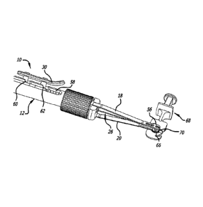
100301 An embodiment of the present inventive apparatus is illustrated
in FIG. 1. FIG. 1 illustrates a side view of a lens inserter apparatus 10 in
accordance with an embodiment of the invention. The lens inserter apparatus
includes a handle 12, which has a distal end 14 and a proximal end 16,
7
CA 02789568 2012-08-10
WO 2011/100012
PCT/US2010/057707
The lens inserter 10 also includes a pair of leaves IS and 20, which extend
from the distal end 14 of the handle 12. Preferably, the leaves 18 and 20 have
a length in a range of 10 min to 30 mm and a width in a range of I rnm to 4
trim. The thickness of each of leaves 18 and 20 is approxirrIstaly in. the
range
of 50 microns 0200 microns for a combined thiekne$s in a range of 100
microns to 400 microns. The leaves can be formed fmrn stainless steel or any
other suitable non corrosive material.. Top leaf 18 extends from a top surface
22 of the handle 12, while bottom leaf 20 extends from s bottom surface of (he
handle 12, The top leaf 18 and bottom leaf 20 are biased together, such that
art
inner surface of the top leaf 18 is in contact with an inner surface of the
bottom leaf 20, and am preferably made from a flexible, resilient material.
Additionally, a plunger 26 extends through the haulle 12. The plunger 26 has
a distal end portion 28, whieh extends beyond the dLstai end 14 of the handle
12, The plunger oan be formed from titanium or stainless steel or Inv other
suitable non corrosive material. An actuator 30 is coupled to the ph_mger 26
by posts 32 and 34. The actuator 30 can be used to move the plunger 28 via
finger rest 36. The ions inserter, apparatus 10 also includes a
longitudinal.ax'ts
100311 Fla 2 illustrates a top view Dia lens inserter in accordance
with an embodiment of the invention. The leaves 18 and 20 have a generally
flat elongate surface 38 and a distal end 40, which has a generally circular,
Ions shaped portion 42, which allows ft'sr the lens td be inserted into the
eye to
sit on a top surface orthe bottom leaf 20, The generally eircular lens shaped
8
CA 02789568 2012-08-10
WO 2011/100012
PCT/US2010/057707
portion preferably hes a =diametcz:irie range 02 nun to. 4 nun. As illustrated
iitIIO. 2, the Outer all of the handle 12 also decs a slot 44 in which the
actuator 30 can move in order to provide movement to the plunger 26. The
finger reg 36 of the actuator 30:Can. also be textured to provide ffiction
between the aotnatOr and the operator's finger.
P032.1 FIG. 3 illustrates a sectional -Wpw taken along axis ."e of the
embodiment Shown in Ira 1, Tix,- enter Wall:46 of the handle 1.2 deflim a
hmen 48, which extends through the length of the: handie 12. The plunger 20
is posidoned: withlh. the Inn en 48 of the handle 12. The plunger 26 ineludes
a
body portion 50 having a longitudinal and radial mita and is coupled to the
setnator 30 via posts 32 and.34, The body 50 of the iflungex:26: is movably
disposed within the lumen 48 of:the handle and can he moved along both the
longitudinal and radial axis of the plunger 26.. The plunger 26 can also be
biased against a spring 52 diSposed about a distal end 54 of the phingvr 26
within:the Omen 48 of the handle 12. The plunger 26 also includes the diStal
segment 28, whit* extends beyond the distal end 54 of thephinger 26 andtho
distal:end 14 of the handle 12 The distal segment:28 of the plunger 26 IS
positioned between the leaves 18 and 20 of the lem :inwter 19. The distal
segtnont 28 of the plunger 26 preferably has a thickness in a range of 100
micrenS te 300 miotons, The plunger 26 can also include a ring 53 at the
proximal end 54 of thd:body Dbraon 50 of the planer 26. The ring 53
preferably Mil be farmed of a =Material, which slides easily within the harnen
48 of the handle 12..
N033] MG. 4 illustrates a perspcotivo view or a distal eild Of the lebs:
insoit6t= a0Eariatts 10 in accordance with an embodiment of the invention, and
9
CA 02789568 2012-08-10
WO 2011/100012
PCT/US2010/057707
PIO. 5 illustrates a top view of the distal end of the lens inserter apparatus
10
shown in FIG, 4, FI08. 4 and 5 show the distal. end 40 of the leaves 18 and
20. The distal end 40 of each of the leaves 18 and 20 inchides a generally
flat
lens shaped portion 42. The lens shaped portion 42 is confõgured to allow a
ions de.signed he inserted into a flap or pocket in the cornea of the eye to
sit on
top of the surface of the distalend 40 of the bottom leaf 20. The distal end
40
of the leaves 18 and 20 also inchtdes=a slot 56. The slot 56 can be configured
to enable loading the lens onto the inserter 10. Additionally, the inner
surfaces
of the distal end 40 of the. leaves 18 and 20 sit on top of one mother in
order to
grip the lens for insertion into the pocket or flap in the cornea.
[0034] Fla 6 illustrates the handle 12 of the icav inserter 10 in further
detail, The handle 12 includes an. outer wall 46 that defines an opening 58.
The actuator 30, not shown, can extend through .the opening 58 and move
Within the opening 58. The opening ean be shaped such that the actuator 30
can be moved along the longitudinal axis of the plunger 26 or the radial Pas
Of
the plunger 26. The opening 58 includes notches 60 aud 62 such that the
=actuator 30 en. be moved along the radial axis of the plunger 26,
10035] FIG. 7 illustrates a top view of a plunger 26 fa lens inserter 10
in accordance with an embodiment of tho invention, and FIG. 8 illustrates a
side view of a plunger 26 of a ions inserter 10 in accordance with an
embodiment otthe invention. FIGS. 7 and 8 illustrate t1.11 distal segment 28O
the plunger 26, The distal segment 28 is generally flat and includes a fork 64
at the digtal end .66 of the distal segment 28 configured to push the lens off
of
the lens shaped portion 42 of the leaves I8 and 20.
f00361 FIGS, 9-1.1 illustrate a method of inserting a lens into a
pooket. ot flap i cornea in accordance=with an_ embodiment of the invention.
18
CA 02789568 2012-08-10
WO 2011/100012
PCT/US2010/057707
PIG. 9 illustrates the lens inserter 10 and a lens 66 for placement in the
pocket
or flap in the cornea. However, it is important to note that the lens inserter
10
can be used with any lens and packaging for the lens. Preferably, the lens 66
is approximately 2.5mm to 3,5 mm in diameter and has an edge thickness of
less than 20 microns, Although any lens suitable for insertion into a pocket
or
flap in a cornea can be used. As shown in PIGS. 9-11, the lens 66 is disposed
in packaging 68. Packaging 68 includes a post 70. As shown in FIG. 10, the
actuator 30 can be rotated about the radial axis of the plunger 26 into
notches
60 and 62 of the handle I2 in order to open the leaves 18 and 20. As the
plunger 26 is rotated it spreads the leaves 18 and 20 enough to place the
bottom leaf 20 under the lens 66. The slot 56 at the distal end 40 of the
leaves
18 and 20 can slide around the post 70 of the packaging to enable grasping of
the lens 66. When the lens 66 is positioned on the lens shaped portion 42 of
the bottom leaf 20, the actuator 30 can be rotated back out of the notches 60
and 62 in order to close the leaves and grasp the lens.
[00371 FIG. 12 illustrates a method of inserting a lens into a pocket or
flap in a cornea in accordance with an embodiment of the invention. Step 100
Shows the distal end 40 of the leaves 18 and 20 grasping the lens 66, and a
pocket 72 in the cornea 74 of the eye 76. Step 110 shows the lens inserter 10
inserted into the pocket 72. Step 120 shows the plunger 26 being advanced to
push the lens 66 off of the leaves 18 and 20. Additionally, step .130 shows
the
lens 66 placed in the eye 76 and the lens inserter 10 being removed from the
or 76.
[00381 The many features and advantages of the invention are
apparent from the detailed specification, and thus, it is intended by the
appended Glairns to cover all such. features and advantages of the invention,
CA 02789568 2012-08-10
WO 2011/100012
PCT/US2010/057707
which fall within the true spirit, and scope of the invention. Further, since
numerous modifications and variations will readily occur to those skilled in
the art, it is not desired to=limit the invention to the exact construction
and
operation ilthstrated and &scribed, and accordingly, all suitable
roodiEcations
and equivalents may be resorted to, falling within the scope of the invention.
:12