Note: Descriptions are shown in the official language in which they were submitted.
CA 02789668 2012-08-10
1
DESCRIPTION
TITLE OF THE INVENTION
BATTERY CONTROL SYSTEM
TECHNICAL FIELD
[0001] The present invention relates to a battery control system provided with
a
lithium-ion secondary battery having a positive electrode plate and a negative
electrode plate,
and a control device for controlling charge of the lithium-ion secondary
battery from a
power supply.
BACKGROUND ART
[0002] In recent years, chargeable and dischargeable lithium-ion secondary
batteries
(hereinafter, simply referred to as secondary batteries) are used for drive
power source of
vehicles, such as hybrid cars and electric cars. When such secondary batteries
are quickly
charged or regenerative current is used for charge in vehicles mounted with
secondary
batteries, such as hybrid cars and electric cars, a large charging current of
5C or IOC, for
example, is occasionally applied.
[0003] In a case where internal resistance of a secondary battery becomes high
due to
aging in the secondary battery, even if the same level of the charging
currents are applied to
the secondary battery, an inter-terminal voltage becomes higher than that at
an initial stage
(before deterioration, before the increase in the internal resistance) due to
the increase in the
internal resistance of the secondary battery. On the contrary, in a case where
a maximum
inter-terminal voltage of the secondary battery is set to a constant value to
charge the battery,
the larger the value of the internal resistance of the secondary battery is,
the higher the
inter-terminal voltage becomes. The inter-terminal voltage reaches the maximum
value
more quickly, and thus the charging cannot be further carried out. For this
reason, in the
CA 02789668 2012-08-10
2
secondary battery whose internal resistance increases, an electric quantity
(charge quantity)
by which the secondary battery can be charged is reduced more than a time
point where the
internal resistance is low.
[0004] On the contrary, Patent Document I discloses a method for charging a
lithium-ion
secondary battery comprising a step of detecting an internal resistance on
charging a
lithium-ion secondary battery, and a step of finally charging the secondary
battery by
performing constant-current charge with a final charging current and
performing
constant-voltage charge with a final charging voltage. In this technique, the
final charging
voltage at the final charging step is set to a value obtained by adding a
product of the
internal resistance and the final charging current of the secondary battery to
the set voltage
of the secondary battery. For this reason, this method enables a secondary
battery to be
charged up to the set voltage regardless of the level of the internal
resistance. Therefore,
according to this technique of Patent Document 1, a secondary battery that is
deteriorated
and has increased internal resistance can also be sufficiently charged.
RELATED ART DOCUMENTS
PATENT DOCUMENTS
[0005] Patent Document 1: JP2002-142379A
DISCLOSURE OF THE INVENTION
PROBLEMS TO BE SOLVED BY THE INVENTION
[0006] However, Patent Document 1 discloses the method for charging a
secondary
battery using the constant-voltage charge in which a charging current is
gradually lower near
full charge, and thus cannot be applied to a case, such as the quick charge or
the charge with
regenerative current, where a secondary battery is charged by a high electric
current.
[0007] Further, the internal resistance of a secondary battery includes DC
resistance of a
secondary battery (resistance due to an electrolytic solution in a separator,
resistance to
CA 02789668 2012-08-10
3
conduction of a current collector or the like), diffusion resistance of ion in
a positive
electrode plate, diffusion resistance of ion in a negative electrode plate,
reaction resistance of
the positive electrode plate, and reaction resistance of the negative
electrode plate. For this
reason, at the time of charging, polarization occurs in the negative electrode
plate due to the
reaction resistance of the negative electrode plate itself The larger a
product of the
reaction resistance of the negative electrode plate and the charging current
is, the larger this
polarization becomes. Therefore, when large polarization is occurred in the
negative
electrode plate by application of a high electric current at the time of
charging, an electric
potential of the negative electrode plate becomes lower than that of metallic
lithium, and the
metallic lithium might be deposited on the negative electrode plate.
[0008] Further, in some of negative electrode plates using a negative active
material such
as graphite, normal reaction resistance occurred in a negative electrode plate
within a normal
temperature range (20 to 45 C) is sufficiently lower than DC resistance, but
low-temperature reaction resistance in a low temperature range (-30 to 0 C)
becomes high,
and higher than the DC resistance.
[0009] Therefore, when secondary batteries using the negative electrode plates
having
such characteristics are charged in the low-temperature range, in order to
increase a quantity
of electricity for charge, it is considered that the internal resistance in
the low-temperature
range is used like Patent Document 1 and a product of this and an allowable
charging
current (for example, 5 C and 10 C) is added to a set voltage so that charge
is performed
with the added value as a maximum inter-terminal voltage. However, large
polarization is
occurred in the negative electrode plate because the reaction resistance of
the negative
electrode plate is high in the low-temperature range. Thus, metallic lithium
might be easily
deposited. For this reason, it is particularly difficult to change the maximum
inter-terminal
voltage into a high value and increase an amount of charge.
[0010] The present invention is devised in view of the above problem, and
provides a
battery control system capable of suitably charging a secondary battery using
a negative
CA 02789668 2012-08-10
4
electrode plate that has a characteristic such that reaction resistance
increases in a
low-temperature range, the system charging the battery up to a higher inter-
terminal voltage
while deposition of metallic lithium on the negative electrode plate of the
secondary battery
is being suppressed even when a battery temperature is in the low-temperature
range and the
charge is performed by a high electric current such as a case of quick charge
and charge by
regenerative current in vehicles.
MEANS OF SOLVING THE PROBLEMS
[0011] One aspect of the present invention provides a battery control system
including a
lithium-ion secondary battery (hereinafter, simply a secondary battery) having
a positive
electrode plate and a negative electrode plate, and a control device for
setting an allowable
maximum inter-terminal voltage and an allowable charging current at the time
of charging
of the secondary battery and controlling the charging from a power supply to
the secondary
battery, wherein when a normal temperature range ATE of a battery temperature
T is set to 20
to 45 C and a low-temperature range AT, of a battery temperature T is set to -
30 to 0 C, the
negative electrode plate has a characteristic such that when characteristics
of the negative
electrode plate are compared in cases where the battery temperature T is
within the normal
temperature range ATE and within the low-temperature range AT,, reaction
resistance Rr(T)
caused in the negative electrode plate is higher in the low-temperature range
AT,, and a ratio
of the reaction resistance Rr(T) of the negative electrode plate in internal
resistance R(T) of
the secondary battery is larger in the low-temperature range AT,, wherein the
battery control
system includes: a voltage storage unit for storing an initial maximum inter-
terminal voltage
V,,,o(T) allowed at an early use of the secondary battery in the maximum inter-
terminal
voltage V,,,(T) for each battery temperature T; a resistance storage unit for
storing initial
internal resistance Ro(T) caused at the early use of the secondary battery at
least at a
predetermined battery temperature Tea within the normal temperature range ATE;
an electric
current storage unit for storing the allowable charging current I,,,(T) for
each battery
CA 02789668 2012-08-10
temperature T; a difference obtaining unit for obtaining difference resistance
AR(Tja) as a
difference between normal internal resistance Rj(Tja) at temperature Tj within
the normal
temperature range Atj in the internal resistance of the secondary battery at
timing when the
battery temperature T of the secondary battery becomes the predetermined
battery
5 temperature Tja and the corresponding initial internal resistance Ro(Tja) at
the predetermined
battery temperature Tja stored in the resistance storage unit; and a maximum
voltage
calculating unit for, at least when the battery temperature T is within the
low-temperature
range AT,, setting the maximum inter-terminal voltage Vm(T) corresponding to
the battery
temperature T to a value obtained by adding a product of the difference
resistance AR(Tja)
and the allowable charging current I,,,(T) stored in the electric current
storage unit to the
initial maximum inter-terminal voltage Vmo(T) stored in the voltage storage
unit.
[0012] The battery control system includes the difference obtaining unit for
obtaining the
difference resistance AR(Tja) between the initial internal resistance R0(Tja)
and the normal
internal resistance Rj(Tja) of the secondary battery obtained at timing when
the
predetermined battery temperature Tja within the normal temperature range ATj
is reached.
Further, the maximum voltage calculating unit gives the maximum inter-terminal
voltage
Vr(T) at least within the low-temperature range AT, as the value obtained by
adding the
product of the difference resistance AR(Tja) and the allowable charging
current Im(T) to the
initial maximum inter-terminal voltage Vmo(T).
[0013] Therefore, the battery control system can further suppress a reduction
in a
charging amount of the secondary battery caused by an increase in the internal
resistance
due to deterioration and the like when the battery temperature T is at least
within the
low-temperature range AT,, in comparison with a case where the charge of the
secondary
battery is controlled with the maximum inter-terminal voltage Vm(T) being
maintained at the
initial maximum inter-terminal voltage Vmo(T) as a constant value.
[0014] Further, like Patent Document 1, not the product of the internal
resistance and an
electric current but a product of the difference resistance AR(T) as an
increase in the internal
CA 02789668 2012-08-10
6
resistance and the allowable charging current I,,,(T) is obtained. Since this
product is added
to the initial maximum inter-terminal voltage V,,,o(T), a suitable maximum
inter-terminal
voltage V,,,(T) corresponding to the increase in the internal resistance can
be obtained.
[0015] Further, although the battery temperature T is within the low-
temperature range
AT,, a value of the difference resistance AR(Tja) at the predetermined battery
temperature Tja
within the normal temperature range ATj is used as the difference resistance
AR(T). The
reason for this is as follows.
[0016] In this battery control system, the secondary battery includes the
negative
electrode plate having the above-described characteristics, namely, the
characteristics that a
ratio of the reaction resistance Rr(T) occurred in the negative electrode
plate at the battery
temperature T and the reaction resistance Rr(T) of the secondary battery in
the internal
resistance R(T) is larger in the low-temperature range AT, than in the normal
temperature
range ATJ.
[0017] When the internal resistance R(T) of the secondary battery increases
due to aging
variation or the like, the internal resistance R(T) generally increases by the
same ratio even
in any temperature range. Further, also respective resistance components in
the internal
resistance R(T) such as the reaction resistance and DC resistance generally
increase by the
same ratio (for example, similarly increases by 30%). Therefore, when absolute
values are
compared, the chronologic increase in low-temperature reaction resistance
Rr,(T,) at
temperature T, within the low-temperature range AT, is larger than an increase
in normal
reaction resistance R,j(Tj) at temperature Tj within the normal temperature
range AT. That
is to say, as to the difference resistance AR(T) representing the increase in
the internal
resistance R(T), the difference resistance AR(TI) at the temperature T, within
the
low-temperature range AT, obtains a value larger than the difference
resistance OR(Tj) at the
temperature Tj within the normal temperature range AT1.
[0018] If the battery temperature T is temperature T, within the low-
temperature range
AT,, differently from the battery control system, and the maximum voltage
calculating unit
CA 02789668 2012-08-10
7
adds a product of the difference resistance AR(TI) at the temperature T,
within the
low-temperature range AT, and the allowable charging current I,n(T,) to the
initial maximum
inter-terminal voltage V,no(T,), the difference resistance AR(TI) at the
temperature T, is large
as an absolute value as described above. For this reason, the maximum inter-
terminal
voltage V,n(T,) might obtain a too large value. As a result, the polarization
on the negative
electrode plate becomes too large, and thus the deposition of metallic lithium
might occur.
When the battery temperature T is within the low-temperature range AT, (T =
Ti) in such a
manner, it is occasionally not preferable that the difference resistance
AR(Ti) at the
temperature T, within the low-temperature range AT, is directly adopted, and
the maximum
inter-terminal voltage V,n(T,) is increased.
[0019] Therefore, according to the battery control system, when the battery
temperature
T is the temperature T, within the low-temperature range AT, in the maximum
voltage
calculating unit, instead of the difference resistance AR(Ti) corresponding to
the battery
temperature T (the temperature T, within the low-temperature range AT,), the
difference
resistance AR(Tja) at the predetermined battery temperature Tja within the
normal
temperature range ATE which is a comparatively smaller value is used, and a
product of this
difference resistance AR(Tja) and the allowable charging current I,n(Tj) is
added to the initial
maximum inter-terminal voltage V,no(Tj) to obtain the maximum inter-terminal
voltage
V,,,(Tj). For this reason, even in the case where the maximum inter-terminal
voltage V,.(Tj)
is set to a value larger than the initial maximum inter-terminal voltage
V,no(Tj), and even
when the internal resistance of the secondary battery increases due to aging
variation, the
reduction in the charging amount of the secondary battery can be suppressed,
whereas the
maximum inter-terminal voltage Vm(Tj) does not become too large. As a result,
the
deposition of metallic lithium on the negative electrode plate might not
occur.
[0020] In the secondary battery of the above battery control system using the
negative
electrode plate having a characteristic such that the reaction resistance
Rr(T)
(low-temperature reaction resistance Rr,(T,)) in the low-temperature range AT,
is increased
CA 02789668 2012-08-10
8
more than a case of the normal temperature range ATE, even when the internal
resistance
increases with age and the battery temperature T is within the low-temperature
range AT,
and charge is carried out by a large electric current in such a case as quick
charge and charge
by regenerative current in vehicles etc., the deposition of metallic lithium
on the negative
electrode plate of the secondary battery is suppressed, and at the same time
the secondary
battery can be charged suitably to a higher inter-terminal voltage.
[0021] Examples of the power supply include a DC power supply apparatus, a
battery
charger, an engine and a motor capable of generating power in a case where the
secondary
battery is installed in a vehicle.
[0022] When characteristics of the negative electrode plate are compared
between cases
where the battery temperature T is within the normal temperature range ATE and
within the
low-temperature range AT,, the reaction resistance Rr(T) occurred in the
negative electrode
plate is larger in the low-temperature range AT,, and a ratio of the reaction
resistance Rr(T)
of the negative electrode plate in the internal resistance R(T) of the
secondary battery is
higher in the low-temperature range AT,. That is to say, as to the reaction
resistance Rr(T)
occurred in the negative electrode plate composing a part of the internal
resistance R(T) of
the secondary battery, low-temperature reaction resistance Rr,(T,) at the
temperature T,
within the low-temperature range AT, is higher than normal reaction resistance
R~(TT) at the
temperature T1 within the normal temperature range ATE. Further, in comparison
with a
ratio R,;(TT)/Rj(T;) of the normal reaction resistance R,;(T) in the normal
internal resistance
R1(TT) as the internal resistance of the secondary battery at the temperature
T, within the
normal temperature range AT,, a ratio Rr,(T,)/R,(T,) of low-temperature
reaction resistance
Rr,(Ti) in low-temperature internal resistance RI(TI) as the internal
resistance of the
secondary battery at the temperature T, within the low-temperature range AT,
is larger.
Examples of such a negative electrode plate include negative electrode plates
containing
natural graphite and artificial graphite as a negative active material.
CA 02789668 2012-08-10
9
[0023] Further, the resistance storage unit may store at least the initial
internal resistance
Ro(T) at the predetermined battery temperature Tja within the normal
temperature range AT.
Therefore, the entire normal temperature range ATj or the entire range
including the
low-temperature range AT, are stored for each battery temperature T therein.
[0024] Further, in the battery control system, preferably, the negative
electrode plate has
a characteristic such that, as to the reaction resistance Rr(T), the low-
temperature reaction
resistance Rr,(Ti) at the temperature T, within the low-temperature range AT,
obtains a value
that is 7 or more times as large as the normal reaction resistance R,j(Tj) at
the temperature Tj
within the normal temperature range ATj, a ratio R,j(Tj)/Rj(Ti) of the normal
reaction
resistance Rd(T) in the normal internal resistance RAT) that is the internal
resistance R(T) at
the temperature Tj is 10% or less, and a ratio Rri(T,)/Ri(T,) of the low-
temperature reaction
resistance Rr,(T,) in the low-temperature internal resistance RI(TI) that is
the internal
resistance R(T) at the temperature T, is 20% or more.
[0025] In the above battery control system, since the negative electrode plate
has the
above characteristic, the low-temperature reaction resistance Rri(T,) is
securely larger than
the normal reaction resistance R,j(Tj), and the ratio Rd(Tj)/Rj(Tj) is
securely larger than the
ratio Rri(T,)/Ri(T,). For this reason, since the charge of the secondary
battery using such a
negative electrode plate is controlled, the maximum voltage calculating unit
uses the
difference resistance AR(Tja) at the predetermined battery temperature Tja
within the normal
temperature range AT; so as to be capable of obtaining the maximum inter-
terminal voltage
V,,,(T) from which a contribution of an increase in the reaction resistance
particularly in the
negative electrode plate is securely removed. Therefore, at least when the
battery
temperature T is within the low-temperature range AT,, a suitable maximum
inter-terminal
voltage V,,,(T) is obtained to charge the secondary battery.
[0026] Further, in any one of the above battery control systems, preferably,
the battery
temperature T is higher than the low-temperature range AT,, the maximum
voltage
CA 02789668 2012-08-10
calculating unit sets the initial maximum inter-terminal voltage V,,,o(T) to
be a value of the
maximum inter-terminal voltage Vm(T).
[0027] As described above, in the negative electrode plate of the secondary
battery to be
used in the battery control system, the ratio Rri(Ti)/Ri(Ti) of the low-
temperature reaction
5 resistance Rri(Ti) in the low-temperature internal resistance R1(Ti) is
larger in comparison
with the ratio R,j(Tj)/Rj(Tj) of the normal reaction resistance Rd(Tj) in the
normal internal
resistance Rj(T). For this reason, when the secondary battery is charged at
the battery
temperature T higher than the low-temperature range AT,, since a rise in the
internal
resistance of the secondary battery is smaller than the case where the battery
is charged at a
10 battery temperature Ti within the low-temperature range AT,, even if the
initial maximum
inter-terminal voltage Vmo(T) is used as the value of the maximum inter-
terminal voltage
V,,,(T), a reduction in the battery capacity due to the rise over time in the
internal resistance
is considered to be slight.
[0028] Therefore, in the battery control system, when the battery temperature
T is higher
than the low-temperature range AT,, the initial maximum inter-terminal voltage
V,,,o(T) is set
to be the value of the maximum inter-terminal voltage V,,,(T). As a result,
when the battery
temperature T is higher than the low-temperature range AT,, the maximum inter-
terminal
voltage V,,,(T) does not have to be changed, and thus the system can be more
simplified.
[0029] Further, any one of the above battery control systems may include a
resistance
obtaining unit for obtaining the normal internal resistance Rj(Tja) of the
secondary battery
when the battery temperature T of the secondary battery is the predetermined
battery
temperature Tja.
[0030] Since the battery control system has the resistance obtaining unit, the
battery
control system itself can obtain the normal internal resistance Rj(Tja) of the
secondary
battery and can autonomously change the maximum inter-terminal voltage Vm(T).
[0031] Further, the above battery control system may include a charging state
detecting
unit for detecting a charging state of the secondary battery; an open inter-
terminal voltage
CA 02789668 2012-08-10
11
storage unit for storing an open inter-terminal voltage at each charging state
of the secondary
battery in advance; and an open inter-terminal voltage obtaining unit for
obtaining the open
inter-terminal voltage based on the charging states detected by the charging
state detecting
unit, wherein the resistance obtaining unit is a means for, when the same
level of charging
currents are detected until a second time after a predetermined time passes
from a first time
just after an operation of the secondary battery is changed from discharging
to charging in a
charging period of the secondary battery, obtaining the normal internal
resistance Rj(Tja) by
using a difference between the open inter-terminal voltage corresponding to
the charging
state of the secondary battery at the first time and the inter-terminal
voltage of the secondary
battery at the second time, and a current value of the charging current, and
the
predetermined time is 1.0 second or less.
[0032] The battery control system has the charging state detecting unit, the
open
inter-terminal voltage storage unit and the open inter-terminal voltage
obtaining unit. In
the resistance obtaining unit, when the same level of the charging currents
are detected from
the first time to the second time, the normal internal resistance Rj(Tja) is
obtained by using a
difference between the open inter-terminal voltage of the secondary battery
and the
inter-terminal voltage of the secondary battery at the second time and the
current values of
the charging currents. That is to say, in the above battery control system,
the normal
internal resistance Rj(Tja) of the secondary battery can be obtained based on
a DC resistance
measuring (DC-IR) method.
[0033] When the internal resistance of the secondary battery is obtained based
on the
DC-IR method, if the time period taken for measuring the inter-terminal
voltage of the
secondary battery in a state that the charging current is applied
(hereinafter, a measuring
period) after the start of charging becomes long, the internal resistance to
be obtained
becomes high. Immediately after the charging current is started to be applied
to the
secondary battery, the reaction resistance of the positive electrode plate,
the reaction
resistance of the negative electrode plate and the DC resistance of the
secondary battery are
CA 02789668 2012-08-10
12
mainly occurred as the internal resistance, but thereafter diffusion
resistance of ions in the
positive electrode plate and the negative electrode plate gradually appear.
For this reason,
when the measuring period is long, besides the reaction resistance of the
positive electrode
plate, the reaction resistance of the negative electrode plate and the DC
resistance, a
component of the diffusion resistance is added to the internal resistance
obtained based on
the DC-IR method so that the internal resistance has a comparatively larger
value. As a
result, the difference resistance AR(T) obtains a value to which the increase
in the diffusion
resistance is added, and the maximum inter-terminal voltage of the secondary
battery
obtained by a maximum voltage obtaining unit also has a large value. For this
reason,
when the secondary battery is charged, the polarization of the negative
electrode plate
becomes too large, and thus metallic lithium might be deposited on the
negative electrode
plate.
[0034] On the contrary, according to the studies by the inventors, it is found
that when
the internal resistance of the secondary battery is measured by the DC-IR
method, if the
measuring period is set to 1.0 second or less, a ratio of the diffusion
resistance in the internal
resistance can be sufficiently low.
[0035] In the above battery control system, since the predetermined time from
the first
time to the second time corresponding to the measuring time is 1.0 second or
less, the
resistance obtaining unit can obtain the normal internal resistance Rj(Tja) in
which the ratio
of the diffusion resistance is sufficiently low. Therefore, when the charge is
carried out by
a large electric current, the deposition of metallic lithium on the negative
electrode plate of
the secondary battery is suppressed, and simultaneously the secondary battery
can be
charged suitably to a higher inter-terminal voltage.
[0036] The DC resistance measuring (DC-IR) method is a method for calculating
the
internal resistance of the secondary battery by using a change amount of the
inter-terminal
voltage of the secondary battery occurred when a constant charging current is
applied to the
secondary battery (concretely, the change amount between the open inter-
terminal voltage
CA 02789668 2012-08-10
13
immediately before the charging current is started to be applied and the inter-
terminal
voltage after the predetermined time passes from the start of the charge), and
the current
value of the charging current.
[0037] Further, it is preferable that the above battery control system has an
electric
current detecting unit for detecting the current value of the charging current
flowing in the
secondary battery at a predetermined cycle, and is configured so that when a
plurality of
current values detected by the electric current detecting unit for the period
from the first time
to the second time are equal to each other, the resistance obtaining unit
obtains the normal
internal resistance Rj(Tja).
[0038] In the above battery control system, since the current values of the
charging
currents obtained for the period from the first time to the second time are
equal to each other,
the normal internal resistance Rj(Tja) is obtained. For this reason, an error
due to a
fluctuation in the electric current is suppressed, and the more accurate
normal internal
resistance R;(Tja) of the secondary battery can be obtained.
[0039] Further, in the above battery control system, preferably, the
predetermined time in
the resistance obtaining unit is 0.1 seconds or less.
[0040] When the predetermined time is made to be shorter than 1.0 second, the
ratio of
the diffusion resistance in ions in the positive electrode plate and the
negative electrode plate
included in the obtained (calculated) normal internal resistance Rj(Tj) can be
further reduced.
In the battery control system, since the predetermined time from the first
time to the second
time is 0.1 seconds or less, when the charge is carried out by a large
electric current, the
deposition of metallic lithium on the negative electrode plate of the
secondary battery is
securely suppressed, and simultaneously the secondary battery can be suitably
charged to a
higher inter-terminal voltage.
[0041] Any one of the above battery control systems may include a normal
internal
resistance storage unit for storing the normal internal resistance Rj(Tja) of
the secondary
battery at the input time, which is externally input.
CA 02789668 2012-08-10
14
[0042] For example, when the battery control system is installed in a vehicle,
the normal
internal resistance Rj(Tja) of the secondary battery can be measured by using
the DC power
supply apparatus or the like installed outside the system (outside the
vehicle) at the time of
safety inspection or the like of the vehicle.
[0043] The battery control system has the normal internal resistance storage
unit.
Therefore, the normal internal resistance Rj(Tja) measured by the apparatus
outside the
system is stored in the normal internal resistance storage unit, and this can
be utilized. As a
result, even when the resistance obtaining unit is not provided into the
battery control system
(in the vehicle), the deposition of metallic lithium on the negative electrode
plate of the
secondary battery is securely suppressed by using the normal internal
resistance Rj(Tja), and
simultaneously the secondary battery can be charged suitably to a higher inter-
terminal
voltage.
[0044] An example of a method for obtaining the normal internal resistance of
the
secondary battery from the outside of the battery control system is a
measuring method
using an apparatus installed outside the battery control system, such as a DC
power supply
apparatus, a voltmeter and an ammeter. More concretely, examples of the method
for
obtaining the normal internal resistance using these external apparatuses
include the DC-IR
method and an AC impedance (AC-IR) method.
BRIEF DESCRIPTION OF THE DRAWINGS
[0045] FIG. 1 is a perspective view of a vehicle using a battery control
system of first
and second embodiments and first modified example;
FIG. 2 is a perspective view of a lithium ion secondary battery of first and
second
embodiments and first modified example;
FIG. 3 is an explanatory diagram of a HV control device of first and second
embodiments and first modified example;
FIG. 4 is a flowchart of first embodiment and first modified example;
CA 02789668 2012-08-10
FIG. 5 is a flowchart of first embodiment and first modified example;
FIG. 6 is a flowchart of first embodiment and first modified example;
FIG. 7 is a diagram to explain the first embodiment;
FIG. 8 is a graph to explain the first embodiment; and
5 FIG. 9 is a diagram to explain the second embodiment.
DESCRIPTION OF THE REFERENCE SIGNS
[0046]
Hybrid vehicle control device (Control device)
10 30 Front motor (Power supply)
40 Rear motor (Power supply)
50 Engine (Power supply)
101, 101A Lithium ion secondary battery
120 Positive electrode plate
15 130 Negative electrode plate
ATE Normal temperature range
AT] Low-temperature range
BS 1, BS2, BS3 Battery control system
Ic Charging current
20 IF Current value
I,,,(T) Allowable charging current
P 1 First time
P2 Second time
R(T) Internal resistance
Ro(T) Initial internal resistance
Rj(Tj) Normal internal resistance
R1(T1) Low-temperature internal resistance
CA 02789668 2012-08-10
16
Rr(T) Reaction resistance
R,1(Tj) Normal reaction resistance
Rri(Ti) Low-temperature reaction resistance
SC Charging state
T Battery temperature
Tja First battery temperature (Predetermined battery temperature)
Tj Temperature (within Normal temperature range)
T1 Temperature (within Low-temperature range)
TM I Predetermined time
Vm(T) Maximum inter-terminal voltage
V,,,o(T) Initial maximum inter-terminal voltage
VZ Open inter-terminal voltage
W I First ratio (Percentage Rd(Tj)/Rj(Tj))
W2 Second ratio (Percentage Rri(Ti)/Ri(Ti))
AR(T) Difference resistance
AV(T) Difference voltage (Difference between open inter-terminal voltage at
first time
and inter-terminal voltage at second time)
MODE FOR CARRYING OUT THE INVENTION
[0047] (First Embodiment)
A first embodiment of the present invention will be described below with
reference to drawings. First a vehicle I using a battery control system BS1
according to
the first embodiment will be described. FIG. 1 is a perspective view of the
vehicle 1.
[0048] The vehicle 1 has a plurality of (sixty, in the first embodiment)
lithium-ion
secondary batteries (hereinafter, simply referred to also as secondary
batteries) 101
composing a battery pack 80, a front motor 30, a rear motor 40, an engine 50
and a hybrid
vehicle control device (hereinafter, referred to also as an HV control device)
20 for
CA 02789668 2012-08-10
17
controlling charge of the secondary batteries 101 from the front motor 30, the
rear motor 40
and the engine 50. The vehicle 1 is a hybrid vehicle further having a cable
81, an inverter
82 and a vehicle body 89. The battery control system BSI in the vehicle 1
includes the
secondary batteries 101, the front motor 30, the rear motor 40, the engine 50
and the HV
control device 20.
[0049] The secondary batteries 101 composing the battery pack 80 are lithium-
ion
secondary batteries each having a positive electrode plate 120 and a negative
electrode plate
130. In each secondary battery 101, as shown in FIG. 2, an electrode body 110
and an
electrolytic solution (not shown) are housed in a battery case 180 having a
rectangular box
shape. The electrolytic solution is an organic electrolytic solution obtained
by adding
LiPF6 as a solute to a mixed organic solvent obtained by adjusting ethylene
carbonate, ethyl
methyl carbonate and dimethyl carbonate.
[0050] Further, the battery case 180 of the secondary battery 101 has a
battery case main
body 181 and a sealing lid 182 made of aluminum. A transparent insulating film
(not
shown) that is made of resin and is bent into a box shape is laid between the
battery case 180
and the electrode body 110.
[0051] The sealing lid 182 has a rectangular plate shape, and closes an
opening of the
main body 181 and is welded to the main body 181. A positive terminal portion
191 A and
a negative terminal portion 192A positioned on front ends of a positive
current collector 191
and a negative current collector 192 connected to the electrode body 110
penetrate the
sealing lid 182 to protrude from a lid surface 182a facing upward in FIG 2. An
insulating
member 195 made of insulating resin is laid between the positive terminal
portion 191 A or
the negative terminal portion 192A and the sealing lid 182 so as to insulate
them. Further,
a safety valve 197 having a rectangular plate shape is also sealed to the
sealing lid 182.
[0052] The electrode body 110 is configured so that the positive electrode
plate 120 and
the negative electrode plate 130 each having a band shape are wound into a
flattened shape
via a band-shaped separator (not shown) made of porous polyethylene. The
positive
CA 02789668 2012-08-10
18
electrode plate 120 and the negative electrode plate 130 of the electrode body
110 are
jointed to the positive current collector 191 or the negative current
collector 192 that have a
plate shape bent into a crank shape. The positive electrode plate 120 of the
electrode body
110 having a thin-plate band shape has positive current collecting foil (not
shown) that has a
band shape and is made of aluminum, and a positive active material layer (not
shown)
formed on both main surfaces of the positive current collecting foil.
[0053] On the other hand, the negative electrode plate 130 having a thin-plate
band
shape has negative current collecting foil (not shown) that has a band shape
and is made of
copper, and a negative active material layer (not shown) formed on both main
surfaces of
the negative current collecting foil. The negative active material layer
includes negative
active material particles made of natural graphite.
[0054] Internal resistance R(T) of the secondary battery 101 at a battery
temperature T
includes DC resistance Rd(T) of the secondary battery 101 (resistance
generated by
electrolytic solution in a separator or conducting resistance of the current
collectors 191 and
192), diffusion resistance Rs(T) of ions in the positive electrode plate 120,
diffusion
resistance Rn(T) of ions in the negative electrode plate 130, reaction
resistance Rp(T) of the
positive electrode plate 120, and reaction resistance Rr(T) of the negative
electrode plate 130.
Concretely, the internal resistance can be expressed by R(T) = Rd(T) + Rs(T) +
Rn(T) +
Rp(T) + Rr(T). The DC resistance Rd(T) of the secondary battery 101, the
diffusion
resistance Rs(T) in the positive electrode plate 120, the reaction resistance
Rn(T)in the
negative electrode plate 130, the reaction resistance Rp(T) of the positive
electrode plate 120
and the reaction resistance Rr(T) of the negative electrode plate 130 are
functions of the
battery temperature T. For this reason, the internal resistance R(T) is also a
function of the
battery temperature T, which is changed by the battery temperature T.
[0055] The negative electrode plate 130 using the negative active material
particles made
of natural graphite shows the following characteristics with regard to the
reaction resistance
Rr(T). That is to say, in the reaction resistance Rr(T) of the negative
electrode plate 130 in
CA 02789668 2012-08-10
19
the secondary battery 101, normal reaction resistance R,1(TT) at temperature
Tj where the
battery temperature T is within a normal temperature range ATE (concretely, a
range of 20 to
45 C) is sufficiently lower than DC resistance Rd(T,) of the secondary battery
101
(R,i(Tj) < Rd(Tj)). On the other hand, when the battery temperature T is
temperature T1
within a low-temperature range AT1 (concretely, -30 to 0 C), low-temperature
reaction
resistance Rrl(T1) becomes high, and is higher than the DC resistance Rd(T1)
of the
secondary battery (Rr1(Tl) > Rd(T1)).
[0056] The negative electrode plate 130 has a characteristic such that the
low-temperature reaction resistance R,1(T1) at temperature T1 in the low-
temperature range
AT1 is higher than the normal reaction resistance Rr,(Tj) at the temperature
Tj within the
normal temperature range ATE (Rrl(T1) > Rd(Tj)). Concretely, the low-
temperature reaction
resistance Rr1(T1) has a value that is 7 or more times larger than the normal
reaction
resistance R1(Tj).
[0057] Further, a first ratio W1 (= R~(Tj)/RR(Tj)) of the normal reaction
resistance Rd(Tj)
in the normal internal resistance Rj(T1) as the internal resistance of the
secondary battery 101
at the temperature Tj within the normal temperature range ATE is 10% or less.
A second
ratio W2 (= Rr1(T1)/R1(T1)) of the low-temperature reaction resistance Rr1(T1)
in the
low-temperature internal resistance R1(T1) as the internal resistance of the
secondary battery
at the temperature T1 within the low-temperature range AT1 is 20% or more.
When the
negative electrode plate 130 has the characteristic that the second ratio W2
is larger than the
first ratio W1, namely, when the temperature is low, the reaction resistance
becomes
particularly high, and the ratio of the reaction resistance in the internal
resistance of the
secondary battery 101 becomes also large.
[0058] When the secondary battery 101 is charged, polarization occurs in the
negative
electrode plate 130 by the reaction resistance Rr(T) of the negative electrode
plate 130.
Further, the larger a product of the reaction resistance Rr(T) of the negative
electrode plate
130 and a charging current is, the larger this polarization becomes.
Therefore, at the time
CA 02789668 2012-08-10
of charging, when a large electric current is applied to the secondary battery
101, large
polarization occurs in the negative electrode plate 130, and thus an electric
potential of the
negative electrode plate 130 is occasionally lower than an electric potential
of metallic
lithium. As a result, the metallic lithium is deposited on the negative
electrode plate 130.
5 That is to say, when the charging current to the secondary battery 101 is
constant, larger
polarization easily occurs and the metallic lithium is deposited more easily
in the negative
electrode plate 130 at the temperature T1 where the battery temperature T is
within the
low-temperature range AT, in comparison with the temperature Ti where the
battery
temperature T is within the normal temperature range ATE.
10 [0059] The HV control device 20 of the battery control system BS1 will be
described
below. The HV control device 20 includes a microcomputer 21 having a CPU, an
ROM
and an RAM, not shown, and being operated by a predetermined program. The HV
control
device 20 has a voltage sensor 25 for measuring an inter-terminal voltage V of
one
secondary battery IOTA of the secondary batteries 101 composing the battery
pack 80, a
15 current sensor 26 for measuring a level of a DC current flowing in the
secondary battery
101A (the battery pack 80), and a temperature sensor 27 for measuring the
battery
temperature T of the secondary battery lOlA (see FIG. 3). The voltage sensor
25 measures
a voltage between the positive terminal portion 191A and the negative terminal
portion
192A of the secondary battery 101A (see FIG. 3). The current sensor 26 is a
publicly
20 known DC current sensor. The temperature sensor 27 is arranged so that its
temperature
measuring portion touches the outside of the battery case 180 of the secondary
battery 101 A.
[0060] The HV control device 20 can detect states of the secondary batteries
101 (the
battery pack 80), the front motor 30, the rear motor 40, the engine 50 and the
inverter 82
directly or via the sensors, and makes various controls according to states of
the respective
portions. Therefore, control of the secondary batteries 101 (the battery pack
80) to be
conducted by the HV control device 20 in the battery control system BS 1 of
the first
embodiment will be described in detail below with reference to flowcharts in
FIGs. 4, 5 and
CA 02789668 2012-08-10
21
8. In the first embodiment, a main routine M1 shown in FIG. 4 is executed.
Steps S13,
S 14 and S 18 indicated by broken lines in the main routine M 1 are steps to
be used in a first
modified example, described later, and are not used in the first embodiment.
[0061] The ROM (not shown) of the microcomputer 21 stores an initial maximum
inter-terminal voltage V,,o(T) of the secondary battery 101A in a maximum
inter-terminal
voltage V,,,(T) for each battery temperature T, an allowable charging current
Im(T) of the
secondary battery 101A for each battery temperature T, and an open inter-
terminal voltage
VZ of the secondary battery 101 A for each state of charge SC of the secondary
battery 10 1 A
in advance. Further, the ROM also stores initial internal resistance Ro(Tja)
of the secondary
battery 101A at a predetermined first battery temperature Tja within the
normal temperature
range ATE in advance.
[0062] The main routine Ml shown in FIG. 4 will be described. When the
operation of
the vehicle 1 is started (key on) (YES at step Si), the sequence goes to step
S2, and the
battery temperature T of the secondary battery 101A, a current value IF
flowing in the
secondary battery 101A, and an inter-terminal voltage V(T) of the secondary
battery 101 A at
this time are respectively measured. In this main routine M1, the steps S2 to
S19 are
repeated for predetermined cycle time TC1 (at every 0.1 seconds, in the first
embodiment)
until the vehicle 1 is keyed off (see step S20, described later). For this
reason, in the first
embodiment, the battery temperature T, the current value IF, and the inter-
terminal voltage
V(T) are measured at every cycle time TC (0.1 seconds). Thereafter, the
sequence goes to
step S30 for a maximum voltage calculating subroutine.
[0063] The maximum voltage calculating subroutine S30 will be described with
reference to FIG. 5. The maximum inter-terminal voltage V,,,(T) set at the
maximum
voltage calculating subroutine S30 limits an upper limit of the inter-terminal
voltage V(T) of
the secondary battery 101 (10 1 A).
[0064] At the maximum voltage calculating subroutine S30, a determination is
made
whether the battery temperature T measured at step S2 is higher than the low-
temperature
CA 02789668 2012-08-10
22
range AT, or not, concretely, than a low-temperature range maximum temperature
Tiõ (0 C in
the first embodiment), which is a maximum temperature of the low-temperature
range AT1
(step S31).
[0065] When YES, that is, when the battery temperature T is higher than the
low-temperature range maximum temperature T1,,, the sequence goes to step S34.
On the
other hand, when NO, that is, when the battery temperature T is not higher
than the
low-temperature range maximum temperature Ti,,, the sequence goes to step S32.
[0066] When the secondary battery 101A (101) is charged by using the negative
electrode plate 130, if the battery temperature T is low, large polarization
may be occurred in
the negative electrode plate 130 relatively easily. Therefore, in the first
embodiment, when
the battery temperature T is higher than the low-temperature range maximum
temperature
T1,,, the initial maximum inter-terminal voltage V,,,o(T) stored in the ROM
(not shown) of the
microcomputer 21 is used as the maximum inter-terminal voltage V,,,(T), so
that the battery
control system BS1 is further simplified.
[0067] At step S32, by a resistance obtaining subroutine S40 described later,
it is
determined whether the normal internal resistance Rj(Tja) of the secondary
battery IOTA at
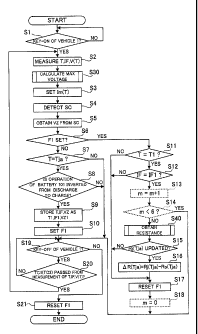
the predetermined first battery temperature Tja (20 C in the first
embodiment), described
later, in the normal temperature range ATE is already obtained or not.
[0068] When NO, namely, when the normal internal resistance Rj(Tja) is not yet
obtained
at the resistance obtaining subroutine S40, the sequence goes to step S34. On
the other
hand, when YES, namely, when the normal internal resistance Rj(Tja) is already
obtained,
the sequence goes to step S33, and the maximum inter-terminal voltage Vn,(T)
is set to a
value obtained by adding a product (AR(Tja) x Im(T)) of difference resistance
AR(Tja) and
the allowable charging current I,,,(T), described later, to the initial
maximum inter-terminal
voltage V,,,o(T). That is to say, the maximum inter-terminal voltage V,,,(T)
is set to Vm(T) =
Vro(T) + AR(Tja) X I,,(T). After this setting, the maximum voltage calculating
subroutine
S30 is terminated, and the sequence goes back to the main routine M1.
CA 02789668 2012-08-10
23
[0069] On the other hand, when the battery temperature T is higher than the
low-temperature range maximum temperature Tiõ at step S3 1, and when the
normal internal
resistance Rj(Tja) is not yet obtained at step S32 in the resistance obtaining
subroutine S40,
the maximum inter-terminal voltage V,,,(T) is set, at step S34, to the initial
maximum
inter-terminal voltage V,,,o(T) stored in the ROM of the microcomputer 21 in
advance.
After this setting, the maximum voltage calculating subroutine S30 is ended
and the
sequence goes back to the main routine M1.
[0070] At step S3 of the main routine Ml shown in FIG 4, the allowable
charging
current I,,,(T) relating to a charging current Ic to be applied to the
secondary batteries 101 is
set based on the battery temperature T measured at step S2. As a result, the
charging
current Ic that is larger than the allowable charging current I,,,(T) is
prevented from flowing
in the secondary batteries 101. As the allowable charging current I,,, (T),
concretely, one is
selected from the allowable charging currents I,,,(T) stored in the ROM for
each battery
temperature T in advance according to the battery temperatures T at each time
point.
[0071] The state of charge SC (a value of SOC) of the secondary battery 101A
at that
time is detected at step S4. Concretely, after the secondary battery 101 A of
which the state
of charge SC is known is mounted to the vehicle 1, the HV control device 20
separately
calculates the state of charge SC of the secondary battery 10 1 A based on
histories of a value
of a discharge current flowing in the secondary battery 101A and values of the
charging
current Ic. Therefore, this value is read at step S4.
[0072] Thereafter, at step S5, the open inter-terminal voltage VZ of the
secondary battery
101A is obtained according to the detected state of charge SC. Concretely, one
is selected
from the open inter-terminal voltages VZ stored in the ROM for each state of
charge SC in
advance according to the detected state of charge SC of the secondary battery
101A, and this
is used as the open inter-terminal voltage VZ at that time.
[0073] Thereafter, a determination is made at step S6 whether an inversion
flag Fl,
described later, is set or not. When YES, namely, when the inversion flag F1
is set, the
CA 02789668 2012-08-10
24
sequence goes to step S 11. On the other hand, when NO, namely, when the
inversion flag
Fl is reset, the sequence goes to step S7.
[0074] At step S7, it is determined whether the battery temperature T obtained
(measured) at step S2 is the predetermined first battery temperature Tja (in
the first
embodiment, for example, 20 C) within the normal temperature range ATE (20 C
<_ T <
45 C). When NO, namely, when the battery temperature T is not the first
battery
temperature Tja, the steps from S8 to S l 0 are skipped and the sequence goes
to step S19.
On the other hand, when YES, namely, when the battery temperature T is the
first battery
temperature Tea, the sequence goes to step S8.
[0075] The first embodiment describes an example where when the battery
temperature
T is the predetermined first battery temperature Tja within the normal
temperature range ATE ,
a process such as step S8 is executed. However, for example, when the battery
temperature
T is within the normal temperature range ATE , and is also predetermined
temperatures (for
example, a second battery temperature (= 30 C) and a third battery temperature
(= 40 C))
other than the first battery temperature Tja, the process such as step S8 is
executed similarly.
At the resistance obtaining subroutine S40, described later, the normal
internal resistance at
any of the above temperatures is calculated, and this may be used.
[0076] At step S8, it is determined from the current value IF of the secondary
battery
101 A obtained (measured) at step S2 whether the operation of the secondary
battery 101 A is
changed (inverted) from discharging to charging or not. When NO, namely, when
the
operation of the secondary battery 101A is not inverted from discharging to
charging, the
sequence goes to step S19. On the other hand, when YES, namely, when the
operation of
the secondary battery 101 A is inverted from discharging to charging, the
sequence goes to
step S9.
[0077] At step S9, the battery temperature T, the current value IF and the
open
inter-terminal voltage VZ at the timing immediately after the operation of the
secondary
battery 101 A is inverted from discharging to charging (first time P 1)
obtained at step S2 are
CA 02789668 2012-08-10
stored as a first time battery temperature Ti, a first time current value IF 1
and a first time
open voltage VZI. The inversion flag Fl is set in the microcomputer 21 (step
S10), and
the sequence goes to step S 19.
[0078] On the other hand, when it is determined at step S6 that the inversion
flag Fl has
5 been set (YES), namely, in a case of timing (second time P2) of a next cycle
time TC 1 that is
0.1 seconds after the setting of the inversion flag F1, the sequence goes to
step S11 where it
is determined whether the battery temperature T at the second time P2 is equal
to the first
time battery temperature Ti stored at step S9 or not, that is, the battery
temperature Ti of
0.1 seconds before. When NO, i.e., when the battery temperature T at the
second time P2
10 is different from the first time battery temperature Ti, the sequence goes
to step S17. On
the other hand, when YES, i.e., when the battery temperature T at the second
time P2 is
equal to the first time battery temperature Ti, the sequence goes to step S12.
[0079] At step S12, it is determined whether the current value IF at the
second time P2
measured at step S2 is the same as a first time current value IF 1 at first
time P 1 stored at step
15 S 10 or not. When NO, i.e., when the current value IF at the second time P2
is different
from the first time current value IF 1, the sequence goes to step SIT On the
other hand,
when YES, i.e., when the current value IF at the second time P2 is equal to
the first time
current value IF 1 (see an explanatory diagram in FIG. 7), the sequence goes
to the resistance
obtaining subroutine at step S40.
20 [0080] The resistance obtaining subroutine S40 will be described with
reference to FIG.
6. The resistance obtaining subroutine S40 is a resistance obtaining unit for
obtaining the
normal internal resistance Rj(Tja) of the secondary batteries 101 at the time
when the battery
temperature T is the first battery temperature Tja (20 C) using a pseudo-DC
resistance
measuring (DC-IR) method. In the main routine Ml, as described above, the
battery
25 temperature T, the current value IF and the inter-terminal voltage V(T)
(accordingly, the
open inter-terminal voltage VZ) are measured and detected at step S2 in every
predetermined cycle time TCl (0.1 seconds). Therefore, at the resistance
obtaining
CA 02789668 2012-08-10
26
subroutine S40 in the first embodiment, when the current value IF measured at
the second
time P2 after a predetermined time TM1 (0.1 seconds) is equal to the first
time current value
IF1, the normal internal resistance Rj(Tja) of the secondary battery IOTA at
the first battery
temperature Tea is obtained based on a change (difference voltage AV(Tja),
described later) in
the inter-terminal voltage of the secondary battery 101A caused during this
time period and
the current value IF (the first time current value IF 1).
[0081] More concretely, at step S41, the first time open voltage VZ1 stored
0.1 seconds
before at step S9 is subtracted from the inter-terminal voltage V(Tia)(a
second time
inter-terminal voltage V(Tja)2) at the second time P2 so that a difference is
calculated, and
this difference is assumed as the difference voltage AV(Tja) at the first
battery temperature
Tea.
[0082] At step S42, the calculated difference voltage AV(Tja) and the stored
first time
current value IF 1 are stored as a pair in the RAM.
[0083] Next, "n" representing the number of stored pairs is incremented (step
S43). At
step S44, it is determined whether the number n is smaller than 64 or not.
When YES, that
is, when the number n is smaller than 64, the resistance obtaining subroutine
S40 is ended,
and the sequence goes back to the main routine M1. This is because the number
of pairs of
the difference voltages AV(Tja) and the first time current values IF1 is
insufficient to
calculate the normal internal resistance Rj(Tja) with small error.
[0084] On the other hand, when NO, namely, when the number n is 64, the normal
internal resistance Rj(Tja) at the first battery temperature Tea is calculated
based on 64 pairs
of the difference voltages AV(Tja) and the first time current values IF1 (step
S45).
Concretely, as shown in FIG. 8, coordinate points indicating the combinations
of the first
time current values IF1 and the difference voltages AV(Tja) are dotted on a
graph in which
the first time current value IF1 is plotted along a horizontal axis and the
difference voltage
4V(Tia) is plotted along a vertical axis. A proximate line of a plurality of
coordinate points
is obtained by using a least squares method. A tilt of the proximate line is
the new normal
CA 02789668 2012-08-10
27
internal resistance Rj(Tja) of the secondary batteries 101 at the initial
battery temperature Tja.
In such a manner, the new normal internal resistance Rj(Tja) at the initial
battery temperature
Tea is obtained.
[0085] At step S46, the number n is set to 0 (zero), the resistance obtaining
subroutine
S40 is ended, and the sequence goes back to the main routine M1 and goes to
step 515.
[0086] In step S15 of the main routine M1, it is determined whether the normal
internal
resistance Rj(Tja) of the secondary battery 101 A at the first battery
temperature Tja is newly
obtained (updated) or not at the resistance obtaining subroutine S40. When NO,
namely,
when the normal internal resistance Rj(Tja) is not updated at the resistance
obtaining
subroutine S40, step S16 is skipped, and the sequence goes to step SIT On the
other hand,
when YES, namely, when the normal internal resistance Rj(Tja) is updated, the
sequence
goes to step S16.
[0087] At step S16, the difference resistance AR(Tja) of the secondary battery
101A
when the battery temperature T is the first battery temperature Tja is
obtained. The
difference resistance AR(Tja) is concretely a difference (AR(Tja)) = Rj(Tja) -
Ro(Tja)) that is
obtained by subtracting the initial internal resistance Ro(Tja) at the first
battery temperature
T;a from the normal internal resistance Rj(Tja) at the first battery
temperature Tja obtained at
the resistance obtaining subroutine S40. As the initial internal resistance
Ro(Tja), a value
(Ro(Tia)) of the initial internal resistance Ro(T) stored in the ROM in
advance corresponding
to the first battery temperature Tea is used.
[0088] In such a manner, the difference resistance AR(Tja) is obtained, so
that YES is
selected at step S32 in the maximum voltage calculating subroutine S30
thereafter, and the
sequence goes to step S33. That is to say, the maximum inter-terminal voltage
V,,,(T) of
the secondary batteries 101 in the low-temperature range AT, can be set by
using the
difference resistance AR(Tja), the initial maximum inter-terminal voltage
V,,,o(T) and the
allowable charging current I,,,(T).
CA 02789668 2012-08-10
28
[0089] The inversion flag F 1 is reset at step S 17 and the sequence goes to
step S 19. At
step S 19, it is determined whether the vehicle 1 is keyed off or not. When NO
at this step,
the sequence goes to step S20. When YES, to the contrary, the sequence goes to
step S21.
[0090] At step S20, it is determined whether or not the predetermined cycle
time TC 1
(0.1 seconds) passes since the measurement of the battery temperature T, the
current value
IF and the inter-terminal voltage V(T) of the secondary battery 101A at step
S2. When NO,
namely, when the predetermined cycle TC1 does not pass since the last
measurement, the
sequence goes back to step S19, and the steps S19 and S20 are repeated
(namely, to wait
until the cycle time TC 1 passes). On the other hand, when YES, namely, when
the cycle
time TC1 passes since the measurement at step S2, the sequence goes back to
step S2, and
the steps S2 to S20 are repeated. On the other hand, the inversion flag F1 is
reset at step
S21 and the main routine M1 is ended regardless of whether the inversion flag
Fl is set or
not.
[0091] In the first embodiment, the HV control device 20 corresponds to a
control device,
the front motor 30, the rear motor 40 and the engine 50 correspond to power
supplies, the
allowable charging current I,,,(T) corresponds to the allowable charging
current. The
microcomputer 21 of the HV control device 20 that stores the initial maximum
inter-terminal voltages Vmo(T) of the secondary battery 101 A for each battery
temperature T,
the initial internal resistances Ro(Tia) of the secondary battery IOTA at the
first battery
temperature Tja within the normal temperature range AT,, the allowable
charging currents
I,,,(T) of the secondary battery 101A for each battery temperature T, and the
open
inter-terminal voltages VZ of the secondary battery 101 A for each state of
charge SC of the
secondary battery 101A corresponds to a voltage storage unit, a resistance
storage unit, a
current storage unit and an open inter-terminal voltage storage unit,
respectively. Further,
the resistance obtaining subroutine S40 corresponds to a resistance obtaining
unit, step S 16
in the main routine M1 corresponds to a difference obtaining unit, the maximum
voltage
calculating subroutine S30 corresponds to a maximum voltage calculating unit,
step S5
CA 02789668 2012-08-10
29
corresponds to a charging state detecting unit, and step S6 corresponds to an
open
inter-terminal voltage obtaining unit, respectively.
[0092] The battery control system BS1 according to the first embodiment
includes step
16 of obtaining the difference resistance AR(Tja) of the secondary battery 101
A between the
normal internal resistance Rj(Tja) obtained at the timing of the first battery
temperature Tja
(for example, 20 C) within the normal temperature range ATE and the initial
internal
resistance Ro(Tja). Further, when the battery temperature T is within the low-
temperature
range AT,, at the maximum voltage calculating subroutine S30, the maximum
inter-terminal
voltage V,,,(T) is set to a value obtained by adding a product of the
difference resistance
AR(Tja) and the allowable charging current Im(T) to the initial maximum inter-
terminal
voltage V,,,o(T).
[0093] Therefore, in the battery control system BS1, when the battery
temperature T is
within the low-temperate range AT,, a reduction in the charging amount of the
secondary
battery 10 1 A that is caused by an increase in the internal resistance due to
deterioration can
be suppressed more in comparison with a case where the charge of the secondary
batteries is
controlled by using the maximum inter-terminal voltage V,,,(T) as a constant
value of the
initial maximum inter-terminal voltage V,,,o(T).
[0094] Further, like Patent Document 1, not a product of the internal
resistance and the
electric current but a product of the difference resistance AR(Tja) and the
allowable charging
current In(T) equivalent to an increase in the internal resistance is
obtained, and this product
is added to the initial maximum inter-terminal voltage V,,, (T). For this
reason, the
maximum inter-terminal voltage V,,,(T) suitable for the increase in the
internal resistance can
be obtained.
[0095] Further, in the battery control system BS1, when the battery
temperature T is
within the low-temperature range AT,, at the maximum voltage calculating
subroutine S30,
not the difference resistance AR(Ti) corresponding to the battery temperature
T (a
temperature T1 in the low-temperature range AT,) but the difference resistance
AR(Tja) at the
CA 02789668 2012-08-10
first battery temperature Tea in the normal temperature range AT3 to be a
comparatively
smaller value than the difference resistance AR(T1) is used. A product of the
difference
resistance AR(Tja) and the allowable charging current I,,,(T) is added to the
initial maximum
inter-terminal voltage V,,,o(T), so that the maximum inter-terminal voltage
V,,,(T) is obtained.
5 For this reason, when the maximum inter-terminal voltage V,,,(T) is set to a
value larger than
the initial maximum inter-terminal voltage V,,,o(T), even if the internal
resistance of the
secondary batteries increases due to aging variation, the reduction in the
charging amount of
the secondary battery 101A can be suppressed. On the other hand, the maximum
inter-terminal voltage V,,,(T) does not obtain a too large value, and
deposition of metallic
10 lithium on the negative electrode plate 130 due to polarization does not
occur.
[0096] In the battery control system BS1, the secondary battery 101 (101A)
uses the
negative electrode plate 130 having a characteristic such that the low-
temperature reaction
resistance Rrl(Ti) at the temperature T1 within the low-temperature range AT,
increases more
than a case of the normal temperature range AT3. Even when the internal
resistance of the
15 secondary battery 101 increases with age, the battery temperature T is
within the
low-temperature range AT,, and the charge is carried out by a large electric
current like quick
charge or charge with regenerative current in a vehicle, the deposition of
metallic lithium on
the negative electrode plate 130 of the secondary battery 101A is suppressed,
and
simultaneously the secondary battery 101 (101A) can be charged suitably up to
a higher
20 inter-terminal voltage.
[0097] Further, the secondary battery IOTA uses the negative electrode plate
130 having
the above characteristic, namely, a characteristic such that the low-
temperature reaction
resistance Rri(Ti) has a value that is 7 or more times larger than the normal
reaction
resistance R~(TT), and the first ratio W l (= Rj(Tj)/Rj(Ti)) is 10% or less
and the second ratio
25 W2 (= Rri(Tl)/Ri(Ti)) is 20% or more.
[0098] In the battery control system BS1, since the charge of the secondary
battery 101
(101A) using such a negative electrode plate 130 is controlled, particularly
the maximum
CA 02789668 2012-08-10
31
inter-terminal voltage V,,,(T) from which contribution of an increase in the
reaction
resistance in the negative electrode plate 130 is securely excluded can be
obtained. For this
reason, when the battery temperature T is within the low-temperature range
AT,, the suitable
maximum inter-terminal voltage V,,,(T) is obtained so that the secondary
battery 101 (101 A)
can be charged.
[0099] Further, in the negative electrode plate 130 of the secondary battery
101 used in
the battery control system BS1, as described above, the second ratio W2 (=
Rr,(T,)/R,(T,)) is
larger than the first ratio W1 (= Rd(T)/R;(T)). For this reason, when the
secondary
batteries 101 are charged at the battery temperature T higher than the low-
temperature range
AT,, a rise by the internal resistance of the secondary batteries 101 is
smaller than a case
where charge is carried out at the battery temperature T within the low-
temperature range
AT,. For this reason, it is considered that even when the initial maximum
inter-terminal
voltage V,,,o(T) is used as the maximum inter-terminal voltage V,,,(T), a
reduction in a
battery capacity due to the rise over time in the internal resistance is
small.
[0100] Therefore, in the battery control system BS1 according to the first
embodiment,
when the battery temperature T is higher than the low-temperature range AT,,
the initial
maximum inter-terminal voltage V,,,o(T) is set to a value of the maximum inter-
terminal
voltage V,,,(T). As a result, when the battery temperature T is higher than
the
low-temperature range AT,, the maximum inter-terminal voltage V,,,(T) does not
have to be
changed, so that the system can be further simplified.
[0101] Further, since the battery control system BS1 is provided with the
resistance
obtaining subroutine S30, the battery control system BS1 itself can obtain the
normal
internal resistance Rj(Tja) of the secondary battery 101 (101A), and can
autonomously
change the maximum inter-terminal voltage Vm(T).
[0102] When the battery control system BS1 detects the same current values IF
of the
charging currents Ic at the first time PI and the second time P2, the normal
internal
resistance Rj(Tja) is obtained by using the difference voltage AV(Tja) between
a first time
CA 02789668 2012-08-10
32
open inter-terminal voltage VZ 1 of the secondary battery l O l A at the first
time PI and a
second time inter-terminal voltage V(Tja)2 of the secondary battery 101A at
the second time
P2, and the current value IF (the first time current value IF 1) of the
charging current Ic.
That is to say, in the battery control system BS1, the normal internal
resistance Rj(Tja) of the
secondary battery 101 (101A) can be obtained according to a DC-IR method.
[0103] Prior to the obtaining of the normal internal resistance Rj(Tj) of the
secondary
batteries according to the DC-IR method, a relationship between the time from
the start of
charging to the measurement of a voltage (measuring period) and the normal
internal
resistance Rj(Tj) was verified.
[0104] Concretely, the secondary battery A, having a short time passed since
being
manufactured, is prepared by selecting from the secondary batteries 101
similar to the one in
the first embodiment, and the internal resistance (the normal internal
resistance) at 25 C (TT
= 25 C) where the battery temperature T was within the normal temperature
range AT, was
measured by the DC-IR method. At this time, in the DC-IR method, the time
(measuring
period) from the start of flowing the charging current Ic to the measurement
of the
inter-terminal voltage of the secondary battery A was changed into 0.1
seconds, 1.0 second,
10.0 seconds and 20.0 seconds so that the measurement was made. Table 1 shows
the
normal internal resistance of the secondary battery A (the secondary battery A
before an
accelerated deterioration test, described later) at the respective measuring
periods.
CA 02789668 2012-08-10
33
[0105]
[Table 1]
Normal internal resistance me
Measuring Before After Difference Calculated max.
period (sec.) accelerated accelerated resistance AR inter-terminal voltage
deterioration deterioration (MO) Vm(-5) (V)
test (Initial) test
0.1 5.0 5.8 0.8 4.126
1.0 5.2 6.5 1.3 4.211
10.0 6.0 8.0 2.0 4.260
20.0 7.0 9.6 2.6 4.302
[0106] According to Table 1, it is found that the longer the measuring period
becomes,
the higher the normal internal resistance of the secondary battery A becomes.
The reason
for this is as follows. Immediately after the charging current Ic starts to be
applied to the
secondary battery A, the reaction resistance Rp(TT) of the positive electrode
plate 120, the
reaction resistance Rr(Tj) of the negative electrode plate 130 and the DC
resistance Rd(Tj) of
the secondary battery A (the secondary battery 101) are mainly occurred, but
thereafter
gradually the diffusion resistance Rs(T) of ions in the positive electrode
plate 120 and the
diffusion resistance Rn(T) of ions in the negative electrode plate 130 are
also occurred.
For this reason, when the measuring period is long, besides the reaction
resistance Rp(Tj) of
the positive electrode plate 120, the reaction resistance Rr(Tj) of the
negative electrode plate
130 and the DC resistance Rd(T,), components of diffusion resistances Rs(T;)
and Rn(Tj) in
the electrodes 120 and 130 are added to the normal internal resistance
obtained by the
DC-IR method.
[0107] Thereafter, the accelerated deterioration test was conducted for the
secondary
battery A. Concretely, with use of a DC power supply apparatus (not shown),
the
secondary battery A was charged and discharged by a constant current of 4C,
repeatedly
1000 times in an alternative manner, under a temperature environment of 60 C
and within a
CA 02789668 2012-08-10
34
voltage range of 2.5 to 4.1 V. As to the secondary battery A that was subject
to the
accelerated deterioration test, the internal resistance (the normal internal
resistance) was
measured by using the DC-IR method at battery temperature T(T) of 25 C
similarly to the
condition before the accelerated deterioration test. Table I shows also
results of the
secondary battery A after the accelerated deterioration test.
[0108] According to Table 1, as the measuring period is longer, the normal
internal
resistance of the secondary battery A after the accelerated deterioration test
also becomes
higher similarly to the initial case. Therefore, it is found that this normal
internal resistance
of the secondary battery A has a tendency similar to that of the normal
internal resistance
before the accelerated deterioration test. Further, the difference resistance
AR before and
after the accelerated deterioration test (a difference obtained by subtracting
the normal
internal resistance before the accelerated deterioration test from the normal
internal
resistance after the accelerated deterioration test) is 0.8 mQ at the
measuring period of 0.1
seconds, 1.3 mu at 1.0 second, 2.0 mu at 10.0 seconds, and 2.6 ml) at 20.0
seconds. As a
result, it is found that as the measuring period is longer, the difference
resistance AR also
becomes larger.
[0109] The relationship between the maximum inter-terminal voltage and the
battery
capacity of the secondary batteries 101 was verified. Concretely, as the
secondary batteries
101, two secondary batteries (a secondary battery B and a secondary battery
C), having a
short time passed since being manufactured, were prepared.
[0110] Capacities of the secondary batteries B and C were measured.
Concretely,
discharged capacities at the time when the secondary batteries B and C of 4.1
V (full
charging voltage) were discharged up to 2.5 V by a constant (1 C) discharge
current under
the temperature environment of 25 C were measured.
[0111] A charge and discharge pulse cycle test was conducted on the secondary
batteries
B and C. In this charge and discharge pulse cycle test, the secondary
batteries B and C that
were brought into a charging state of SOC 60% under the temperature
environment of -5 C
CA 02789668 2012-08-10
were continuously charged by a constant current of 2 C for 1.0 second, a
constant current of
6 C for 1.0 second, and a constant current of 10 C for 1.0 seconds. With
downtime of 10.0
seconds, the secondary batteries B and C were continuously discharged by a
constant current
of 2 C for 1.0 second, a constant current of 6 C for 1.0 second, and a
constant current of 10
5 C for 1.0 second, and thereafter, took a downtime for 10.0 seconds. Such a
charge and
discharge pulse cycle test was repeated 10 times.
[0112] In the charge and discharge pulse cycle test, the maximum inter-
terminal voltage
V,,,(-5) at the battery temperature T of -5 C was set to different values
between the
secondary battery B and the secondary battery C. Concretely, the maximum inter-
terminal
10 voltage V,,,(-5) of the secondary battery B was set to 4.12 V, and the
maximum
inter-terminal voltage V,,,(-5) of the secondary battery C was set to 4.18 V
(see Table 2).
[0113] After the charge and discharge pulse cycle test, the capacities of the
secondary
batteries B and C were again measured. Concretely, similarly to the method
used before
the charge and discharge pulse cycle test, the discharge capacities at the
time when the
15 batteries were discharged up to 2.5 V by the constant (1 C) discharge
current under a
temperature environment of 25 C were measured. Capacity maintaining factors
(%) of the
secondary batteries B and C were respectively calculated before and after the
charge and
discharge pulse cycle test. Concretely, a quotient obtained by dividing the
discharge
capacities of the secondary batteries B and C after the charge and discharge
pulse cycle test
20 by the discharge capacities before the charge and discharge pulse cycle
test is expressed by
ratio.
Table 2 shows the capacity maintaining factors (%) of the secondary batteries
B and
C.
CA 02789668 2012-08-10
36
[0114]
[Table 2]
Max. inter-terminal Capacity
voltage Vm(-5) (V) maintaining factor
(%)
Secondary batteries Secondary battery B 4.12 99.4
before accelerated
deterioration test Secondary battery C 4.18 90.0
Secondary battery D 4.12 99.4
Secondary battery E 4.18 99.4
Secondary batteries
after accelerated Secondary battery F 4.21 99.2
deterioration test
Secondary battery G 4.26 98.6
Secondary battery H 4.30 80.0
[0115] According to Table 2, the capacity maintaining factor of the secondary
battery B
is 99.4% that is higher than 99%, whereas the capacity maintaining factor of
the secondary
battery C is 90.0% that is greatly lower than that of the secondary battery B.
[0116] In the secondary battery C whose maximum inter-terminal voltage V,,,(-
5) is 4.18
V higher than 4.12 V of the secondary battery B, large polarization is
occurred in the
negative electrode plate due to the charge by means of the high charging
current within the
low-temperature range AT, in the charge and discharge pulse cycle test. At
this time, the
electric potential of the negative electrode plate may occasionally be lower
than the electric
potential of the metallic lithium. For this reason, the metallic lithium is
deposited on the
negative electrode plate, and thus it is considered that the capacity of the
secondary battery
C is reduced after the charge and discharge pulse cycle test.
[0117] Therefore, in the secondary batteries 101 according to the first
embodiment, at an
initial stage where the internal resistance does not rise due to progress of
deterioration, the
maximum inter-terminal voltage is suitably set to 4.12 V. Therefore, this
value is used as
the initial maximum inter-terminal voltage V,,,o(-5) of the secondary
batteries 101
(secondary batteries A to H) at the battery temperature T of -5 C.
CA 02789668 2012-08-10
37
[0118] As described above, the internal resistance of the secondary battery A
at various
measuring periods were measured by the DC-IR method (see Table 1). A length of
the
measuring period, that is used for the calculation of the difference
resistance AR(Tja)
according to the formula (Vm(T) = Vm0(T) + AR(Tja) x Im(T)) to be used at the
maximum
voltage calculating subroutine S30, is studied. The allowable charging
currents Im(-5) of
the secondary batteries A to C at the battery temperature T of -5 C are 12 C
(= 70 A).
According to this, the maximum inter-terminal voltage V,,,(-5) of the
secondary battery A at
-5 C is calculated by using the difference resistance AR(Tja) of the secondary
battery A at
each time described in Table 1 and the formula (Vm(T) = Viii0(T) + AR(Tja) x
Im(T)) used at
the maximum voltage calculating subroutine S30.
[0119] The initial maximum inter-terminal voltage V,,0(-5) is 4.12 V as
described above.
As a result, the maximum inter-terminal voltage Vm(-5) is 4.176 V at the
measuring period
of 0.1 seconds, 4.211 Vat 1.0 second, 4.260 Vat 10.0 seconds, and 4.302 Vat
20.0 seconds
(see Table 1).
[0120] Relatively fresh secondary batteries having the configuration similar
to those of
the secondary batteries B and C were prepared, and the accelerated
deterioration test, that
was conducted on the secondary battery A, was conducted on them so that five
secondary
batteries (the secondary batteries D to H) that were deteriorated more than
the secondary
batteries B and C were prepared. Similarly to the secondary batteries B and C,
capacities
of these secondary batteries D to H were measured.
[0121] After the measurement of the capacities, the secondary batteries D to H
with the
maximum inter-terminal voltage V,,,(-5) set as below were subjected to the
charge and
discharge pulse cycle test, as with the secondary batteries B and C. That is
to say, the
maximum inter-terminal voltages V,,,(-5) of the secondary battery D, the
secondary battery E,
the secondary battery F, the secondary battery G and the secondary battery H
were set to
4.12 V, 4.18 V, 4.21 V, 4.26 V, and 4.30 V, respectively (see Table 2).
Furthermore, as with
the secondary batteries B and C, the charge and discharge pulse cycle test on
the secondary
CA 02789668 2012-08-10
38
batteries D to H was repeated 10 times. The accelerated deterioration test
similar to the
one conducted for the secondary battery A has been already conducted on the
secondary
batteries D to H, and thus it is considered that their internal resistances
are approximately
equal to the value of the secondary battery A after the test.
[0122] Further, after the charge and discharge pulse cycle test, the
capacities of the
secondary batteries D to H were measured again similarly to the method used
before the
charge/discharge pulse cycle test, and the capacity maintaining factors (%) of
the secondary
batteries D to H before and after the charge and discharge pulse cycle test
were calculated as
with the secondary batteries B and C. The calculated capacity maintaining
factors (%) of
the secondary batteries D to H are shown in Table 2.
[0123] According to Table 2, the capacity maintaining factor of the secondary
battery D
is 99.4%, the capacity maintaining factor of the secondary battery E is 99.4%,
and the
capacity maintaining factor of the secondary battery F is 99.2%. These
capacity
maintaining factors are high, 99% or more. On the contrary, the capacity
maintaining
factor of the secondary battery G is 98.6% that is slightly low, and the
capacity maintaining
factor of the secondary battery H is 80.0%, namely, this is greatly reduced.
For this reason,
in the secondary batteries E and F as well as the secondary battery D, namely,
the secondary
batteries whose maximum inter-terminal voltages are set by using the normal
internal
resistance measured with the measuring period being set to 1.0 or less second,
even when
the charge and discharge pulse cycle test is conducted, high capacities can be
maintained
(maintaining factor of 99% or higher). When the internal resistances of the
secondary
batteries are measured by the DC-IR method, the measuring period is shortened
and a
contribution of the diffusion resistances included in the normal internal
resistances is made
to be sufficiently small, so that the internal resistance can obtain small
values. For this
reason, when the maximum inter-terminal voltage to be calculated is suppressed
to a
comparatively small value, the large charging current Ic flows in the
secondary batteries 101
(the secondary batteries D, E and F). Even if polarization is occurred in the
negative
CA 02789668 2012-08-10
39
electrode plate 130, the electric potential of the negative electrode plate
becomes lower than
that of the metallic lithium, and the deposition of the metallic lithium can
be suppressed.
[0124] In the battery control system BS1 according to the first embodiment,
since the
predetermined time TM1 between the first time P 1 and the second time P2
corresponding to
the measuring period is set to 1.0 second or less (concretely, 0.1 seconds),
the normal
internal resistance Rj(Tja) in which a ratio of the diffusion resistance is
sufficiently small can
be obtained at the resistance obtaining subroutine S40. Therefore, when the
charge is
carried out by a large electric current, while the deposition of the metallic
lithium on the
negative electrode plate 130 of the secondary battery 101 (101A) is being
supressed, the
secondary battery 101 (101A) can be charged suitably to the high inter-
terminal voltage.
[0125] In addition, when the predetermined time TM1 is set to 0.1 seconds or
shorter, the
ratio of the diffusion resistance included in the obtained (calculated) normal
internal
resistance Rj(Tja) can further be reduced. Therefore, in the battery control
system BS1,
since the predetermined time TM1 for which the charging current Ic is applied
is set to 0.1
seconds, when the charge is carried out by a large electric current, while the
deposition of
the metallic lithium on the negative electrode plate 130 of the secondary
battery 101 (101A)
is being securely supressed, the secondary battery 101 (101A) can be charged
to the suitable
inter-terminal voltage.
[0126] (Modified Example 1)
A first modified example of the present invention will be described below with
reference to drawings. In a battery control system BS2 according to the first
modified
example, at the main routine Ml, different points from the first embodiment
are such that
cycle time TC2 is set to 0.02 seconds that is shorter than the cycle time TCM
(0.1 seconds)
of the first embodiment, and steps S 13, S 14 and S 18 shown by broken lines
in FIG 4 are
added. Therefore, the points that are different from the first embodiment are
mainly
described, and the description about the portions similar to the first
embodiment will be
omitted or simplified. The portions similar to the first embodiment provide
the same
CA 02789668 2012-08-10
operations and effects as those in the first embodiment. Further, like
components or parts
will be described with the same reference signs as those in the first
embodiment.
[0127] As to the battery control system BS2, the steps S 11 to S20 in the main
routine M 1
shown in FIG. 4 including the steps absent in the first embodiment will be
described and
5 other parts will be omitted.
[0128] Concretely, similarly to the first embodiment, a determination is made
at step S 11
whether the battery temperature T obtained at step S2 in this cycle is equal
to the first time
battery temperature Tl stored at step S9 or not. When NO, namely, when the
battery
temperature T at this cycle is different from the first time battery
temperature Ti, the
10 sequence goes to step SIT On the other hand, when YES, namely, when the
battery
temperature T is equal to the first time battery temperature Ti, the sequence
goes to step
S12.
[0129] Similarly to first embodiment, it is determined at step S12 whether the
current
value IF measured at step S2 at this cycle is equal to the first time current
value IF 1 stored at
15 step S9 or not. When NO, namely, when the current value IF at this cycle is
different from
the first time current value IFI, the sequence goes to step S17. On the other
hand, when
YES, namely, when the current value IF is equal to the inverted current value
IF1, the
sequence goes to step S 13 shown by a broken line in FIG. 4.
[0130] At step 513, after the inversion flag F1 is set, "m" representing the
number of
20 times of passing through step S12 is incremented by 1 (m = in + 1). At step
S14, a
determination is made whether the number m is smaller than 6. When YES,
namely, the
number in is smaller than 6 (m < 6), the sequence goes to step S 19. This is
because the
predetermined time TM1 (0.1 seconds that is similar to the first embodiment)
does not pass
immediately after the operation of the secondary battery 101 A is inverted
from discharging
25 to charging. On the other hand, when NO, namely, when the number in is 6 (m
= 6), for
the predetermined time TM1 of 0.1 seconds from the first time P1 immediately
after the
operation of the secondary battery 101A is inverted from discharging to
charging, the
CA 02789668 2012-08-10
41
current values IF, that are detected six times with the battery temperature T
being maintained
at the first time battery temperature Ti, are equal to the first time current
value IF1.
Therefore, the sequence goes to the resistance obtaining subroutine at step
S40.
[0131] At the resistance obtaining subroutine S40, as in the first embodiment,
the normal
internal resistance Rj(Tja) of the secondary battery 101A at the first battery
temperature Tja
(20 C) is obtained. Therefore, also in this first modified example, as in the
first
embodiment, the normal internal resistance Rj(Tja) of the secondary battery
IOTA at the first
battery temperature Tja is obtained based on the change (the difference
voltage AV(Tja)) in
the inter-terminal voltage occurred in the secondary battery 101A for the
predetermined time
TM1 (0.1 seconds) and the current value IF (the first time current value IF
1).
[0132] Thereafter, as in the first embodiment, a determination is made at step
S15
whether the normal internal resistance Rj(Tja) is newly obtained (updated) at
the resistance
obtaining subroutine S40 or not. When NO, the sequence goes to step S 17. On
the other
hand, when YES, the sequence goes to step S 16.
[0133] Similarly to the first embodiment, at step S16, the difference
resistance AR(Tja) of
the secondary battery 101A at the time when the battery temperature T is the
first battery
temperature Tja is obtained. Further, at step S17, the inversion flag F I is
reset and the
sequence goes to step S 18 shown by a broken line as in the first embodiment.
[0134] At step S18, the number in is reset (m = 0), and the sequence goes to
step S19.
This is because, until the predetermined time TMI (0.1 seconds) passes just
after the
operation of the secondary battery IOTA is inverted from discharge to charge,
when the
current value IF is different from the inverted current value IF 1, or the
battery temperature T
is changed from the first battery temperature Tja, or the resistance obtaining
subroutine S40
is executed, the number of times m is cleared.
[0135] In the battery control system BS2 according to the first modified
example, the
current values IF of a plurality of the charging currents Ic obtained at a
period up to the time
when the predetermined time TM1 (0.1 seconds) passes immediately after the
operation of
CA 02789668 2012-08-10
42
the secondary battery 101A is inverted from discharging to charging are equal
to each other,
the normal internal resistance Rj(Tja) is obtained at the resistance obtaining
subroutine S30.
For this reason, an error due to a fluctuation in an electric current is
suppressed, and more
accurate normal internal resistance Rj(Tja) of the secondary batteries 101 can
be obtained.
[0136] (Second Embodiment)
A second embodiment of the present invention will be described below with
reference to drawings. In the first embodiment and the first modified example,
the normal
internal resistance Rj(Tja) is measured by the battery control systems itself,
but a battery
control system BS3 according to the second embodiment is different from the
above-described first embodiment in that a normal internal resistance storage
unit for storing
externally input normal internal resistance Rj(Tja) of the secondary batteries
101 at the time
of input is provided. That is to say, the HV control device 20 of the battery
control system
BS3 according to the second modified example is configured so that the normal
internal
resistance Rj(Tja) of the secondary batteries 101 externally input can be
stored in the
microcomputer 21.
[0137] Further, the measurement of the normal internal resistance Rj(Tja) is
taken
concretely as follows. The secondary batteries 101 are temporarily demounted
from the
vehicle 1 (the battery control system BS3) at a timing of safety inspection of
the vehicle or
the like. The normal internal resistance Rj(Tja) of the secondary batteries
101 is measured
according to the DC-IR method by using a DC power supply apparatus 210, a
voltmeter 220
and an ammeter 230 installed outside the battery control system BS3 (see Fig
9). At this
time, the secondary batteries 101 are measured under an environment of the
first battery
temperature Tja (20 C).
[0138] Thereafter, the secondary batteries 101 are mounted back in the vehicle
1, and the
obtained normal internal resistance Rj(Tja) of the secondary batteries 101 at
the first battery
temperature Tea (20 C) is input (written) into the RAM (not shown) of the
microcomputer 21
by a known method. As a result, thereafter, in the battery control system BS3,
the normal
CA 02789668 2012-08-10
43
internal resistance Rj(Tja)Of the secondary batteries 101 is used in the
vehicle 1 to set the
maximum inter-terminal voltage V,,,(T) of the secondary batteries 101.
[0139] In the battery control system BS3 according to the second embodiment,
even
when the resistance obtaining unit is not provided in the battery control
system BS3, the
deposition of metallic lithium on the negative electrode plate 130 of the
secondary battery
101 is securely suppressed by using the normal internal resistance Rj(Tja),
and
simultaneously the secondary batteries 101 can be charged suitably to a high
inter-terminal
voltage.
[0140] The present invention is described above along the first and second
embodiments
and the first modified example, but the present invention is not limited to
the above
embodiments and can be modified variously without departing from the scope of
the
invention.
[0141] For example, the first embodiment and others use the negative electrode
plate
including natural graphite as the negative active material. As an alternative,
a negative
electrode plate including graphite other than natural graphite or artificial
graphite as the
negative active material may be used. Further, the embodiments illustrate an
example
where, only the initial internal resistance Ro(T) relating to the
predetermined battery
temperature Tja within the normal temperature range ATj is stored in the
resistance storage
unit. However, for example, the entire normal temperature range ATj and the
entire
temperature range including the low-temperature range AT, may be stored for
each battery
temperature T. Further, in the second embodiment, the normal internal
resistance Rj(Tja) is
measured by using the DC-IR method, but may be measured by using an AC
impedance
(AC-IR) method.